CAME ATI Manuale del proprietario
- Categoria
- Gate Opener
- Tipo
- Manuale del proprietario

Documentazione
Tecnica
49
rev. 4.5
08/2002
©
CAME
CANCELLI
AUTOMATICI
CANCELLI AUTOMATICI
SCHEDA COMANDO
CONTROL BOARD
CARTE DE COMMANDE
STEUERPLATINE
TARJETA DE MANDO
ATI
ITALIANO/ ENGLISH/ ESPAÑOL
119D49-1
SERIE ATI |
ATI SERIES
|
SERIE ATI
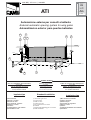
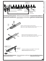
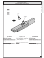
1) Motoriduttore
2) Quadro comando
3) Ricevitore radio
4) Fotocellule di sicurezza
5) Selettore a chiave
6) Antenna
7) Lampeggiatore di movimento
8) Trasmettitore radio
1) Irreversible gear motor
2) Control panel
3) Radio receiver
4) Safety photocells
5) Key-operated selector switch
6) Antenna
7) Flashing light indicating gate movement
8) Radio transmitter
1) Motorreductor irreversible
2) Cuadro de mando
3) Radiorreceptor
4) Fotocélulas de seguridad
5) Selector a llave
6) Antena
7) Lámpara intermitente de movimiento
8) Transmisor
Automazione esterna per cancelli a battente
External automatic opening system for wing gates
Automatizacion exterior para puertas batientes
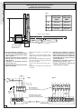
Wiring for microswitches:
5 x 1mm
2
Power wires to motor:
2 x 1,5 mm
2
up to 20 m;
2 x 2,5 mm
2
up to 30 m
Cavi di collegamento microinterruttori:
5 x 1 mm
2
Cavi di alimentazione motore:
2 x 1,5 mm
2
fino a 20 m;
2 x 2,5 mm
2
fino a 30 m.
Cables de conexión microinterruptores:
5 x 1 mm
2
Câbles de alimentación motor:
2 x 1,5 mm
2
hasta 20 m;
2 x 2,5 mm
2
hasta 30 m
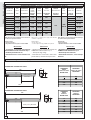
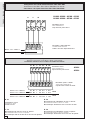
A 3024 - A 5024
Impianto tipo
Standard installation
Instalacion tipo
4 x 1,5
2 x 1 - TX
4 x 1
2 x 1,5
3 x 1,5
2 x 1
3 x 1
230 V
4 x 1 - RX
T RG58
4 x 1,5
8
1
1
5
4
3
4
2
4
4
7
6

-2-
ITALIANO • ENGLISH • ESPAÑOL
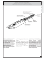
793
300
720
88
126
A3000/A3006-A3100/A3106-A3024
A5000/A5006-A5100/A5106-A5024
88
993
500
920
126
Misure d'ingombro e limiti d'impiego /
Overall dimensions and use limiets
/ Dimensiones máximas y limites de empleo
Caratteristiche tecniche -
Tecnichal caracteristics
-
Características técnicas
Datos relativos a los valores de la tension nominal y a
las condiciones de apertura estándar;
(R) Reversible
* Servicio intensivo;
**Ajustable mediante los cuadros de mando CAME
Data refers to nominal power supply and standard
conditions of aperture;
(R) Reversible;
* Heavy duty cycle;
** Can be adjusted using CAME control panels;
Dati relativi ai valori di alimentazione nominale e a
condizioni di apertura standard;
(R) Reversibile;
* Servizio intensivo;
** Regolabile mediante quadri comando CAME
Corsa |
Travel
| Recorrido
Corsa |
Trave l
Recorrido
LARGHEZZA
ANTA
WIDTH OF WING
ANCHO HOJA
PESO ANTA
WEIGHT OF WING
PESO HOJA
m Kg
2.00 800
2.50 600
3.00 400
LARGHEZZA
ANTA
GEWICHT
ANCHO HOJA
PESO ANTA
GEWICHT
PESO HOJA
m Kg
2.00 1000
2.50 800
3.00 600
4.00 500
5.00 400
EROTTUDIROTOMOSEPENOIZATNEMILA
ETNERROC
ELANIMON
AZNETOP
AZNETTIMRETNI
OROVAL
IDOTROPPAR
ENOIZUDIR
ATNIPSASROCOPMETEROTASNEDNOC
ROTOMRAEGTHGIEWYLPPUSREWOP
LANIMON
TNERRUC
REWOPELCICYTUDOITARNOITCUDERHSUPEMITLEVARTROTICAPAC
ROTCUDERROTOMOSEPNOICATNEMILA
ETNEIRROC
LANIMON
AICNETOP
AICNETIMRETNI
OJABART
EDNOICALER
NOICCUDER
EJUPME
EDOPMEIT
ODIRROCER
RODASNEDNOC
0003A
gK01 .c.aV032 A2,1 W051 %05
63/1
÷004**
N0003
s91
Fµ01
6003A s82
4203A gK5,8 .c.aV42 A01 W021 * s81** -
)R(0013A
gK5,9 .c.aV032 A2,1 W051 %05
s91
Fµ01
)R(6013A s82
0005A
gK11 .c.aV032 A2,1 W051 %05
s23
Fµ01
6005A s54
4205A gK5,9 .c.aV42 A01 W021 * s03** -
)R(0015A
gK5,01 .c.aV032 A2,1 W051 %05
s23
Fµ01
)R(6015A s54
DESCRIPTION:
- Designed and constructed entirely by
CAME Cancelli Automatici S.p.a
- IP54 protecting rating;
- Guaranteed for 24 months, unless tam-
pered with by unauthorized personnel.
DESCRIPCIÓN:
- Diseñado y fabricado enteramente por
CAME Cancelli Automatici S.p.a
- Grado de protección IP54;
- Garantizado 24 meses, salvo manipu-
laciones.
DESCRIZIONE:
- Progettato e costruito interamente
dalla CAME Cancelli Automatici S.p.a.
- Grado di protezione IP 54;
- Garantito 24 mesi salvo manomissio-
ni.

-3-
ITALIANO • ENGLISH • ESPAÑOL
C
Prima di procedere all’installazione
dell’automatismo, controllare:
- che la struttura del cancello sia ade-
guatamente robusta, le cerniere sia-
no efficienti e che non vi sia attrito tra
parti fisse e mobili;
- che la misura C non sia superiore al
valore indicato nella Tab. 3, pag. 4. In
tal caso è necessario intervenire sul
pilastro in modo da raggiungere tale
misura;
- il percorso dei cavi elettrici secondo
le disposizioni di comando e sicurez-
za;
- che ci sia una battuta d'arresto mec-
canico in chiusura (ben fissata al suo-
lo) per evitare l'oltrecorsa anta/
motoriduttore.
Before beginning installation of the automa-
tion system, check the following:
- the structure of the gate must be sufficiently
strong; the hinges must function efficiently
and there must be no friction between the
moving parts and fixed parts;
- measurement C must not be greater than
the value shown in Tab. 3 (page 4). If this is
the case, it is necessary to modify the pillar
so that this measurement cor-responds;
- the electrical wiring path according to the
position of the control and safety instru-
ments;
- presence of a mechanical gate stop (secu-
rely anchored to the ground) in the closed
position in order to prevent the gate and the
reduction gear from moving beyond the
correct close position.
Antes de proceder a la instalación del
automatismo, controlar:
- la estructura de la puerta sea lo sufi-
cientemente sólida, las bisagras sean
eficientes y que no haya rozamiento
entre las piezas fijas y aquéllas móvi-
les;
- la medida C no sea superior al dato
indicado en la Tab.3, pág. 4. En tal
caso, es necesario actuar sobre el pilar
hasta alcanzar dicha medida;
- el recorrido de los cables eléctricos
según las disposiciones de mando y
seguridad;
- la existencia de un tope para el cierre
(bien fijado en el suelo) para evitar que
la hoja/motorreductor llegue más allá
de lo requerido.
Controlli generali -
General control procedure -
Controles generales
Pilastro
Pillar
Pilar
Cerniera
Hinge
Bisagra
Anta
Leaf
Hoja
Battuta d’arresto
Gate stopper
Tope

-4-
ITALIANO • ENGLISH • ESPAÑOL
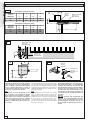
A3000/A3006 -A3100/A3106 -A3024
A5000/A5006 -A5100/A5106 -A5024
Tab. 3
1a
1
M8x38
M8
1b
A
C
B
E
B
A
Applicare al pilastro la piastra di fissaggio
con la staffa di coda (fig. 1) rispettando le
quote A e B (Tab. 3) tra l'asse della cerniera
e il foro centrale della staffa. La staffa di
coda è dotata di ulteriori forature per varia-
re l'angolo di apertura del cancello.
N.B.:
aumentando la misura B diminuisce l'an-
golo di apertura con conseguente diminu-
zione della velocità periferica e aumento
della spinta motore sull'anta. Aumentando
la misura A aumenta l'angolo di apertura
con conseguente aumento della velocità
periferica e diminuzione della spinta moto-
re sull'anta.
Attach the fixing plate and the rear bracket (fig.
1) to the pilar observing measurement A and B
shown in Tab. 3, between the hinge pin and the
central hole in the bracket. The rear bracket is
equipped with additional holes to change the open-
ing angle of the gate.
N.B.:
if measurement B is increased, the opening
angle is reduced. This therefore reduces the
peripheral speed and increases the thrust ex-
erted by the motor on the gate. If measurement
A is increased, the angle of aperture is in-
creased. This therefore increases the periph-
eral speed and reduces the thrust exerted by
the motor on the gate.
Den hinteren Bügel mit der entsprechen-
den Klemmplatte (Abb. 1) unter Einhaltug
der Maße A und B (Tab. 3), und zwar dem
Achsenabstand zwischen zentraler Bügel-
bohrung und Torangelzapfen, am Torpfei-
ler befestigen. Der hinteren Bügel ist mit
einer Reihe von Bohrungen versehen, um
eine Änderung des Toröffnungswinkels zu
erlauben.
Wichtig!
Beachten Sie bitte, daß bei Erhöhen des
Maßen B der Toröffnungswinkel und dem-
zufolge auch die periphärische Torlauf-
geschwindigkeit vergrößert und der auf
den Torflügel ausgeübte Motorschub re-
duziert.
Montaggio -
Assembly
- Montaje
Pilastro
Pillar
Pilar
Cerniera
Hinge
Bisagra
Anta pos. chiusura
Wing closed
Hoja cerrrada
Piastra di fissaggio
Fixing plate
Placa de fijación
Staffa di coda
Rear bracket
Soporte trasero
Boccola
Bushing
Casquillo
Snodo di coda
Rear joint
Articulacìon
trasera
APERTURA
OPENING
ABERTURA
A
mm
B
mm
C max
mm
E
mm
90° 130 130 60 720
120° 130 110 50 720
APERTURA
OPENING
ABERTURA
A
mm
B
mm
C max
mm
E
mm
90° 200 200 120 920
130° 200 140 70 920

-5-
ITALIANO • ENGLISH • ESPAÑOL
E
M8x10
M8x50
A cancello chiuso applicare sull'anta la
piastra di fissaggio, accertandosi che la
staffa di testa sia in asse orizzontale con
la staffa di coda e rispettando la misura
E.
With the gate closed, attach the fixing plate
with the front bracket to the gate wing. The
anchor plate must be horizontally aligned
with the rear bracket and measurement E
must be observed.
Con la puerta cerrada, incorporar a la
hoja la placa de fijación mediante el so-
porte delantero, en línea horizontal con el
soporte trasero, respetando la medida
E.
Svitare le due viti di fissaggio del carter ed estrarlo.
Remove thje two screws which hold the casing in position and remove the rod.
Aflojar los dos tornillos de fijación del cárter y sacarlo.
Svitare le due viti di fissaggio dello stelo ed estrarlo.
Remove thje two screws which hold the rod in position and remove the rod.
Aflojar los dos tornillos de fijación del vástago y sacarlo.
N.B: è consigliabile lubrificare (con gras-
so neutro) la vite senza fine e la boccola
al momento dell'installazione.
N.B: use neutral grease to lubricate the
wormgear and the washer at the moment
of installation.
Nota: es aconsejable lubricar (con grasa
neutra) el tornillo sin fin y la arandela en
el momento de la instalación.
Procedere al montaggio del motoriduttore alle due staffe.
Install the gear motor on the two brackets
Montar el motorreductor en los dos soportes.
Piastra di fissaggio
Fixing plate
Placa de Fijación
Livellare la staffa
Level the braket
Nivelar el soporte
Staffa di testa
Front bracket
Soporte delantero
Carter
Casing
Cárter
Dado M8 autobloccante
M8 locknut
Tuerca M8 de seguridad
Vite senza fine
Worm-gear
Tornillo sin fin
Stelo
Rod
Vástago

-6-
ITALIANO • ENGLISH • ESPAÑOL
A3024
A5024
U V W
N M F FA RC R RA
Collegamenti alle schede elettroniche ZA3 / ZA4 / ZA5 / ZM2
Connections to the ZA3 - ZA4 - ZA5 or ZM2 electronic boards
Conexiones a la tarjeta electrónica ZA3 / ZA4 / ZA5 ó ZM2
A3000 - A3006 - A3100 - A3106
A5000 - A5006 - A5100 - A5106
Morsettiera motore
Motor terminal block
Caja de bornes para el motor
Morsettiera scheda elettronica
Terminal board electronics
Tablero de bornes tarjeta electrónica
Motore -
Motor
- Moteur 1 U V W
Motore -
Motor
- Moteur 2 X Y W
Collegamenti elettrici ai quadri comando ZL14 o ZL19
Electrical connections to the ZL14 or ZL19 control panels
Conexiones eléctricas en los cuadros de mando ZL14 ó ZL19
N - M
Collegamento motore
Connection to motor
Conexión motor
F - Fa
Microinterruttore di finecorsa motore in apertura
Microswitch-limit switch of motor on aperture
Microinterruptor final de recorrido motor en la fase de apertura
R - Ra
Microinterruttore di rallentamento motore in apertura
Microswitch-deceleration of motor in aperture
Microinterruptor deceleración motor en la fase de apertura
R - Rc
Microinterruttore di rallentamento motore in chiusura
Microswitch-deceleration of motor on closure
Microinterruptor deceleración motor en la fase de cierre
Morsettiera quadro comando
Control panel terminal block
Caja de bornes cuadro de mando
Morsettiera motore
Motor terminal block
Caja de bornes para el motor
Motore -
Motor
- Moteur 1 N1 M1 C Fa1 Rc1 C Ra1
Motore -
Motor
- Moteur 2 N2 M2 C Fa2 Rc2 C Ra2
Motore -
Motor
- Moteur 1 N1 M1 2 Fa1 Rc1 2 Ra1
Motore -
Motor
- Moteur 2 N2 M2 2 Fa2 Rc2 2 Ra2
ZL14
ZL19

-7-
ITALIANO • ENGLISH • ESPAÑOL
Regolazione microinterruttore STOP in apertura
Adjusting the STOP microswitch for the aperture movement
Regulacion del microinterruptor de STOP en la fase de apertura
Sbloccare il motoriduttore e portare
l'anta in posizione di apertura
massima desiderata. Svitare le viti di
fissaggio del gruppo microinterrutore.
Far scorrere il gruppo
microinterruttore sull'asta porta
microinterruttore fino a raggiungere
l'inserimento dello stesso mediante
contatto sulla slitta azionamento
gruppo microinterruttore.
Fissare il microinterruttore agendo
sulle rispettive viti.
Vite senza fine
Worm-gear
Tornillo sin fin
Madrevite
Screw-nut
Tornillo tuerca
Vite di fissaggio
Fixing screw
Tornillo de fijación
Slitta azionamento microinterruttore
Microswitch actuation runner
Corredera accionamiento microinterruptor
Asta porta-microinterruttore
Support plate microswitch
Chapa porta-microinterruptor
Gruppo microinterrutore
Microswitch unit
Grupo microinterruptor
- Release the gearmotor and move the
door to the maximum desired open
position.
Loosen the fixing screws of the
microswitch unit. Slide the microswitch
unit along the microswitch-support rod
until it is inserted by contact on the
microswitch unit actuation runner.
Fix the microswitch by tightening the
respective screws.
- Desbloquee el motorreductor y
coloque la hoja en la posición de
apertura máxima deseada.
Desenrosque los tornillos de fijación del
grupo microinterruptor. Haga deslizar
el grupo microinterruptor sobre la
varilla porta-microinterruptor hasta que
este se introduzca por contacto sobre
la corredera de accionamiento del
grupo microinterruptor.
Fije el microinterruptor apretando los
tornillos correspondientes.

-8-
ITALIANO • ENGLISH • ESPAÑOL
100 mm
A3024
A5024
IN APERTURA:
Sbloccare il motoriduttore e portare
l'anta in posizione di apertura
massima desiderata, svitare le viti di
fissaggio del gruppo microinterruttori
di rallentamento e di stop in apertura.
Far scorrere il gruppo microinterruttori
sull'asta porta microinterruttore fino a
raggiungere l'inserimento dello stesso
mediante contatto sulla slitta
azionamento microinterruttore.
Fissare il gruppo microinterruttori
agendo sulle rispettive viti.
IN CHIUSURA:
portare l'anta a non oltre 100 mm dalla
battuta d'arresto in chiusura (part. B).
Svitare le viti di fissaggio del gruppo
microinterruttore di rallentamento in
chiusura.
Far scorrere il gruppo microinterruttore
sull'asta portamicrointerruttore fino a
raggiungere l'inserimento dello stesso
mediante contatto sulla slitta
azionamento microinterruttore.
Fissare il gruppo microinterruttore
agendo sulle rispettiva viti.
Regolazione microinterruttori di rallentamento in apertura e in chiusura
Adjusting the deceleration microswitches for aperture and closure
Regulación de los microinterruptores de reducción de la marcha en las fases de apertura y cierre
Battuta d’arresto
Gate jamb
Tope
Viti di fissaggio
Fixing screws
Tornillons de Fijación
Gruppo microinterruttore di
rallentamento e di stop in
apertura
Microswitch unit for slowing
and stopping during opening
Grupo microinterruptor de
deceleración y de parada
en apertura
Madrevite
Screw-nut
Tornillo tuerca
Vite senza fine
Worm-gear
Tornillo sin fin
Microinterruttore di rallentamento in
chiusura
Deceleration microswitch for closure
Micrinterruptor de reduccion de la marcha
en cierre
Asta porta
microinterruttore
Support plate
microswitch
Chapa porta
microinterruptor
Madrevite
screw-nut
Tornilo tuerca
DURING OPENING:
Release the gearmotor and move the
wing to the maximum desired open
position, unscrew the fixing screws of the
deceleration microswitches unit and the
unit that controls the stop during opening.
Slide the microswitches unit along the
microswitch-support rod until it is inserted
by contact on the microswitch unit
actuation runner.
Fix the microswitches unit by tightening
the respective screws.
DURING CLOSURE:
move the wing to no closer than 100 mm
from the end stop during closure (detail
B).
Unscrew the fixing screws of the group
deceleration microswitch during closure.
Slide the microswitch unit along the
microswitch-support rod until it is inserted
by contact on the microswitch unit
actuation runner.
Fix the microswitch unit by tightening the
respective screws.
EN APERTURA:
Desbloquee el motorreductor y coloque
la hoja en la posición de apertura
máxima deseada, desenrosque los
tornillos de fijación del grupo
microinterruptores de deceleración y
de parada en apertura.
Haga deslizar el grupo microinterruptor
sobre la varilla porta-microinterruptor
hasta que este se introduzca por
contacto sobre la corredera de
accionamiento del microinterruptor.
Fije el microinterruptor apretando los
tornillos correspondientes.
EN CIERRE:
Coloque la hoja a no más de 100 mm
del tope de parada de cierre (det. B).
Desenrosque los tornillos de fijación del
grupo microinterruptores de
deceleración en cierre.
Haga deslizar el grupo microinterruptor
sobre la varilla porta-microinterruptor
hasta que este se introduzca por
contacto sobre la corredera de
accionamiento del microinterruptor.
Fije el grupo microinterruptor apretando
los tornillos correspondientes.
Supporto cavo
Cable holder
Soporte paracables
Slitta azionamento
microinterruttore
Microswitch actuation runner
Corredera accionamiento
microinterruptor

-9-
ITALIANO • ENGLISH • ESPAÑOL
A3000
A3006
A3024
A5000
A5006
A5024
CAME
180
Sblocco a chiave personalizzata
Personalized key release
Desbloqueo mediante llave personalizada
Per sbloccare
l'operazione di sblocco va effettuata a
motore fermo:
1) sollevare lo sportellino;
2) inserire e girare la chiave che istanta-
neamente sblocca l'anta;
3) spingere o tirare l'anta manualmente.
Per bloccare nuovamente l'anta è suffi-
ciente reinserire e girare la chiave
Para desbloquear
esta operación se debe efectuar con el
motor parado:
1) levantar el portillo;
2) introducir y girar la llave que ensegui-
da desbloquea la hoja;
3) empujar o tirar la hoja manualmente.
Para bloquear de nuevo la hoja, es sufi-
ciente volver a introducir y girar la llave.
Releasing the unit
perform this step with the motor stopped:
1) raise the access door;
2) insert and turn the key. The gate will be
released immediately;
3) push or pull the gate manually.
The re-lock the gate, simply insert and turn
the key.
Sportellino
Access door
Portillo
Chiave
Key
Llave

-10-
ITALIANO • ENGLISH • ESPAÑOL
A
B
E
A
3
000
-3006
3100-3106
3024
A5000
-5006
5100-5106
5024
A
130 mm 200 mm
B
130 mm 200 mm
E
720 mm 920 mm
TAB. A
N
1
M
1
FF
A1
R
C1
R
1
R
A1
N
2
M
2
FF
A1
R
C2
R
2
R
A2
NM FF
A
R
C
RR
A
UV
W
XY
W
U
W
V
M
U
V
W
Fig. 1 Fig. 2
- Rilevare le quote A e B (Tab. 4).
- Fissare la staffa di coda integrandola
con una staffa supplementare e appli-
carla al pilastro.
- Aprire il cancello (max 90°), rilevare la
quota E (Tab. 4) e fissare all'anta la
staffa di testa.
- Procedere ai collegamenti elettrici
come da figg. 1 e 2;
- Riposizionare e regolare il micro inter-
ruttore di apertura.
- Measure the lenght of "A" and "B" (see
Tab 4).
- Attach the rear bracket together with a
supplementary bracket and fasten both
to the column.
- Open the gate (maximum 90°) and mea-
sure "E" (see Tab 4), then fasten the front
bracket to the gate.
- Connect the wiring as shown in figs. 1
and 2;
- Reposition and adjust the opening mi-
croswitch.
- Determinar las medidas A y B (Tab. 4).
- Fijar el soporte trasero en el pilar, tras
haberlo integrado por oltro adicional.
- Abrir la puerta (max 90°), determinar
la medida E (Tab. 4) y fijar en la hoja el
soporte delantero.
- Proceder a las conexiones eléctricas
de acuerdo con las figs. 1 y 2;
- Coloque nuevamente y regule el mi-
crointerruptor de apertura.
Applicazione per aperture verso l'esterno
Application for outside aperture
Aplicación para apertura hacia exterior
Motore -
Motor
- Moteur 1
Motore -
Motor
- Moteur 2
Morsettiera motore
Motor terminal block
Caja de bornes para el motor
Morsettiera quadro comando
Control panel terminal block
Caja de bornes cuadro de mando
Massa
Ground
Tierra
Esterno
- Outside-
Exterior
Interno -
Insoide
- Interior
Staffa supplementare
Supplementary bracket
Soporte adicional

-11-
ITALIANO • ENGLISH • ESPAÑOL
MANUTENZIONE PERIODICA /
PERIODIC MAINTENANCE
/ MANTENIMIENTO PERIÓDICO
- Lubrificare la vite senza fine e i perni di
rotazione;
- Controllare le viti di fissaggio;
- Verificare l'integrita' dei cavi di collegamen-
to.
- Lubricate the worm screw and the rotating
pins;
- Ceck the clamps screws;
- Ceck the connection cable's soundness.
- Lubrique el tornillo sin fin y los pernos de
rotación;
- Controle los tornillos de sujeción;
- Controle el estado de los cables de co-
nexión.

CANCELLI AUTOMATICI
CAME LOMBARDIA S.R.L.______COLOGNO M. (MI)
(+39) 02 26708293 (+39) 02 25490288
CAME SUD S.R.L. ___________________NAPOLI
(+39) 081 7524455 (+39) 081 7529109
CAME (AMERICA) L.L.C.____________MIAMI ( FL)
(+1) 305 5930227 (+1) 305 5939823
CAME AUTOMATISMOS S.A__________MADRID
(+34) 091 5285009 (+34) 091 4685442
CAME BELGIUM NU - SA LESSINES
(+32) 068 333014 (+32) 068 338019
CAME FRANCE S.A.____NANTERRE CEDEX ( PARIS)
(+33) 01 46130505 (+33) 01 46130500
CAME GMBH________KORNTAL BEI (STUTTGART)
(+49) 07 11839590 (+49) 07 118395925
CAME GMBH____________SEEFELD BEI ( BERLIN)
(+49) 03 33988390 (+49) 03 339885508
CAME PL SP.ZO.O______________WARSZAWA
(+48) 022 8365076 (+48) 022 8369920
CAME UNITED KINGDOM LTD___NOTTINGHAM
(+44) 01159 210430 (+44) 01159 210431
CAME CANCELLI AUTOMATICI S.P.A.
DOSSON DI CASIER (TREVISO)
(+39) 0422 4940 (+39) 0422 4941
SISTEMA QUALITÀ
CERTIFICATO
ASSISTENZA TECNICA
NUMERO VERDE
800 295830
W
EB
www.came.it
E-MAIL
Tutti i dati sono stati controllati con la massima cura. Non ci
assumiamo comunque alcuna responsabilità per eventuali errori
od omissioni.
All data checked with the maximum care. However, no liability is
accepted for any error or omission.
Todos los datos se han controlado con la máxima atención. No
obstante no nos responsabilizamos de los posibles errores u
omisiones.
DICHIARAZIONE DEL FABBRICANTE
Ai sensi dell’Allegato II B della Direttiva Macchine 98/37/CE
I Rappresentanti della
CAME Cancelli Automatici S.p.A.
via Martiri della Libertà, 15
31030Dosson di Casier - Treviso - ITALYtel
(+39) 0422 4940 - fax (+39) 0422 4941
internet: www.came.it - e-mail: [email protected]
Dichiarano sotto la propria responsabilità che i/il prodotto/i denominato/i ...
… sono conformi alle disposizioni legislative Nazionali che traspongono le seguenti Direttive
Comunitarie (dove specificatamente applicabili):
DIRETTIVA MACCHINE 98/37/CE
DIRETTIVA BASSA TENSIONE 73/23/CEE - 93/68/CEE
DIRETTIVA COMPATIBILITÀ ELETTROMAGNETICA 89/336/CEE - 92/31/CEE
DIRETTIVA R&TTE 1999/5/CE
Inoltre, dichiara che il/i prodotto/i, oggetto della presente dichiarazione, sono costruiti nel rispetto
delle seguenti principali norme armonizzate:
EN 292 PA R T E 1ª E 2ª SICUREZZA DEL MACCHINARIO.
EN 12453 CHIUSURE INDUSTRIALI, COMMERCIALI …
EN 12445 CHIUSURE INDUSTRIALI, COMMERCIALI …
EN 60335 - 1 SICUREZZA NEGLI APPARECCHI AD USO DOMESTICO ...
EN 60204 - 1 SICUREZZA DEL MACCHINARIO.
EN 50081 - 1 E 2COMPATIBILITÀ ELETTROMAGNETICA.
EN 50082 - 1 E 2COMPATIBILITÀ ELETTROMAGNETICA.
AVVERTENZA IMPORTANTE!
È vietato mettere in servizio il/i prodotto/i, oggetto della presente dichiarazione, prima del
completamento e/o incorporamento, in totale conformità alle disposizioni della Direttiva
Macchine 98/37/CE
Firma dei Rappresentanti
Documentazioni tecniche specifiche dei prodotti sono disponibili a richiesta!
Data della presente dichiarazione 07/12/2001
A3000 • A3006 • A3100 • A3106 • A3024 • A3124
A5000 • A5006 • A5100 • A5106 • A5024 • A5124
D001 • H3000 • LOCK81 • LOCK82
Also, they furthermore represent and warrant that the product/s that are the subject of the present
Declaration are manufactured in the respect of the following main harmonized provisions:
EN 292 PA RT 1 AND 2MACHINERY SAFETY.
EN 12453 INDUSTRIAL, COMMERCIAL AND OTHER CLOSING MECHANISMS.
EN 12445 INDUSTRIAL, COMMERCIAL AND OTHER CLOSING MECHANISMS.
EN 60335 - 1 SAFETY IN APPARATUSES FOR HOME USE.
EN 60204 - 1 MACHINERY SAFETY.
EN 50081 - 1 AND 2ELECTROMAGNETIC COMPATIBILITY.
EN 50082 - 1 AND 2ELECTROMAGNETIC COMPATIBILITY.
IMPORTANT CAUTION!
It is forbidden to market/use product/s that are the subject of this declaration before completing and/
or incorporating them in total compliance with the provisions of Machinery Directive 98/37/CE
Signatures of the Representatives
Specific technical documentation on the products is available on request!
Date of the present declaration 07/12/2001
MANUFACTURER’S DECLARATION
As per Enclosure II B of Machinery Directive 98/37/CE
The representatives of
CAME Cancelli Automatici S.p.A.
via Martiri della Libertà, 15
31030 Dosson di Casier - Treviso - ITALY
tel (+39) 0422 4940 - fax (+39) 0422 4941
internet: www.came.it - e-mail: [email protected]
Hereby declare, under their own respons ibility, that the product/s called ...
… comply with the Italian National Legal Provisions that transpose the
following Community Directives (where specifically applicable):
MACHINERY DIRECTIVE 98/37/CE
LOW VOLTAGE DIRECTIVE 73/23/EEC - 93/68/EEC
LECTROMAGNETIC COMPATIBILITY DIRECTIVE 89/336/EEC - 92/31/EEC
R&TTE DIRECTIVE 1999/5/CE
DECLARACION DEL FABRICANTE
De conformidad con el Anexo II B de la Directiva de Máquinas 98/37/CE
Fecha de la presente declaración 07/12/2001Adjunta a la documentación técnica (el original de la Declaración está disponible previa petición)
Los Representantes de la compañía
CAME Cancelli Automatici S.p.A.
via Martiri della Libertà, 15
31030 Dosson di Casier - Treviso - ITALY
tel (+39) 0422 4940 - fax (+39) 0422 4941
internet: www.came.it - e-mail: [email protected]
Declaran bajo su responsabilidad que el/los producto/s denominado/s ...
… cumplen con las disposiciones legislativas nacionales que trasponen las siguientes
Directivas Comunitarias (donde específicamente aplicables):
DIRECTIVA DE MÁQUINAS 98/37/CE
DIRECTIVA DE BAJA TENSIÓN 73/23/CEE - 93/68/CEE
DIRECTIVA DE COMPATIBILIDAD ELECTROMAGNÉTICA 89/336/CEE - 92/31/CEE
DIRECTIVA R&TTE 1999/5/CE
A3000 • A3006 • A3100 • A3106 • A3024 • A3124
A5000 • A5006 • A5100 • A5106 • A5024 • A5124
D001 • H3000 • LOCK81 • LOCK82
Los productos objeto de esta declaración están fabricados respetando las siguientes normas
armonizadas:
EN 292 PAR TE 1ª Y 2ª SEGURIDAD DE LAS MÁQUINAS.
EN 12453 CIERRES INDUSTRIALES, COMERCIALES …
EN 12445 CIERRES INDUSTRIALES, COMERCIALES …
EN 60335 - 1 SEGURIDAD DE LOS APARATOS PARA USO DOMÉSTICO...
EN 60204 - 1 SEGURIDAD DE LAS MÁQUINAS.
EN 50081 - 1 E 2COMPATIBILIDAD ELECTROMAGNÉTICA.
EN 50082 - 1 E 2COMPATIBILIDAD ELECTROMAGNÉTICA.
AVVERTENZA IMPORTANTE!
Está prohibido hacer uso de el/los producto/s, objeto de la presente declaración antes de completarlo/
s y/o incorporarlo/s en total conformidad a las disposiciones de la Directiva de Máquinas 98/37/CE.
Firma de los Representantes
Documentación técnica específica de los productos está disponible previa petición
Enclosed with the technical documentation (the original copy of the Declaration is available on request)
Allegata alla documentazione tecnica (l’originale della Dichiarazione è disponibile a richiesta)
RESPONSABILE TECNICO
Sig. Gianni Michielan
PRESIDENTE
Sig. Paolo Menuzzo
TECHNICAL MANAGER
Mr. Gianni Michielan
MANAGING DIRECTOR
Mr. Paolo Menuzzo
A3000 • A3006 • A3100 • A3106 • A3024 • A3124
A5000 • A5006 • A5100 • A5106 • A5024 • A5124
D001 • H3000 • LOCK81 • LOCK82
RESPONSABLE TÉCNICO
Sr. Gianni Michielan
PRESIDENTE
Sr. Paolo Menuzzo
-
 1
1
-
 2
2
-
 3
3
-
 4
4
-
 5
5
-
 6
6
-
 7
7
-
 8
8
-
 9
9
-
 10
10
-
 11
11
-
 12
12


CAME ATI Manuale del proprietario
- Categoria
- Gate Opener
- Tipo
- Manuale del proprietario
in altre lingue
- English: CAME ATI Owner's manual
- español: CAME ATI El manual del propietario
Documenti correlati
-
CAME A 3000 Guida d'installazione
-
-
-
-
-
-
-
-
-
CAME BX Series Manuale del proprietario