
MTP41S User Manual
Wideband Wireless
Professional Pocket
Transmitter
SN: ________________
Rev.03 (rif. FW 1.30.0P)
Date: 24 November 2017

MTP41S User Manual
2
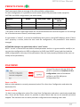
INTRODUCTION
“MTP41S is an extremely small and light pocket transmitter especially designed for professional
wireless microphone applications”
Very easy and quick to use thanks to OLED display, dedicated buttons and a joggle selector.
MTP41S benefits also of the latest Wisycom RF technology along with an enhanced robustness
against noise and inter-modulation.
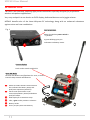
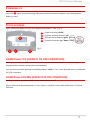
Fig. 1
1.
Fig. 2
❶
Switch to enable wireless transmission it
also indicates the battery status and
peak/mute operation (with PTT)
❷
LED to show information on RF
transmission/battery status/modulation
peek/PTT status
❸
Oled display for transmitter setup
❹
<ch>, <gain> and 3 positions <selector>
❺
Battery holder
❻
Cover (to open push side buttons)
Turn on wireless:
Move the Wireless power switch in
“I” position:
A green blinking gives you
indications on battery status.
1
Open MIC Body:
Push the side buttons and flip down the cover, to access
internal setup controls and batteries.
Turn on display:
Push <select switch> and hold it.
2
3
5
6
4

MTP41S User Manual
3
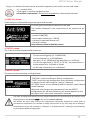
SAFETY INSTRUCTION
Read this safety instruction and the manual first
Follow all instructions and information.
Do not lose this manual.
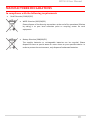
Do not use this apparatus under the rain or near the water.
Do not install the apparatus near heaters or in hot environments, do not use outside the
operating temperature range.
Do not open the apparatus, only qualified service technician are enabled to operate on it. The
apparatus needs servicing when it is not properly working or is damaged by liquids, moisture or
other objects are fallen in the apparatus.
Use only accessories or replacement parts authorized or specified by the manufacturer.
Clean the apparatus only with dry cloths, do not use liquids.
Report the serial number and the purchasing date in front of the manual. It is needed to have
proper replacement parts or accessories from the manufacturer.
When replacement parts are needed, use only replacement parts authorized from the
manufacturer. Substitution with not authorized parts could result in electric shock, hazards or
fire.
Keep attention on all the labels with warnings or hazards on the apparatus.

MTP41S User Manual
4
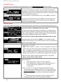
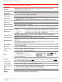
LED INDICATIONS
Led indication with LED RGB (red, green, blue) in front led (❷):
- Wireless transmission status: Green when RF transmission power is on (on power on the
device, this LED is red and become green when the RF transmission power is on).
- Battery status: green steady, slowly blinking (< 25%), quickly blinking (<12%).
- Modulation peek (if activated and the limiter is disabled): red.
- Ptt status: red if active (push to talk “pushed”).
- Limiter in action (if activated): blue.
BATTERIES
MTP41S is working with 1 AA alkaline or NiMH or Lithium batteries (select correct type on setup
controls). Battery status can be checked on internal OLED display or looking the LED status on front
❷.
BATTERY SUBSTITUTION
Open transmitter cover and insert the battery following polarity indicated.
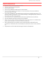
ANTENNAS
MTP41S is supplied with a couple of antennas. According to the working band, different antenna
models can be supplied. All the models have black cap and a black label with code in white colour.
For more details see the below table.
In order to help the user to connect the correct antenna, the
display shows the antenna code during the switch on of the
transmitter and during the tuning selection after a change of
frequency range. (ex. if the user changes the frequency from 566
to 672 MHz, the display shows Ant. 732)
Band
Range
(MHz)
Code
1 470-640 MHz
470-547
507
547-640
590
2 566-798 MHz
566-672
616
672-798
732
3 510-698 MHz
510-595
552
595-698
646
Antenna Code label

MTP41S User Manual
5
A
B
C
D
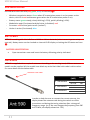
POWERING UP
Move the wireless power switch (see Fig. 1) in “I” position to activate wireless transmission: the
front LED ❷ lights up red and then green when the RF transmission power is on (blinking when
battery is low!)
SETUP CONTROL
Open transmitter Body to access the “display and controls” area (Fig. 3):
A. Graphics Display (OLED)
B. Channel selection buttons (ch)
C. MIC gain setup buttons (gain)
D. 3 position selector (up / down / click)
Fig. 3
OLED Power UP (OLED IS IN OFF CONDITION)
Pushing down selector (click), oled turns on. A first menu with Serial Number and brand logo is
displayed, then <status> menu enters automatically.
Turn on the transmitter pushing and holding selector (click) > 2 sec, Serial Number menu is displayed
till (-/+) is selected.
OLED Power DOWN (OLED IS IN ON CONDITION)
Pushing and holding selector (click) > 2 sec, display is turned off.
Display turns off automatically after 15 sec, unless in <AUDIO> menu (with audio level < 5% from
nominal).
+
-
CLICK

MTP41S User Manual
6
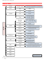
DISPLAY MENU
MENU
STATUS
PRESET
Current / Load
FACTORY/USER/PRESET1/2/3/4/5/6/7/8
Save
USER
TUNING
CH 00-59
GR 00-39
Freq
1: 470.000÷640.000
2: 566.000÷798.000
3: 510.000÷698.000
AUDIO
AF In Gain
AF Level
-60 ÷ +40 dB (1dB step)
-54 ÷ +46 dBu (1dBu step)
Phase 0/180
HP Filt
Flat/60/80/120/170/250/400Hz
Noise R.
ENR-Wisy/ENC-Wisy
Limiter
On/Off
MIC
Mode
2 wires/2wires+bias/3 wires
PTT
Disable/Normal/Muting/No Data
RF/Battery
RF Power
10/50mW *
Battery Alkaline/NiMH/Lithium
LED
Led Light 0÷16
Led Mode
None/ModPeak/PTT
INFO
IRDA
Name
Lock
Preset parameters
* Depending on the Power Profile

MTP41S User Manual
7
+
-
CLICK
Using <+/-> selector all menus can be accessed in sequence, push <click> to enter edit mode:
<+/-> to setup field
<click> again to confirm changes and exit.
exit without confirmation if no button is pressed after a few seconds time out.
<START UP> menu
These menus are displayed during power up for few seconds.
First one gives information of antenna to be used.
The number displayed is the center-band of the antenna to be
used.
The second menu gives indication on product:
- product id (MTP41),
- the firmware release (ex. 1.30.0A),
- the band in extended format and
- the serial number.
Keep selector pushed to hold this menu!
<STATUS> menu
This is the first menu displayed after power up.
Major info are displayed:
- Current channel/group (i.e. CH:00 GR:39)
- Current frequency (i.e. 566.000 MHz)
- Mic gain (i.e. AF: +00dB) and high pass filter (i.e. HP:60 Hz)
- If in the top right there is “RF 50” or “RF 10”, the transmission is
active respectively at 50mW or 10mW
- On left side, the battery bar is displayed
<PRESET> menu
This menu can be entered by scrolling selector
MTP41S can recall configuration presets.
“FACTORY” recalls the Wisycom factory configuration.
“USER” recalls the user configuration (the transmitter configuration
is copied into the USER using the “save to” submenu).
All “USER” menus are not locked by default, thus this is quick way to
unlock features!
When the user changes some parameters from the PRESET
configuration (for less than frequency) an asterisk appears on the
top-right corner until a save command is executed.
The other 8 configuration presets are user programmable thru the infrared and the PC interface (using
the programmer UPK 300/UPK
Mini
or the receiver MRK950/MRK960).
We provide the device with some preset configurations specifically designed for certain types of
microphone or applications (it’s possible to change these presets in any time using the TX manager).
All parameters can be “left unchanged”, “changed” or “changed and lock”, allowing a very flexible way
to pre-program MTP41S configuration.

MTP41S User Manual
8
<TUNING> menu
This menu can be entered by scrolling selector or using quick channel setup buttons (<ch>).
In this menu current channel/group and frequencies can be setup.
The name of the group is shown on the top right of the display.
Sync group is a quick self-settable channel synchronized by receiver
(with SYNC group, on the top right of the display is shown the name
of the synchronized receiver).
Use the selector to change values (<+/->) and <click> to confirm.
Using quick channel setup buttons (<CH>), it is possible to enter
quickly in the tuning menu. Note that the menu has a different
layout (see the side image)
<AUDIO> menu
In the AUDIO menu are shown all the audio parameters (this menu can be entered by pushing <+/->).
The sensitivity of the audio input is settable between “AF Gain”
(measured in dB) or “AF Level” (measured in dBu).
To help proper audio gain setting, an audio bar is supplied (with
maximum peak indicator) indicating the headroom to audio peak
(0 dB , nominal deviation 40KHz). Set the gain, with the maximum
input signal, avoiding the peak on the audio bar.
TRY TO SETUP TO HAVE A MAX PEAK HOLD BAR CLOSE TO -6dB.
Using quick gain setup buttons (<GAIN>), it is possible to enter
quickly in the audio gain menu. Note that the menu has a different
layout (see the side image)
The second <AUDIO> menu allows to set:
- Audio phase: 0° or 180°
Note: Since common "2-wires + bias" microphones invert the
phase, when the MIC mode of the transmitter is set to “2wires+
bias”, the phase is automatically inverted and so the complete
system (MTP4x+MIC) has 0° phase (an asterisk appear on the
display near the phase to indicate that the phase was inverted).
- High Pass Filter: applies different audio HP filter: Flat/ 60Hz/
80Hz/ 120Hz/ 170Hz/ 250Hz/ 400Hz.
The third <AUDIO> menu allows to set:
-Noise reduction:
ENR: designed for maximum noise reduction
ENC: designed for maximum audio fidelity (use this in
case of special vocal application or to remote
instruments)
-Limiter: if is set “On”, an input audio signal above the peak
threshold (up to 30 dB above peak) is not cut but attenuate,
without lost quality. The limiter acts as a variable attenuator
(thanks to the feedback system), maintaining a distortion
<3%.
When the limiter intervene, the front led turns blue.
If this parameter is set “Off”, the limiter is disable.

MTP41S User Manual
9
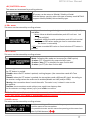
<RF/BATTERY> menu
This menu can be entered by scrolling selector.
RF power can be setup to 100mW, 50mW or 10mW.
Use the Battery menu to select the type of battery used. MTP41S
support Alkaline/NiMH/Lithium battery type.
<LED> menu
This menu can be entered by scrolling selector.
Led Light allows to change the brightness of the front led (0÷16) .
Led Mode:
- None: allows to disable modulation peak LED on front led
(the red light)
- ModPeak: allows to enable modulation peak LED on front led
(become RED when audio get close to saturation when
the limiter is not enable)
- PTT: allows to enable RED color on front led when PTT button is
pushed.
<MIC> menu
This menu can be entered by scrolling selector.
Mode: Following Mic mode can be setup (for LEMO option)
-2 wires: (PTT is possible) for external audio input
-2 wires + bias: (PTT is possible) for most 2 wires MIC
-3 wires: (no PTT) for most 3 wires MIC
PTT setting defines how and what information the transmitter has to send in normal use or when
the PTT button is pushed:
- Disable: when the PTT button is pushed, nothing happen. (the transmitter sends AF+Tone
squelch)
- Normal: when the PTT button is pushed, the transmitter send a different RF signal. According to
the receiver configuration the audio can be enabled/disable on LINE (and/or COM).
- Muting: the transmitter doesn’t send the audio. The voice is cut, it doesn’t enter to the
microphone
- No Data: the transmitter sends neither tone squelch nor battery data.
Use the selector to change values (<+/->) and <click> to confirm.
NOTE: For DPA option (2 pin microdot audio connector), even if the MIC mode menu allows to set one
of the 5 MIC modes, only 2 wires or 2 wires+bias mode are possible.
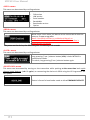
<NAME> menu
This menu can be entered by scrolling selector.
In this menu it’s possible to see the frequency set on the device
and the name of the transmitter.
It’s possible to enter on this menu also pressing at the same time
the CH/GAIN buttons ( B + C )

MTP41S User Manual
10
<INFO> menu
This menu can be entered by scrolling selector.
In this menu it’s possible to see:
- FW version
- HW version
- Serial number
- Bandwidth
- Bootloader version
- Option
<IRDA> menu
This menu can be entered by scrolling selector.
While there is this menu, the device can be connected to IRDA for
setup or firmware upgrades.
Note: if the IRDA interface is enabled and there’s no
communication for around 10 seconds, the IRDA interface is
automatically turned off.
On power on the device, the IRDA interface is enabled for 14 seconds.
<LOCK> menu
This menu can be entered by scrolling selector.
Long pressing (2 sec.) selector button (click) it locks MTP41S in
transmission mode.
To unlock, long pressing (2 sec.) selector button again.
<BOOTLOAD> menu
This menu can be entered by turning on the transmitter while pushing at the same time both quick
channel setup buttons (<ch> & <gain>) or connecting the device via IRDA using the IR Programmer for
FW update
Device is forced in bootloader mode to allow FIRMWARE UPDATE.

MTP41S User Manual
11
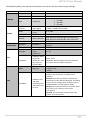
The following table sums up which parameters can be set and the related range settings.
MENU
PARAMETER
MEANING
RANGE SETTINGS
TUNING
CH
Channel
0 ÷ 59
GR
Group
0 ÷ 39 + SYNC GROUP
Freq
Frequency
depends on the MTP41S Model:
1 470-640
2 566-798
3 510-698
AUDIO
AF In Gain
AF Level
Gain of the
audio signal
-60dB ÷ +40dB step of 1dB
-54dBu ÷ +46dBu step of 1dBu
Phase
Audio signal
phase
0° or 180°
HP Filt.
High Pass filter
Flat/60/80/120/170/250/400 Hz
Noise R.
Noise reduction
ENR: Wisycom Extended-NR, noise optimized
ENC: Wisycom Extended-NC, voice optimized
Limiter
Limiter
On/Off
RF/BATTERY
RF Power
RF Power
50mW / 10mW (depending on the power
profile)
Battery
Battery type
Alkaline / NiMH / Lithium
LED
Led Light
Power switch
green
brightness
0 ÷ 16
Led Mode
It defines when
the power
switch led (see
Fig. 3) has to
become RED
None: never
ModPeak: when audio get close to saturation
PTT: when the PTT button is pushed
MIC
Mode
MIC type
’2 wires’
‘2 wires + bias’
‘3 wires’
PTT Mode
It defines how
and what
information the
transmitter has
to send
Disable: when the PTT button is pushed, nothing
happen. (the transmitter sends AF+Tone
squelch).
Normal: when the PTT button is pushed, the
transmitter send a different RF signal. According
to the receiver configuration the audio can be
enabled/disable on LINE (and/or COM).
Muting: the transmitter doesn’t send the audio.
The voice is cut, it doesn’t enter to the
microphone.
No Data: the transmitter sends neither tone
squelch nor battery data.

MTP41S User Manual
12
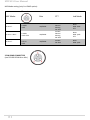
MIC Mode setting (only for LEMO option):
MIC Mode:
Pin out
Gain
PTT
Led Mode
’2 wires’:
1=GND
3=AF
-60/40 dB
Disable
Normal
Muting
No data
None
Mod. Peak
PTT
‘2 wires + bias’:
1=GND
3=AF+5.5V
-60/40 dB
Disable
Normal
Muting
No data
None
Mod. peak
PTT
‘3 wires’:
1=GND
2=5.5V
3=AF
-60/40 dB
Disable
No data
None
Mod. peak
3 PIN LEMO CONNECTOR
(use FVB.00.003.NLN on Mic)

MTP41S User Manual
13
HOW TO USE WISYCOM TX MANAGER
Wisycom TX Manager allows to read, modify and update the configuration of Wisycom transmitters.
It is necessary to
connected the programmer UPK300E/UPKMini or the receiver MRK950/MRK960 to the
PC thru USB connection
run the Wisycom TX Manager
enable the IRDA communication on the transmitter (see IRDA menu)
NOTE: Wisycom IR Programmer doesn’t work whit MRK950/MRK960 if it is connected to the PC
using an Ethernet cable.
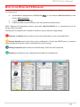
The Wisycom IR Programmer’s window is divided in 4 parts (see the image below):
❶Interface and Device panel contains all the major information of the connected device
❷Current Settings panel shows the current configuration. Thanks the PRESET panel, a previous
saved configuration can be chosen and loaded like current setting.
❸Tuning Frequencies panel allows to handle Groups, Channels and Frequencies
❹Presets panel allows to read, change and save different configurations
❶
❷
❸
❹

MTP41S User Manual
14
10 different configurations are available:
• FACTORY configuration is a locked configuration: no parameter can be changed.
USER configuration is the only configuration that can be saved using the OLED display (see
<PRESET> menu). Note: It is not possible to change the name of this configuration.
Other 8 configurations where the user can change both the name and the values of all
parameters.
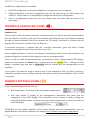
INTERFACE AND DEVICE PANEL (❶)
At the beginning, the program checks which IR devices are detected and they appears on the
Interface panel.
The user has to select the device and push <connect> button in order to open the communication
with the IR device. A picture on the top in the Interface panel help the user in this selection showing
the type of devices detected. During this process the “IR activity” led blinks to indicate that the
program wait connection’s answer from the IR device.
A successful connection is signaled with the “interface connection” green led, while a failed
connection is signaled with the “communication error” led.
Once a supported device is found, the software automatically reads all the data related to the
remote configuration, as well as the frequencies that are pre-programmed.
Firstly, in order to avoid unwanted operation, no parameters can be changes and the EDIT button,
presents on the bottom of Device panel, is yellow and set to LOCKED state. Pushing the EDIT
button, it becomes grey and sets to UNLOCKED state to indicate that the configurations can be
modified.
In this panel it’s possible to assign a name to the TX (not available for FW v.1.22.0F or previous).
Under this parameter, there is a flag to hide the info menu on the TX (not available for FW v.1.22.0F
or previous)
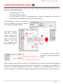
CURRENT SETTINGS PANEL (❷)
In the Current Settings panel the user can
with Preset panel → load one of the 10 available configurations
with other panels → modify all the configuration’s parameters (the same that are
changeable in the OLED display). Each parameter can be locked or hidden clicking the
related lock/hidden button, so the set value cannot be changed next or cannot be visible on
the OLED display.
ATTENTION: All the modifies applied to the Current Settings panel are instantaneous: they are
applied directly to the device and save in its memory but no saved in the preset configuration.

MTP41S User Manual
15
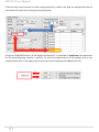
TUNING FREQUENCIES PANEL (❸)
With the Tuning Frequencies panel the user can select a frequencies group (0÷39) and for each one
execute the following operations:
- modify the Group’s Name
- lock and/or hidden the group
- for each channel (0 ÷59) of the selected group: change the frequency value and the
related status (locked/hidden) (in the center grid frequency)
The SAVE button, at the top of the panel,
save the changes of the group selected
(name group, lock/hidden group).
To change a frequency
value for a specific
channel: double click
on the grid frequency
panel (row=channel’s
number), insert the
new frequency value
and press OK button.
To lock/hide a specific channel,
double click on the grid frequency
panel.
NOTE: keeping pressed the CTRL button on the keyboard and clicking the wanted channel/group
shown on the frequencies grid, the tuning process is executed. It is equivalent to configure the
Tuning in the Current Settings panel but it is easier. The device is re-tuned immediately, so be sure
that the RF power is turned off while changing frequencies with other RF systems in use around you!

MTP41S User Manual
16
If the currently tuned channel is on the same group that is listed on the grid, the background color of
the related cell (channel) on the grid becomes yellow.
Using the LOAD/SAVE button, at the bottom of the panel, it is possible to load/save the frequencies
for the selected group from/to a .wdf file. To save the frequencies of all the groups click to the
related button above. The legacy option save the channels without the hidden/lock info.

MTP41S User Manual
17
PRESETS PANEL (❹)
The Preset panel allows to manage all the 10s available configurations.
For each configuration it is possible to set the name and all the parameters value except for
FACTORY and USER configurations (see table below).
PRESETS:
NAME*
LOCK/DON’T CARE
PARAMETERS
VALUE
FACTORY
USER
√
OTHERS
√
√
√
√=change is allowed
* Be careful to write a meaningful name for the preset because the name will appear on the settings
list of the device menu! Please, avoid empty names.
If a parameter is “locked”, it cannot be modified by device menu (using OLED display), while if “don’t
care” propriety is active, when the user load the configuration, the parameter’s value doesn’t
changed.
ATTENTION: Changes are applied only after a “save” action.
NOTE: “a trick” In case of the user have a locked parameter and he is in great need for modify it, he
can save the configuration to USER configuration by OLED (see PRESET menu) and then load the
USER configuration (in this way all the parameters have the lock propriety disable and the user can
modify all the parameters).
FILE MENU
Using a file menu at the top left of the
panel it is possible to load/save all the
configuration values of the device
to/from a .wcf file (Wisycom
Configuration File).
Save a .wcf file
With an infrared device correctly connected, select File->Save User Configuration and select the
destination file.
Load a .wcf file
To load a user configuration select File->Load User Configuration and select a previously saved data
file; a form will be shown, where it's possible to select which data has to be restored and which
skipped. This allow the user to load a particular configuration while keeping other data.

MTP41S User Manual
18
TECHNICAL SPECIFICATIONS
Switchable
channels
2400 allocated by 40 groups of 60 channels (in specific frequency range), quickly
selectable with dedicated buttons
Switching window
Up to 232 MHz, depending on band (see Variants on the next page)
Frequencies
Quartz PLL frequency synthesizer circuit (25 kHz step)
Frequency stability
▪ ± 2,5 ppm (in the rated temperature range)
Temp.range
-10 ÷ +55 °C
Max RF power
▪ 10mW (ERP) (to respect some local norm)
▪ 50mW (ERP) (note: in some countries middle power can be disabled, for local norm!)
Spurious emissions
< 2 nW
Modulation
wideband FM with pre-emphasis
Nominal deviation
±40 kHz (Peak deviation = ±56 kHz)
Telemetry feature
MTP41S transmits also a digitally modulated sub-carrier, suitable for:
▪tone-squelch operating
▪ remote battery monitoring
▪ optional PTT (push to talk) operation
AF input connector
LEMO option
Configurable on ‘mic’ display menu in 3 options:
▪ ’2 wires’:
▪ ‘2 wires + bias’:
▪ ‘3 wires:
gain selectable -60 ÷ +40 dB (-54 dBu ÷ +46 dBu peak), no bias voltage
gain selectable -60 ÷ +40 dB (-54 dBu ÷ +46 dBu peak), 5.5 V on 4k7 bias supply
gain selectable -60 ÷ +40 dB (-54 dBu ÷ +46 dBu peak)
AF input level
100 dB adjustable range from -54 dBu (775 uV) to 46 dBu (15.5 V) at peak deviation
(1 kHz), adjustable in 1 dB steps
Max. input level
+46 dBu (15.5 V) at clipping, +20 dBu (7.75 V) at nominal level
Noise-Reduction
ENR (Wisycom Extended-NR), with independent Attack- and Recovery-time, noise
optimized
ENC (Wisycom Extended-NC), with independent Attack- and Recovery-time, voice
optimized & with reduced pre-emphasis
AF bandwidth
▪ 45 Hz ÷ 21 KHz (3dB)
▪ 55 Hz ÷ 20 KHz (1dB)
Distortion
< 0.3 % (0.15 % typ.)
Signal-to-noise
ratio
▪ typ. 115 dB (A)
rms
with 40 kHz deviation
▪ typ. 121 dB (A)
rms
with 56 kHz deviation
Led
Led indication with bicolor led (red & green) on wireless power switch:
▪ Wireless transmission status:
GREEN on/off
▪ Battery lifetime status: GREEN - steady (> 25%)
- slowly blinking (< 25%) - quickly blinking (<12%)
▪ Modulation peek (if activated & the
limiter is disabled): RED
▪ Ptt status: RED if active
▪ Limiter into action: Blue
Display
High contrast OLED (Organic light-emitting diode) bicolor display (96 x 36 pixels)
8 step battery lifetime indication: 7 bars (100%-87%-75%-63-50%-38%-25%) and “empty
bar” quickly blinking (12% remaining)
PTT function
Pin 3 of the AF connector can be setup to an external push button
Power supply
1 AA size batteries (Alkaline, rechargeable NiMH, Lithium)
MTP41S Battery
life
▪ approx. 11 hours @ 50mW continuous working Lithium
▪ approx. 8 hours @ 50mW continuous working with NiMH
▪ approx. 4.5 hours @ 50mW continuous working with Alkaline
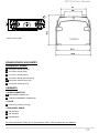
Dimensions
58.2 x 64.5 x 21.7 mm (Height-Width-Depth)
Weight
Approx. 80 g. without batteries (120g with batt.)

MTP41S User Manual
19
VARIANTS:
▪ AUDIO CONNECTOR
LM 3 PIN LEMO CONNECTOR
DP 2 PIN DPA MICRODOT CONNECTOR
▪ COLOR
BL color black (powder coating)
▪ FREQUENCY RANGE
B5 470-654 MHz
B2 566-798 MHz
B3 510-698 MHz
For the commercial code, see in the Variants area of the Products on our website
POWER PROFILE & COUNTRY
FREQUENCY RANGE:
EU max power 50mW (Europe)
US max power 50mW (USA)
JP max power 10mW (Japan)
NZ max power 50mW (New Zealand)
AU max power 50mW (Australia)
CN max power 50mW (China)
Note: unit is mm
MTP41S

MTP41S User Manual
20
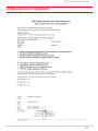
Compliance
Model
In Compliance with
Max Power
Country
MTP41S-EU
EN 301 489-1/-9
EN 600065
EN 300 422-1/-2
50mW
Europe
MTP41S-JP
202-LSD045
Limited to 714 MHz
10mW
Japan
MTP41S-NZ
EN 300 422-1/-2
EN 300 454-1/-2
Limited to the range
502÷698MHz
50mW
New Zealand
MTP41S-AU
Limited to the range
520÷694MHz
50mW
Australia
Before putting the device into operation, please
observe the respective country-specific regulations!
R
MIC marking identifier can be found in the battery compartment.
La pagina si sta caricando...
La pagina si sta caricando...
La pagina si sta caricando...
La pagina si sta caricando...
-
 1
1
-
 2
2
-
 3
3
-
 4
4
-
 5
5
-
 6
6
-
 7
7
-
 8
8
-
 9
9
-
 10
10
-
 11
11
-
 12
12
-
 13
13
-
 14
14
-
 15
15
-
 16
16
-
 17
17
-
 18
18
-
 19
19
-
 20
20
-
 21
21
-
 22
22
-
 23
23
-
 24
24


