
Multi-band
Quad True Diversity
Camera Receiver
rev.6 (reference FW 1.3)
Date: 16 September 2020
MCR54 User Manual

MCR54 User Manual
1
SAFETY INSTRUCTION
Read this safety instruction and the manual first
Follow all instructions and information.
Do not lose this manual.
Do not use this apparatus under the rain or near the water.
Do not install the apparatus near heaters or in hot environments, do not use outside the
operating temperature range.
Do not open the apparatus, only qualified service technicians are authorized to operate on it.
The apparatus needs servicing when it is not properly working or is damaged by liquids,
moisture or other objects are fallen in the apparatus.
Use only accessories or replacement parts authorized or specified by the manufacturer.
Clean the apparatus only with dry cloths, do not use liquids.
Report the serial number and the purchasing date in front of the manual. It is needed to have
proper replacement parts or accessories from the manufacturer.
When replacement parts are needed, use only replacement parts authorized from the
manufacturer. Substitution with not authorized parts could result in electric shock, hazards or
fire.
Keep attention on all the labels with warnings or hazards on the apparatus.
WARNING: The apparatus is intended for professional use; the manufacturer alerts the user that
the headphone output power of the apparatus could exceed the level of 85 dB(A) of sound
pressure level and this could be dangerous for the hearings. Do not use the headphone with high
power level or for long time. Reduce the power or suspend the hearing in case of any kind of
hearing problem.

MCR54 User Manual
2
MAIN FEATURES
MCR54 is a camera mount quad true diversity wireless-microphone receiver system in a modular
stand-alone or slot-in configuration (compatible with most camera’s slot):
Wideband just isn’t enough anymore! Upgrade to a Multi-Band system with up 790 MHz
tuning range to find your frequency, anywhere in the World.
With the combination of Narrowband Modulation (High Density) and Linear transmitters,
set your channels every 200kHz without intermodulation distortion and get an extra 3dB
sensitivity.
With eight internal receiver boards, the MCR54 boasts an unprecedented capacity for
range and reliability.
DSP delivers ENC and ENR algorithms for perfect audio in any application with less than
1ms delay –Create and shape presets for the desired sound. This enables the use of
third-party transmitters with Wisycom receivers
Modular configurations for stand-alone or slot-in formats in many Cameras or Audio
Devices
Monitor & control through USB C or Bluetooth 5 (long range) on Wisycom Manager 2.2
(computer SW)
High contrast OLED display and 4 buttons enable quick manual setup
DSP Analog & Digital Audio Output (AES3)
Extreme low noise VCO with ultrafast spectrum scan for optimal quick & easy setup
Wisycom exclusive digital sub-carrier telemetry technology enables:
o
remote TX battery monitoring
o
advanced tone-squelch operating
o
Push-to-talk function (via optional back-panel module):
Simply pushing this button (PTT), the presenter causes the remote switching of the
receiver’s output-line, from the “main line” to the additional “intercom line”, in order to
be able to talk “off-air” directly with the technical team. Then all PTT’s MICs can be
connected in pre-fading allowing a clever intercom setup.
Rear antenna connectors and micro audio and power adapter
40 groups of 60 channels fully user programmable (2400 frequencies)
TECHNICAL DESCRIPTION
The MCR54 is a professional quad true diversity receiver for wireless microphones reception
designed for broadcast television production, live performances, theatres and many other
professional applications.
The winning features:
High immunity on strong RF environment
Massive switching bandwidth
Dynamic audio performances and flexibility with analog or digital processors
Unprecedented reliability and durability

MCR54 User Manual
3
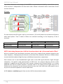
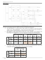
One of the milestones in the design of the MCR54 is unprecedented reliability: most of the circuitry
of the receiver is independent one from each other. Above a schematic with an overview of main
receiver functions.
RF layout:
For each antenna the RF signal is split in 4 to receiver 1,2,3 and 4 (antenna A and antenna B) with a
wide band splitter. Then 3 banks of filters are selected according to the frequency of the 4
receivers:
MCR54-B1 (UK)
MCR54-B2 (USA/EU)
MCR54-B3 (JP)
FILTER BANK 1:
470-800MHz Tuneable filter with 32MHz of bandwidth
FILTER BANK 2:
961-1000 MHz
823-832 MHz
806-810 MHz
FILTER BANK 3:
1045-1075 MHz
940-960 MHz
1240-1260 MHz
NOTE: the tuning frequencies of all the 4 receivers has to be in the same bank of filter!
All the 4 receivers are true diversity receivers: each one is made of two receivers tuned on the
same frequency. Subsequently the selection of the band filter between 100 kHz or 200kHz allows
to work with Narrowband (High Density) or Wideband transmitters respectively.
Each receiver has its own demodulated signal and its own RSSI signal (Receiver Signal Strength
Indication); RF squelch used measurement of RSSI level for antenna diversity and for audio
enabling. In addition to the RSSI level, each receiver measures the Channel Quality. It is a more
powerful tool than RF squelch because it actually looks at the quality of the signal from the TX
relative to the noise floor on the channel which can vary over time. With the noise squelch set to
on you can set the RF squelch to a much lower level.
A DSP selects or combines signals from section A & B to have the best audio.

MCR54 User Manual
4
Audio Layout
As shown on the above schematic, MCR54 provides the following audio signals:
HP [HEADPHONE]: an analog monitor audio output to headphone 3.5mm jack socket.
Thanks to the “Setup>Headphone” menu the user can select which of the 4 receivers he
wants to listen to and can adjust the volume from 0 to -24 step 1dB.
BOT [MAIN]: 4 audio signal streams come out in the connector on the bottom and
depending on the plugged slot-in can be configured according to the following table:
Slot in (SLK54-IK/SX)
BASE outputs (on BPA54)
CH1
CH2
CH1
CH2
CH3
CH4
AES3 en.
None
An [RXi]
An [RXi]
An [RX1]
An [RX2]
An [RX3]
An [RX4]
AUX
An [RXi]
An [RXi]
An [RX1]
An [RX2]
An [RX3]
An [RX4]
MAIN
(Base
outputs)
AES**
[RX1+RX2]
AES**
[RX3+RX4]
AES
[RX1+RX2]
AES
[RX3+RX4]
-
-
TOP [AUX]: 2 audio signal streams come out in the TA5 top feed connector and can be
configured in digital (enabling AES3 on AUX outputs) or in analog
AUX (on TOP FEED)
CH1
CH2
AES3 en.
None
An [RXi]
An [RXi]
AUX
AES
[RX1+RX2]
AES
[RX3+RX4]
MAIN
(Base outputs)
An [RXi]
An [RXi]

MCR54 User Manual
5
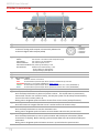
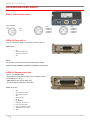
Product overview
❶
SMA antenna connectors
❷
Mini XLR 5-pin connector
2 channels analog audio outputs electronically balanced or
4 channels digital audio outputs (AES3)
1 GND
2 CHANNEL1+
3 CHANNEL1-
4 CHANNEL2+
5 CHANNEL2-
❸
LED power supply
GREEN The receiver is on with an external power supply
PALE GREEN The receiver is on with battery
GREEN BLINKING The external power is low
PALE GREEN BLINKING The power of the battery is low
RED BLINKING Relative transmitter battery is low:
- slowly blinking if 25% lifetime
- quickly blinking if 12% lifetime
❹
Led Bleutooth BLUE
❺
DISPLAY 128 x 96 pixels
❻
LED receiver status
OFF Relative receiver is not active
RED RF level below squelch and/or Noise squelch on both diversity receivers
RED BLINK frequency is out of filter (32MHz) see NOTE page 3
GREEN RF level above squelch and/or Noise squelch and receiver A is active (ANTENNA A)
BLUE RF level above squelch and/or Noise squelch and receiver B is active (ANTENNA B)
❼
Headphone output (jack 3.5 mm)
❽
“PWR/EXIT” BUTTON
Push and keep this button to power on/off the receiver. The on/off status is permanently
memorized into the non-volatile memory, this way the system can be setup to automatically
turn on the receiver when power up.
During menu navigation push this button to exit from current menu (escape function).
❾
“MENU/SEL” BUTTON
Push this button to navigate function menu’s and to confirm the chosen setup.
❿
“Arrow down/SCAN” BUTTON
Push and keep this button to start the automatic scan.
During menu navigation push this button to move-down and select the previous item.
⓫
“Arrow up/SYNC” BUTTON
Push and keep this button to start a synchronization with a Wisycom transmitter (follow
instructions on display). Before starting synchronization IRDA must be enabled on Wisycom
transmitter.
During menu navigation push this button to move -up and select the previous item.
❷
❹
❸
❶
❼
❺
❶
❻
❻
❾
❽
⓫
❿

MCR54 User Manual
6
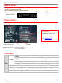
Display menu
Using navigation buttons it is possible to quick & easy navigate through the menu:
- SEL/Exit to enter or exit a level
- Arrow up/down to circle on the same level
- To save the modified parameters press and hold the SEL /MENU button ❾ until appears the
message "SAVED!".
Status screen
Tree menu
Main
Preset
Active
Load
U01-Preset1/U02-Preset2/U03-Preset3…. U16-Preset16
Save
U01-Preset1/U02-Preset2/U03-Preset3…. U16-Preset16
Factory
Setup
Info
Supply/ Model / Serial / Range / Base / HW/ FW / Diagnostic / Alarms
Bluetooth
Pwr on
No/Yes
Group
Channel
Frequency
Audio Modulation Bar
(from -42 to 0 dB)
Peak deviation ≥ 56KHz
RF bar
(8 steps of 10dBµV,
from 10 to 80 dBµV)
TX Battery
Level
RX Number
WARNING!
RX Number and Rx red
LED blink if frequency is
out of filter (32MHz)
see NOTE page 3

MCR54 User Manual
7
Infrared:
By activating the infrared, you can connect the MCR54 to other devices (such as Wisycom
Transmitter MTP40S/MTP41S/MTH410/MTB40S o the programmer UPKmini)
Preset:
The preset menu has the following two submenus:
Act: that allows to verify the active preset
Load: that allows to reload up to 16 Preset
Save: that allows to save up to 16 Presets
Setup:
Select Setup menu to access to the main parameters setting.
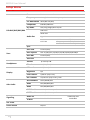
Info
In the info menu the following information are displayed:
Info
description
example
Supply
Supply voltage measured (on the rear connector)
12.0Volt
Model
MCR54
MCR54
Serial
The serial number composed by 1 letter+7 numbers
X3536539
Range
Frequency range according to the MCR54 band
(minimum and maximum frequency)
470--960
Base
Version of rear panel:
BPA54
SLK 54-SX
SLK 54-IK
BPA54
HW
Country
Country code
EU
Main rev.
Hardware revision of the main board
1
Main opt.
Option of the main board
-
RF rev.
Hardware revision of the RF board
2
RF opt.
Option of the RF board
-
Panel rev.
Hardware revision of the panel board
1
Panel opt.
Option of the panel board
-
Base rev.
Hardware revision of the Base (rear panel)
0
Base opt.
Option of the Base (rear panel)
-
FW
Version:
FW version
v2.0.5
BL:
Bootloader version
v.1.0.18
App:
Application version
v2.5d
DSP:
DSP version
v0.0.55r
Diagnostic
Alarms
Number of alarms.
If the number of alarms is > 0 push SEL button to enter on
the Alarms list. For each error a brief description and the
error code is showed.
0

MCR54 User Manual
8
Setup Menu
Active RXs
RX1 RX2 RX3 RX4
Edit RX1/RX2/RX3/RX4
Name
"8 characters max"
Frequency
Group / Channel and Frequency selection
Ch. Modulation
Wide/Narrow (HD)
Compander
ENR Wis/ENC Wis…
Sq. mode
OFF/Long Range/Normal/User
Audio Out
LINE level
AES3 level
Sign. Phase
Cal. Tone
Cal Tone
OFF/ON
Frequency
400/600/1000 Hz
Level
-30 to 0 dB (1 dB step)
Sync
Scan
Scan now
Channel/Freq
Scan squelch
OFF- 0/3/6/9/12/15/18/21/24/28/32/36/40/46 dBμV
Scan BNT
Channel/Freq
View last
Headphones
Volume
0/-24 step 1dB
RX sel
RX1/RX2/RX3/RX4
Display
LED mode
Full/Alarm/OFF
Brightness
0/5
Low Timeout
5/60 sec (step 5 sec)
OFF Timeout
10/120 sec (step 10 sec) / OFF
Adv. Audio
AES3 enabled
None/MAIN/AUX
AUX1
RX1/RX2/RX3/RX4
AUX2
RX1/RX2/RX3/RX4
AUX1 level
18dBu/-24dBu step 1dB
AUX2 level
18dBu/-24dBu step 1dB
Signalling
Audio off
RX1 RX2 RX3 RX4
visible only with
SLK54-IKSS
TX Batt.
RX1 RX2 RX3 RX4
Act. Code
Panel locked
No/Yes

MCR54 User Manual
9
Power on
Allow to enable/disable each single receivers:
Edit RX (same menu for each of the 4 receivers)
Edit RX: Name
Selecting Name, it’s possible to edit the name of the receiver (12 characters). The number of visible
characters depends on the type of characters used (uppercase or lowercase characters).
Edit RX: Frequency
Select current group and channel. If the specific group/channel is not locked, frequency can be
edited in this menu.
Edit RX: Channel modulation
Narrowband or Wideband software selectable according to transmitter modulation.
NOTE: During the SYNC process the receiver sends the type of modulation (NB or WB) and the TX adapts
automatically to the receiver’s modulation settings accordingly.
Edit RX: Compander
MCR54 supports 5 different type of “Compander systems” (others on request through Digicom)
ENS: designed for voice and music applications
ENR-Wisy: designed for maximum noise reduction. Ideal for use in louder environments.
ENC-Wisy: designed for maximum audio fidelity (use this in case of special vocal application or to
remote instruments). Ideal for use in quite environments.
ENR-1.2*/ENC-1.2*: to use with some type of camera (ex. Canon® C300, Canon® XF305, Sony®
Pmw200, Sony® Pmw300, Sony® PmwF5, Sony® Fs7, Nikon® D600 or Nikon® D800,
Canon® SD mark3...) which accept a signal with reduced dynamic. This type of expansion
doesn't add artifacts to the signal and allows to have a less noisy signal. It allows to
improve the quality of the audio registration (compared to the ENR/ENC standard)
increasing the S/N ratio up to 15dB.
To use these expanders, it’s necessary to set ENR on the transmitter and ENR 1.2 on the
receiver or set ENC on the transmitter and ENC 1.2 on the receiver.
ENR-1.2 it’s used for the optimization of noise, ENC-1.2 it’s used to optimize the voice.
NOTE: The compander of the receiver must be the same as the transmitter
MCR54 core is a power digital audio processor that, besides an unbeatable audio quality and
flexibility, can emulate most expanders systems on the market. On this menu you can setup the

MCR54 User Manual
10
audio expanding chipset emulation. ENR is emulating the Philips™ SA572 and PTT digital data of
Wisycom transmitters. Other setups can be loaded on request.
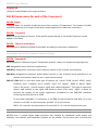
Edit RX: Sq. Mode
Squelch Mode is available in 3 possible configurations: Normal, Long Range or OFF.
Relevant setup are summarized in the following table:
FIXED PARAMETERS
RF squelch
[dBµV]
Noise
Squelch [dB]
Squelch ON
delay [ms]
Tone squelch
TSQ delay
[ms]
Normal
6
11
0
ON
500
Long
Range
3
8
0
OFF
500
OFF
OFF
0
0
OFF
500
NOTE: For expert users, there is an 4
th
configuration named User which allows to modify each
single parameter using the Wisycom Manager.
VARIABILE PARAMETERS
RF squelch
[dBµV]
Noise Squelch
[dB]
Squelch
ON delay
[ms]
Tone squelch
TSQ delay
[ms]
User
OFF/0/3/6…
/46
From 0 to 30
0 to 2000
ON/OFF
0 to 2000
RF Squelch
RF squelch is a function that acts to suppress the audio output of a receiver in the absence of a sufficiently
strong desired input signal.
Noise Squelch
Noise squelch is a more powerful tool than RF squelch because it actually looks at the quality of the signal from
the TX relative to the noise floor on the channel which can vary over time. With the noise squelch set to ON
you can set the RF squelch to a much lower level.
Tone Squelch
MCR54 is able to detect a digital tone squelch generated by a Wisycom transmitters (ex.
MTH410/MTH400/MTP40S/ MTP41S/MTB40S/RPU500).
Tone squelch ON: when the tone squelch is enabled the audio is muted unless the correct carrier is detected.
Tone squelch allows to work with lower RF squelch, increasing the coverage and the robustness especially in
presence of digital television carriers (DVB-T).
Edit RX: Audio Out
Max audio level output can be set:
from -24dBu to 18 dBu for analog output
from 0 to -30 dBFS step 1 for digital AES3 output

MCR54 User Manual
11
Edit RX> Audio Out: Sig. Phase
To change audio phase of 0 deg. or 180 deg.
Edit RX> Audio Out: Cal. Tone
If Cal. tone is enabled, a calibration tone is transmitted from the outputs of the receiver and the
audio LED of the relative RX become blue (to turn off the calibration tone, go on the menu
Advanced > RX and press EXIT)
It’s possible to select the audio level between -30dB to 0 dB (referred to the maximum output
level set on the audio outputs). It represent the reference of the peak deviation (56KHz).
The frequency of the tone can be chosen between 400/600/1000 Hz.
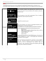
Edit RX: Sync
The SYNC function is useful to tune a transmitter on the same
frequency of the receiver via the IR interface. Before starting
the sync function tune the receiver on desired channel,
manually or using the SCAN utility. After this, enable the IR
interface on the transmitter. Now press UP&EXIT buttons
together or enter in the Sync menu to start the SYNC function.
Keep the IR window of the transmitter in front of the IR window of the receiver and, as soon as the
connection is done, the receiver will send to the transmitter all the information needed.
If the operation is not possible, (i.e. the frequency range of the transmitter is not compatible with
the frequency of the receiver), the display will show an error message.
If the transmitter has the function “NAME” enabled, when the sync function is completed it will
show the same name of the synchronized receiver.

MCR54 User Manual
12
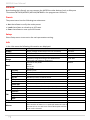
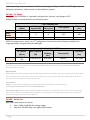
Scan
The MCR54 allows the user to scan using the Group/Channel frequency file in the unit or by
scanning a manual selection of frequencies. Select which type of scan by going into the scan menu.
Channel
Once started a channel scan operation the receiver asks for
group to be used*. Press and hold the SEL button to select the
group to scan.
Then it prompts to turn off all transmitters. This is in order to
provide the most accurate scan data.
Press SEL to start the scan!
After few seconds, scan results are displayed sorted by level,
making easier to pick up the best one.
The dotted line in the graph indicate the squelch threshold.
Under the graph are reported the following parameters:
- Ch: Channel
- Rank: Ranking position (Best/Lowest Noise Level to
Worst/Highest Noise Level)
- Freq: Frequency
- Lev: RF level
Pushing simultaneously UP and DOWN button, the results can
be also displayed on a chart in ascending order according to
the number of the channel.
After the selection of the desired channel, a screen appears
with the selected frequency, channel and group and it is
possible to Set or Synchronize the receiver with the
transmitter. We recommend setting the frequency and then
synchronize it with the transmitter.

MCR54 User Manual
13
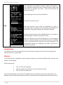
Headphones:
This menu the user can select which of the 4 receivers he wants to listen to and can adjust the
volume from 0 to -24 step 1dB.
Display:
In this menu item it’s possible to set the mode of switch on of the front LEDs and the contrast and
timeout of the display.
LEDs mode can be:
Full: all LEDs are activated
Alarm: the LEDs are ON only in case of alarm (only red)
OFF: all LEDs are always off
Low timeout indicates the time until the display stays on with the contrast set (after which, the
display contrast is lowered and after another “Low timeout” the display shows the Status screen).
Freq
The Frequency scan allows to select a range of frequency to
scan, between a maximum and a minimum value and the step
with which to perform the scans. Press and hold the SEL
button to confirm.
Then it prompts to turn off all transmitters.
Press SEL to start the scan!
After few seconds, scan results are displayed on a chart in
ascending order according to the frequency (step 1MHz). The
dotted line in the graph indicate the squelch threshold.
Pushing simultaneously UP and DOWN button it’s possible to
zoom the graph to show all the steps of scan
After the selection of the desired frequency, a screen appears
with the selected frequency and the RF level and it is possible
to Set or Synchronize the receiver with the transmitter. We
recommend setting the frequency and then synchronize it
with the transmitter.

MCR54 User Manual
14
Off timeout is the time until the display stays on (after which, the display will automatically turn
off). If Off timeout is set to OFF the display never turn off automatically.
Advanced audio:
This menu allows to decide the type of audio outputs (digital AES3 or analog) and what receivers
come out to the connectors.
Depending on the plugged slot-in it can be configured according to the following tables:
With BPA54 it is possible to enabled AES outputs on AUX (Top Feed) or on MAIN (Base outputs).
When AES is disabled (set to None) or enabled on AUX, analog Base outputs can be configured
with any combination of 2 receivers (RX1+RX2, RX2+RX3, …)
AUX (on TOP FEED)
BASE outputs (on BPA54)
1 GND
2 CHANNEL1+
3 CHANNEL1-
4 CHANNEL2+
5 CHANNEL2-
CH1
CH2
CH1
CH2
CH3
CH4
AES3 en.
None
An [RXi]
An [RXi]
An [RX1]
An [RX2]
An [RX3]
An [RX4]
AUX
AES
[RX1+RX2]
AES
[RX3+RX4]
An [RX1]
An [RX2]
An [RX3]
An [RX4]
MAIN
(Base outputs)
An [RXi]
An [RXi]
AES
[RX1+RX2]
AES
[RX3+RX4]
-
-
With SLK54-IK it is possible to enabled AES outputs on AUX (Top Feed) or on MAIN (Base Outputs).
When AES is disabled (set to None) or enabled on AUX, analog Base outputs can be configured
with any combination of 2 receivers (RX1+RX2, RX2+RX3, …)
AUX (on TOP FEED)
BASE outputs (on SLK54-IK)
2 CHANNEL1+
3 CHANNEL1-
15 CHANNEL2+
16 CHANNEL2-
1 GND
2 CHANNEL1+
3 CHANNEL1-
4 CHANNEL2+
5 CHANNEL2-
CH1
CH2
CH1
CH2
AES3 en.
None
An [RXi]
An [RXi]
An [RXi]
An [RXi]
AUX
AES
[RX1+RX2]
AES
[RX3+RX4]
An [RXi]
An [RXi]
MAIN
(Base outputs)
An [RXi]
An [RXi]
AES [RX1+RX2]
AES [RX3+RX4]

MCR54 User Manual
15
With SLK54-SX it is possible to enabled AES outputs only on AUX (Top Feed). Analog Base outputs
can be configured with any combination of 2 receivers (RX1+RX2, RX2+RX3, …)
AUX (on TOP FEED)
MAIN (on SLK54-SX)
2 CHANNEL1
3 CHANNEL2
1 GND
2 CHANNEL1+
3 CHANNEL1-
4 CHANNEL2+
5 CHANNEL2-
CH1
CH2
CH1
CH2
AES3
en.
None
An [RXi]
An [RXi]
An [RXi]
An [RXi]
AUX
AES [RX1+RX2]
AES [RX3+RX4]
An [RXi]
An [RXi]

MCR54 User Manual
16
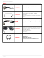
ACCESSORIES AND PARTS
BPA54: Stand alone socket
Hirose HR10A-F
1 GND
4 +VDC
1 GND
2 CHANNEL1+
3 CHANNEL1-
4 CHANNEL2+
5 CHANNEL2-
1 GND
2 CHANNEL3+
3 CHANNEL3-
4 CHANNEL4+
5 CHANNEL4-
SLK54-SX: Sony slot-in
"Slot-in" kit (upper flange +rear-panel) for Sony camera.
SUBD-15pin:
1 GND
2 CH1 Anal (unbalanced)
3 CH2 Anal (unbalanced)
4 VDC
NOTE:
not all Sony cameras has the internal double pin enable.
CHECK IF YOUR CAMERA SUPPORT 2 CHANNELS ON SLOT-IN
SLK54-IK: Ikegami super slot
“Slot-in” compatible with:
- Sound Device SuperSlot (4 audio outs in capable devices,
i.e. Soundevices™ SL-2)
- MRK16 Multi Slot rack (4 audio out)
- Unislot (Ikegami, Panasonic cameras1)
SUBD-25 pinout:
1 GND
2 CH1+ Anal/ CH1,2 AES3+
3 CH1- Anal/ CH1,2 AES3-
4 GND
5 VDC (6-18 VDC)
6 RX_ON
7 RX_WARNING
15 CH2+ Anal/ CH3,4 AES3+
16 CH2- Anal/ CH3,4 AES3-
22 UART from Wireless receiver
23 UART to Wireless receiver
25 GND

MCR54 User Manual
17
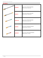
CABLES
CAM50-3
AF cable (50 cm), mini XLR-5F / 2 XLR-3M
connectors
CAM50-41
AF cable (50 cm), mini XLR-5F / 1 XLR-3M
connectors
Line 1 feed XL3-M (TO BE USED FOR AES3 CAMERA
INPUT)
CDC34
External power feeding cable, hirose/raw wires (50
cm)
PSP910-H
AC/DC Power Supply, Switch Mode with Hirose 4 pin
connector (to use one “desktop” apparatus alone)
Input:100 ÷ 240V ac
Ouput:12V@700mA, 8W
Plug type: EU
CAUSBC1
USB Cable 1m
USB B - USB C Male Black
To monitor/control/power on MCR54 receiver

MCR54 User Manual
18
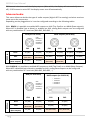
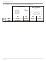
ANTENNAS
AWS-BK
Whip antenna UHF 470-608 MHz
SMA connector, black cap
AWS-YL
Whip antenna UHF 572-694 MHz
SMA connector, yellow cap
AWS-GN
Whip antenna UHF 670-870 MHz
SMA connector, green cap
AWS-BL
Whip antenna UHF 820-1160 MHz
SMA connector, blue cap
AWS-RD
Whip antenna UHF 1060-1300 MHz
SMA connector, red cap

MCR54 User Manual
19
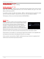
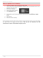
How to update the firmware:
1. Connect the MCR54 to the PC through the USB-C cable
2. Check if the version of Wisycom Manager installed in your PC is the latest version. If not,
upgrade to the new version
3. Run Wisycom Manager
4. Power up the receiver MCR54
5. Push FW UPDATE button
6. Download the .xupf file from the website and load the file using FW library > Import
button.
7. Select the file
8. Select the receiver and Play
First the program erases the flash memory and later it writes the flash memory. A green bar below
the panel shows the progress of this process. Take care do not disconnect the USB
communication or power off the MCR54 during this process.
La pagina si sta caricando...
La pagina si sta caricando...
La pagina si sta caricando...
La pagina si sta caricando...
-
 1
1
-
 2
2
-
 3
3
-
 4
4
-
 5
5
-
 6
6
-
 7
7
-
 8
8
-
 9
9
-
 10
10
-
 11
11
-
 12
12
-
 13
13
-
 14
14
-
 15
15
-
 16
16
-
 17
17
-
 18
18
-
 19
19
-
 20
20
-
 21
21
-
 22
22
-
 23
23
-
 24
24


in altre lingue
- English: WisyCom MCR54 User manual
Documenti correlati
-
WisyCom MCR54 Manuale utente
-
-
-
-
-
-
-
-
-

