
AMG Systems Ltd. reserves the right to make changes to this document without
notice. The information herein is believed to be accurate. No responsibility is
assumed by AMG for its use.
Page 1of 8 AMG2744-DR Instruction
Sheet D15691-00
AMG2744-DR
Instruction Manual
Four Channel Video Receive Unit with Bi-directional Data
With Dual Redundant Operation on a dual fibre ring
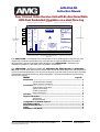
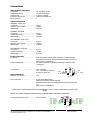
The AMG2744-DR is a standalone four channel video receive unit designed to ‘drop off’ four video
signals from a dual fibre optical fibre ring. It also provides a single RS485/RS422 or RS232 bi-
directional data channel to the video insert outstations. The AMG2744-DR is designed to be
standalone mounted on a backplate in the orientation shown above.
The AMG2744-DR is designed to operate with AMG2783-1-DR,AMG2783-2-DR and AMG2783-4-
DR, single channel, dual channel and 4 channel video and bi-directional data insert units respectively
or their rackmount equivalents. Each receiver will ‘drop off’ up to four video channels which are being
transmitted around the dual fibre ring. When used with a 4-channel transmitter the ring becomes a
point to point system.
Index Page No.
Introduction.......................................................................................................... 2
Unit Functional Schematic................................................................. 2
Optical System Connection............................................................... 2
Connections ......................................................................................................... 5
Video Output connections ................................................................. 5
Optical Connections.......................................................................... 5
Power Connections ........................................................................... 5
Data Connections.............................................................................. 6
Indicators ........................................................................................................... 7
Physical Information ........................................................................................... 7
Dimensions........................................................................................ 7
Mounting Details................................................................................ 7
Configuration of the Data Channel ....................................................................7
SW1 Switch Settings ........................................................................................... 8
Removal from the Case....................................................................................... 8
Safety ........................................................................................................... 9
Maintenance and Repair ..................................................................................... 9
167mm Overall
155mm between mounting slot centres
(4mm slots)
122mm between
Slot Centres
132mm Overall
AMG
2744
-
DR
4 CHANNEL VIDEO
RECEIVER UNITS
+
BI-DIRECTIONAL
DATA
PRIMARY
TX O O
RX
FRONT PANEL INDICATORS
VIDEO PRESENT
CH 1 CH2
O O
CH 3 CH4
O O
POWER
O O
GND
+12-16 Volts dc
REAR PANEL CONNECTIONS
OPTO
IN
GND
OUT-
OUT+
IN-
IN+
DATA
CONNECTIONS
RS 422
OR
RS 485
*
TX
O O
RX
DATA PRESENT
VIDEO
CH 1
OPTO
OUT
OPTO
IN
OPTO
OUT CH 4
CH 2
CH 3
DATA
POWER POWER
OPTO
P
R
I
M
A
R
Y
SECONDARY
TX O O
RX
S
E
C
O
N
D
A
R
Y

AMG Systems Ltd. reserves the right to make changes to this document without
notice. The information herein is believed to be accurate. No responsibility is
assumed by AMG for its use.
Page 2of 8 AMG2744-DR Instruction
Sheet D15691-00
Introduction
Unit Functional Schematic
The AMG2744 DR receives a 1310nm optical signal from
both a primary and secondary fibre input. It drops off up
to 4 video signals and a combined data signal
transmitted from AMG2783-n-DR insert units and
transmits out a single data channel back to the insert
units on a 1310nm optical signal.
In normal operation where connection of both the
previous unit and the subsequent unit are OK, the video
and data signal is taken from the primary input and the
data transmitted out on the primary output. The
secondary optical input is independent and is
regenerated on the secondary output.
If the primary input signal is not present, the unit will shut down the secondary output to inform the
previous unit that the signal route is not OK. The previous unit will then send out the video and data
signal on its secondary output. This signal will be repeated around the ring to get back to this
AMG2744-DR on the secondary route. As the primary input is not present on this unit, the video and
data signal will now be taken from the secondary optical input. Thus maintaining integrity of the video
and data transmission.
If the secondary input signal is not present, the unit will assume that the route to the next unit is not
OK and send out the return data signal on the secondary optical output. This return data will be
transmitted to the next unit around the ring in the opposite direction on the secondary route.
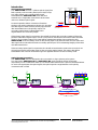
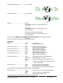
Optical System Connection
The AMG2744-DR units are designed to be connected in a ring or point to point system.
In a ring system AMG2783-1-DR and AMG2783-2-DR, single and dual channel insert units
respectively can be combined to make up a 4 channel video transmission system as illustrated below.
As each unit regenerates the optical signal, the optical dynamic range between each optically
connected node is 17dB.
2744-DR
2700 optics (Primary)
TXRX
2700 optics
(Secondary) RXTX
1310nm
1310nm 1310nm
1310nm
4 Video Outputs 1 Data I/O
PRIMARY
OPTO IN
Primary Signal Direction
Secondary Signal Direction
SECONDARY
OPTO OUT PRIMARY
OPTO OUT
SECONDARY
OPTO IN
( to primary input and
secondary output of next
2783-1,2,4.
( From primary output and
secondary input of previous
2783-1,2,4-DR.
1
3
4
2
1
4
3
2
Primary Optical Fibre
Secondary Optical Fibre
Two Optical Fibres
AMG
2744-DR
4CH ANNELVIDEO
RECEIVERUNIT
+
BI-DIRECTIONAL
DATA
PRIMARY
TX OO RX
OPTOSYNC
FRONTPANEL I NDICATORS
VIDEOPRESENT
CH1 CH2
OO
CH3 CH4
OO
POWER
O OGND
+12-16Vo ltsd c
REAR PANEL CONNECTIONS
OPTOIN
GND
OUT-
OUT+
IN-
IN+
DATA
CONNECTIONS
RS422OR
RS485
*
TX
O O
RX
DATAPRESENT
VIDEO
CH 1
OPTO
OUT
OPTO
IN
OPTO
OUT CH4
CH 2
CH3
DATA
POWER POWER
OPTOP
R
I
MA
R
Y
SECONDARY
TX OO
RX
OPTOSYNC
S
E
C
O
ND
A
R
Y
AMG
2783-1-DR
1CHANNEL VIDEO
INSERT UNIT
+
BI-DIRECTIONAL
DATA
PRIMARY
TX OO
RX
OPTOSYNC
FRONTPANE L INDICATORS
VIDEOPRESE NT
CH1 CH2
O O
CH3 CH4
O O
POWER
O OGND
+12-16 Volts dc
REAR PANEL CONNECTIONS
OPTO
IN
GND
OUT-
OUT+
IN-
IN+
DATA
CONNECTIONS
RS422
OR
RS485
*
TXO ORX
DATA PRESENT
VIDEO
CH1
OPTO
OUT
OPTO
IN
OPTO
OUT CH4
CH2
CH3
DATA
POWER POWER
OPTO P
R
I
MA
R
Y
SECONDARY
TX OO RX
OPTO SYNC
S
E
C
O
ND
A
R
Y
AMG
2783-1-DR
1CHANNEL VIDEO
INSERT UNIT
+
BI-DIRECTIONAL
DATA
PRIMARY
TX OO
RX
OPTOSYN C
FRONTPAN EL INDICATORS
VIDEOPRESE NT
CH1 CH2
O O
CH3 CH4
O O
POWER
O OGND
+12-16 Volts dc
REAR PANEL CONNEC TIONS
OPTO
IN
GND
OUT-
OUT+
IN-
IN+
DATA
CONNECTIONS
RS422OR
RS485
*
TXO ORX
DATA PRESENT
VIDEO
CH1
OPTO
OUT
OPTO
IN
OPTO
OUT CH4
CH2
CH3
DATA
POWER POWER
OPTOP
R
I
MA
R
Y
SECONDARY
TX O ORX
OPTO SYNC
S
E
C
O
ND
A
R
Y
AMG
2783-2-DR-SF
2 CHANNEL VIDEO
INSERTUNIT
+
BI-DIRECTIONAL
DATA
PRIMARY
TX O OR X
OPTOSYNC
FRONTPANEL INDICATOR S
VIDEOPRESENT
CH1 CH2
OO
CH3 CH4
OO
POWER
O O
GND
+12-16Volts dc
REARPA NEL CONNECTIONS
OPTO
IN
GND
OUT-
OUT+
IN-
IN+
DATACONNECTIONS
RS422
OR
RS485
*
TXO OR X
DATAPRESENT
VIDEO
CH1
OPTOOUT
OPTO
IN
OPTO
OUT CH4
CH2
CH3
DATA
POWER POWER
OPTOP
R
IM
A
R
Y
SECONDARY
TX OO
RX
OPTOSYNC
S
EC
O
N
D
A
R
Y

AMG Systems Ltd. reserves the right to make changes to this document without
notice. The information herein is believed to be accurate. No responsibility is
assumed by AMG for its use.
Page 3of 8 AMG2744-DR Instruction
Sheet D15691-00
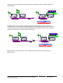
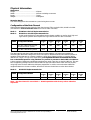
If a fibre link is broken, operation of the ring continues by making use of the secondary optical fibre
route as below:
If multiple breaks occur, operation is maintained will all the units still physically connected to the
receiver. For the scenario shown below camera signals and control would now be lost from cameras 1,
2 and 3 as there is now no physical connection between the transceivers and the receiver. However
operation of cameras 4,5,6,7 and 8 remains fully functional.
Note that where necessary repeaters can be added at nodes to increase the average distance
between nodes.
1
3
4
2
1
4
3
2
Primary Optical Fibre
Secondary Optical Fibre
Two Optical Fibres
AMG
2744-DR
4CH ANNELVIDEORECEIVERUNIT
+
BI-DIRECTIONAL
DATA
PRIMARY
TX OO RX
OPTOSYNC
FRONTPANEL I NDICATORS
VIDEOPRESENT
CH1 CH2
OO
CH3 CH4
OO
POWER
O OGND
+12-16Vo ltsd c
REAR PANEL CONNECTIONS
OPTO
IN
GND
OUT-
OUT+
IN-
IN+
DATA
CONNECTIONS
RS422OR
RS485
*
TX
O O
RX
DATAPRESENT
VIDEO
CH 1
OPTO
OUT
OPTO
IN
OPTO
OUT CH4
CH 2
CH3
DATA
POWER POWER
OPTOP
R
I
MA
R
Y
SECONDARY
TX OO
RX
OPTOSYNC
S
E
C
ON
D
A
R
Y
AMG
2783-1-DR
1CHANNEL VIDEO
INSERT UNIT
+
BI-DIRECTIONAL
DATA
PRIMARYTX OO
RX
OPTOSYNC
FRONTPANE L INDICATORS
VIDEOPRESE NT
CH1 CH2
O O
CH3 CH4
O O
POWER
O OGND
+12-16 Volts dc
REAR PANEL CONNECTIONS
OPTO
IN
GND
OUT-
OUT+
IN-
IN+
DATA
CONNECTIONS
RS422
OR
RS485
*
TXO ORX
DATA PRESENT
VIDEO
CH1
OPTOOUT
OPTO
IN
OPTO
OUT CH4
CH2
CH3
DATA
POWER POWER
OPTO
P
RI
M
A
R
Y
SECONDARYTX OO RX
OPTO SYNC
S
E
CO
N
D
A
RY
AMG
2783-1-DR
1CHANNEL VIDEOINSERT UNIT
+
BI-DIRECTIONAL
DATA
PRIMARY
TX OO
RX
OPTOSYN C
FRONTPAN EL INDICATORS
VIDEOPRESE NT
CH1 CH2
O O
CH3 CH4
O O
POWER
O OGND
+12-16 Volts dc
REAR PANEL CONNEC TIONS
OPTO
IN
GND
OUT-
OUT+
IN-
IN+
DATA
CONNECTIONS
RS422O R
RS485
*
TXO ORX
DATA PRESENT
VIDEO
CH1
OPTOOUT
OPTO
IN
OPTO
OUT CH4
CH2
CH3
DATA
POWER POWER
OPTOP
R
IM
A
R
Y
SECONDARY
TX O ORX
OPTO SYNC
S
E
CO
N
D
A
R
Y
AMG
2783-2-DR-SF
2 CHANNEL VIDEO
INSERTUNIT
+
BI-DIRECTIONAL
DATA
PRIMARY
TX O OR X
OPTOSYNC
FRONTPANEL INDICATOR S
VIDEOPRESENT
CH1 CH2
OOCH3 CH4
OO
POWER
O OGND
+12-16Volts dc
REARPA NEL CONNECTIONS
OPTO
IN
GND
OUT-
OUT+
IN-
IN+
DATA
CONNECTIONS
RS422
ORRS 4 85
*
TXO OR X
DATAPRESENT
VIDEO
CH1
OPTO
OUT
OPTOIN
OPTO
OUT CH4
CH2
CH3
DATA
POWER POWER
OPTO
PR
I
M
A
R
Y
SECONDARY
TX OO
RX
OPTOSYNC
SE
C
O
N
DA
R
Y
1
3
4
2
1
4
3
2
Primary Optical Fibre
Secondary Optical Fibre
Two Optical Fibres
AMG
2744-DR
4CH ANNELVIDEO
RECEIVERUNIT
+
BI-DIRECTIONAL
DATA
PRIMARY
TX OORX
OPTOSYNC
FRONTPANEL I NDICATORS
VIDEOPRESENT
CH1 CH2
O OCH 3 CH4
O O
POWER
O O
GND
+12-16Vo ltsd c
REAR PANEL CONNECTIONS
OPTO
IN
GND
OUT-
OUT+
IN-
IN+
DATACONNECTIONS
RS422
OR
RS485
*
TX
O O
RX
DATAPRESENT
VIDEO
CH 1
OPTO
OUT
OPTO
IN
OPTO
OUT CH4
CH 2
CH3
DATA
POWER POWER
OPTOP
RI
M
A
R
Y
SECONDARY
TX O O
RX
OPTOSYNC
S
EC
O
N
D
AR
Y
AMG
2783-1-DR
1CHANNEL VIDEO
INSERT UNIT
+
BI-DIRECTIONAL
DATA
PRIMARY
TX OO
RX
OPTOSYNC
FRONTPANE L INDICATORS
VIDEOPRESE NT
CH1 CH2
OOCH3 CH4
OO
POWER
O O
GND
+12-16 Volts dc
REAR PANEL CONNECTIONS
OPTO
IN
GND
OUT-
OUT+
IN-
IN+
DATACONNECTIONS
RS422
OR
RS485
*
TXO ORX
DATA PRESENT
VIDEO
CH1
OPTO
OUT
OPTOIN
OPTO
OUT CH4
CH2
CH3
DATA
POWER POWER
OPTOP
R
I
M
A
RY
SECONDARY
TX OORX
OPTO SYNC
SE
C
O
N
DA
R
Y
AMG
2783-1-DR
1CHANNEL VIDEO
INSERT UNIT
+
BI-DIRECTIONAL
DATA
PRIMARY
TX O O
RX
OPTOSYN C
FRONTPAN EL INDICATORS
VIDEOPRESE NT
CH1 CH2
OOCH3 C H4
OO
POWER
O OGND
+12-16 Volts dc
REAR PANEL CONNEC TIONS
OPTO
IN
GND
OUT-
OUT+
IN-
IN+
DATACONNECTIONS
RS422
OR
RS485
*
TXO ORX
DATA PRESENT
VIDEO
CH1
OPTO
OUT
OPTOIN
OPTO
OUT CH4
CH2
CH3
DATA
POWER POWER
OPTO
PR I
M
A
RY
SECONDARY
TX OO RX
OPTO SYNC
SE
C
O
N
DA
R
Y
AMG
2783-2-DR-SF
2 CHANNEL VIDEO
INSERTUNIT
+
BI-DIRECTIONAL
DATA
PRIMARY
TX OO R X
OPTOSYNC
FRONTPANEL INDICATOR S
VIDEOPRESENT
CH1 CH2
OOCH3 CH4
OO
POWER
O OGND
+12-16Volts dc
REARPA NEL CONNECTIONS
OPTO
IN
GND
OUT-
OUT+
IN-
IN+
DATA
CONNECTIONS
RS422
OR
RS485
*
TXO OR X
DATAPRESENT
VIDEO
CH1
OPTO
OUT
OPTO
IN
OPTOOUT CH 4
CH2
CH3
DATA
POWER POWER
OPTOP
R
I
M
AR
Y
SECONDARY
TX OO
RX
OPTOSYNC
S
E
C
O
ND
A
R
Y

AMG Systems Ltd. reserves the right to make changes to this document without
notice. The information herein is believed to be accurate. No responsibility is
assumed by AMG for its use.
Page 4of 8 AMG2744-DR Instruction
Sheet D15691-00
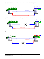
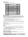
The AMG2744(R)-DR is connected as illustrated below when used with an AMG2783(R)-4-DR 4
channel insert unit.
Again if one of the routes is broken, operation of the system is maintained as shown below:
Or:
1
3
4
2
1
3
2
4
2784R-DR
AMG
PRIMARYOPTO SY NC
TXO ORX SECONDARY OPTO S YNC
TXO ORX
VIDEOPRE SENT
CH1 O O CH2
CH3 O O CH4
CH1 O O R X
DATA PRESENT
-------------------------
8CH VIDEO RX
+
DATATX/RX
POWER
O
POWER
O
VIDEOPRE SENT
CH5 O O CH6
CH7 OCH8
CH1 OO RX
DATA PRESENT
+
Secondary Optical Fibre
Primary Optical Fibre
2783R-DR
AMG
PRIMARY OPTOSYNC
TX
O
O
RX
SECONDARYOPTO SYNC
TX
O
O
RX
VIDEOPRESENT
CH1
O O
CH2
CH3
O O
CH4
CH1
O O
RX
DATAPRESENT
-------------------------
8 CH VIDEO RX
+
DATATX/RX
POWER
O
POWER
O
VIDEOPRESENT
CH5
O O
CH6
CH7
O
CH8
CH1
O
O
RX
DATAPRESENT
+
1
3
4
2
1
3
2
4
2784R-DR
AMG
PRIMARYOPTO SY NC
TX O O RX SECONDARYOPTOS YNC
TXO ORX
VIDEOPRE SENT
CH1 OO CH2
CH3 OO CH4
CH1 O O R X
DATA PRESENT
-------------------------
8CH VIDEO RX
+
DATATX/RX
POWER
O
POWER
O
VIDEOPRE SENT
CH5 O O CH6
CH7 OCH8
CH1 O O RX
DATA PRESENT
+
Secondary Optical Fibre
Primary Optical Fibre
2783R-DR
AMG
PRIMARY OPTOSYNC
TX
O
O
RX
SECONDARYOPTO SYNC
TX
O
O
RX
VIDEOPRESENT
CH1
O O
CH2
CH3
O O
CH4
CH1
OO
RX
DATAPRESENT
-------------------------
8 CH VIDEO RX
+
DATATX/RX
POWER
O
POWER
O
VIDEOPRESENT
CH5
O O
CH6
CH7
O
CH8
CH1
O
O
RX
DATAPRESENT
+

AMG Systems Ltd. reserves the right to make changes to this document without
notice. The information herein is believed to be accurate. No responsibility is
assumed by AMG for its use.
Page 5of 8 AMG2744-DR Instruction
Sheet D15691-00
OPTO IN D
A
T
A
CH 8 CH 4
OPTO OUT
Channels 1 to 4
Pin 5 – Ground
Pin 4 – Data Out –
Pin 3 – Data Out +
Pin 2 – Data In –
Pin 1 – Data In +
Channels 5 to 8
Pin 5 – Ground
Pin 4 – Data Out –
Pin 3 – Data Out +
Pin 2 – Data In –
Pin 1 – Data In +
D
A
T
A
Connections
Video Output Connections
Connector ...........................................75 ohm BNC Socket.
Output Impedance...............................75 ohm terminated.
Output Level........................................1 volt p-p nominal
Frequency Response ..........................10Hz to 5.75MHz min.
No of channels.....................................4
Optical Connections
PRIMARY OPTO OUT
Connector............................................FC/PC
Optical Launch Power .........................-5dBm
Wavelength..........................................1310nm
PRIMARY OPTO IN
Connector............................................FC/PC
Optical Sensitivity................................-22dBm
Wavelength..........................................1310nm
SECONDARY OPTO OUT
Connector............................................FC/PC
Optical Launch Power .........................-5dBm
Wavelength..........................................1310nm
SECONDARY OPTO IN
Connector............................................FC/PC
Optical Sensitivity................................-22dBm
Wavelength..........................................1310nm
Power Connection
Connector............................................2off removable screw terminal connector (3.5mm spacing)
Manufacturers Part No. Phoenix/Combicom MC1-5/2-ST-3.5
AMG Part No.G00047-00
Power requirement ..............................12 volt to 16 volt DC @ 800mA combined current for both
connectors
Connections.........................................See schematic
+12 – 16 Volts on lower pin
0 Volts on upper pin
Data Connections
Number of Channels............................One
Data Connector ...................................5 way removable spring
terminal connector (2.5mm spacing)
Manufacturers Part No. Phoenix/Combicom FK-MC-0.5/5-ST-
2.5
AMG Part No G15098-00
SW1 used to select between RS232 and RS485/422, SW2 is used to select between RS422 and
RS485.
NOTE: The unit is shipped from the factory as RS422 unless otherwise requested.
Connections RS422 4 wire..................See schematic
OPTO IN D
A
T
A
CH 8 CH 4
OPTO IN 0 Volts
+12 – 16 Volts
0 Volts
+12 – 16 Volts

AMG Systems Ltd. reserves the right to make changes to this document without
notice. The information herein is believed to be accurate. No responsibility is
assumed by AMG for its use.
Page 6of 8 AMG2744-DR Instruction
Sheet D15691-00
Connections RS485 2 wire..................See schematic
Connections RS232.............................See schematic
Protocol................................................RS232
SW1 switch position 9 on, switch position 10 on
SW2 all off
RS485 2wire
SW1 switch position 9 off, switch position 10 off
SW2 see below
RS422 4 wire Bus’ed or point to point
SW1 switch position 9 off, switch position 10 off
SW2 see below
See below for Configuration of the RS485 / RS422 data channel and description of tristate
operation
Each of the two data channels can be set up independently.
Indicators
Power...................................................Green – unit powered
Off – no power applied to unit
Primary Opto Sync TX.........................Green - optical channel transmitting
Off - optical channel not transmitting
Primary Opto Sync RX ........................Green - optical channel receiving
Off - optical channel not receiving
Secondary Opto Sync TX....................Green - optical channel transmitting
Off - optical channel not transmitting
Secondary Opto Sync RX....................Green - optical channel receiving
Off - optical channel not receiving
Video Present CH1-4...........................Green – video signal present on video output BNC
Red/Green - Channel present , no video
Red - Fibre Loop Present, no TX selected on this
channel
Off – no Fibre Loop Present thus no video present on
video channel BNC
Data Present TX ..................................Green – logic one present on the data input
Red – logic zero present on the data input
Off – tri-state off or no connection on the data input
This represents the data signals being transmitted on the optical fibre
Data Present RX..................................Green – logic one present on the corresponding data
output
Red – logic zero present on the data output
Off – tri-state off on the data output
This represents the data signals being received on the optical fibre
OPTO IN D
A
T
A
CH 8 CH 4
OPTO OUT
Channels 1 to 4
Pin 5 – Ground
Pin 4 – No Connection
Pin 3 – RS232 Data Output
Pin 2 – No Connection
Pin 1 – RS232 Data Input
D
A
T
A
Channels 5 to 8
Pin 5 – Ground
Pin 4 – No Connection
Pin 3 – RS232 Data Output
Pin 2 – No Connection
Pin 1 – RS232 Data Input
A
T
A
CH 8 CH 4
OPTO OUT
Channels 1 to 4
Pin 5 – Ground
Pin 4 – No Connection
Pin 3 – No Connection
Pin 2 – Data In/Out –
Pin 1 – Data In/Out +
D
A
T
A
Channels 5 to 8
Pin 5 – Ground
Pin 4 – No Connection
Pin 3 – No Connection
Pin 2 – Data In/Out –
Pin 1 – Data In/Out +

AMG Systems Ltd. reserves the right to make changes to this document without
notice. The information herein is believed to be accurate. No responsibility is
assumed by AMG for its use.
Page 7of 8 AMG2744-DR Instruction
Sheet D15691-00
Physical Information
Dimensions
Height ..................................................132mm
Width....................................................167mm excluding connectors
Depth ...................................................70mm
Weight..................................................1000grams
Mounting Details
The unit is designed to be mounted on a panel using 4mm screws.
Configuration of the Data Channel
SW1 and SW2 determine the protocol of the data channel. This can be RS232, RS485 or RS422.
(See below for removal from the case and access to SW1 and SW2)
Mode 1 – RS485 two wire half duplex transmission.
Mode 2 – RS422 four wire full duplex transmission.
In this mode the RS422 output will transmit a tristate condition as well as logic high and
logic low for systems which require bus-ing of the RS422 four-wire connection.
MODE Configuration Details SW2
position
1
SW2
position
2
SW2
position
3
SW2
position
4
SW1
position
9
SW1
position
10
1 RS-422 4 wire Point-to-Point -
and RS-422 BUS system OFF OFF OFF OFF OFF OFF
2 RS-485 2 wire BUS systems OFF ON ON ON OFF OFF
The data input for both the RS485 and the RS422 modes detects a tri-state input condition by
monitoring the differential voltage level across the input. A differential level below 500mV positive or
negative will be detected as a tristate condition. A level above 500mV positive or negative will be
detected as a logic 1 or logic zero respectively. It is important therefore to terminate the RS485
bus or the RS422 input bus using 120ohms if a pre-bias is present on the RS485 or RS422 bus.
A large number of third party equipment manufacturers apply a pre-bias on their RS485 bus. This pre-
bias is applied by pulling one arm of the RS485 bus high (+5 volts) and the other arm low (0 volts)
using high value resistors within the third party equipment. In order to ensure that the AMG2700
equipment detects a tri-state condition, then these resistors should have a value above 1kohm.
Mode 3 – RS232 full duplex transmission.
MODE Configuration Details SW2
position
1
SW2
position
2
SW2
position
3
SW2
position
4
SW1
position
9
SW1
position
10
3 RS-232 Point to Point OFF OFF OFF OFF ON ON
Note: - the data channel is set at Mode 1 – RS422 operation at the factory unless otherwise
requested.

AMG Systems Ltd. reserves the right to make changes to this document without
notice. The information herein is believed to be accurate. No responsibility is
assumed by AMG for its use.
Page 8of 8 AMG2744-DR Instruction
Sheet D15691-00
SW1 Switch Settings
All SW1 switch settings are set at the factory as follows:
Channels 1-4 Card
Switch
Position Description Setting
1 Video channel configuration OFF
2 Video channel configuration OFF
3 Video channel configuration OFF
4 Primary / Secondary Board Setting ON
5 Dual Redundant / Not dual redundant OFF
6 Master ON
7 Full Scale Calibration Output OFF
8 On board data / Separate data card ON
9 RS232 Select OFF for
RS485/422
10 RS232 Select OFF for
RS485/422
Removal from the Case
Note: - The 2700 PCB’s are static sensitive. Handle with proper care and use normal electrostatic
discharge (ESD) procedures. Use properly grounded protection (for example, wrist stamps) when
handling the PCB. The switch positions can be accessed without pulling out the boards from the case
fully. It is recommended that the boards are slid out just sufficient to access the switches (~40mm) in
order to reduce the possibility of damage to the optical fibres and electronic circuits.
In order to remove the case (to access SW1 and SW2)
1.1.Loosen and remove the four screws on the top and bottom of the unit’s rear panel.
1.2.Slide the PCB assembly connected to the rear panel out of the case.
1.3.Ensure that the optical fibre is not trapped.
SW1 and SW2 can be found on the bottom right hand corner of each board and are labelled, close to
the rear panel. The switch position are labelled on the switch, switch position 1 is always the furthest
from the edge of the PCB.
When re-inserting the main PCB into the housing take care not to trap the optical fibre or the board
interconnection cables.
Fasten the rear panel with the screws.
Safety
The 2700 series of products uses a Class 1 laser system in accordance with EN 60825-2:2000.
It is always advisable to follow good practice when working with optical fibre systems. This includes:
Do not stare with unprotected eyes or with any unapproved collimating device at fibre ends or
connector faces, or point them at other people.
Use only approved filtered or attenuating viewing aids
For other safety issues and advice on good practice associated with the optical fibres systems see EN
60825-2:2000 or your local safety officer.
Maintenance and Repair
There are no user serviceable parts within the AMG2700 products.
In case of problem or failure contact your local support centre or AMG Systems Ltd, Technical Support
Department on tel. +44 (0) 1767 600777.
See unit data sheet for full specification.
-
 1
1
-
 2
2
-
 3
3
-
 4
4
-
 5
5
-
 6
6
-
 7
7
-
 8
8


in altre lingue
- English: AMG AMG2744-DR
Altri documenti
-
Weidmuller 2123000000 Istruzioni per l'uso
-
Eurotherm 815/818 Maintenance Manual
-
CARLO GAVAZZI WM4096 Manuale utente
-
Coemar Fiera 1200 Manuale utente
-
Carel MT100D2100 Manuale utente
-
-
Mettler Toledo IND780 (11 MB) Guida d'installazione
-
-
Yamaha Pm7 Guida d'installazione
-