
© Copyright 2020 ATEN
®
International Co., Ltd.
ATEN and the ATEN logo are trademarks of ATEN International Co., Ltd. All rights reserved.
All other trademarks are the property of their respective owners.
Part No. PAPE-1223-U10G Printing Date: 05/2020
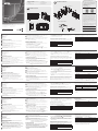
12-Key Network Remote Pad
Quick Start Guide
VPK312
Package Contents
1 VPK312 12-Key Network Remote Pad
1 Faceplate
1 Pack of Button Caps
1 Power Adapter
1 2-pole Terminal Block
1 User Instructions
A
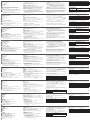
Hardware Review
B
Hardware Installation
이 기기는 업무용(A급) 전자파적합기기로서 판매자 또는 사용자는 이 점을
주의하시기 바라며, 가정외의 지역에서 사용하는 것을 목적으로 합니다.
EMC Information
FEDERAL COMMUNICATIONS COMMISSION INTERFERENCE
STATEMENT:
This equipment has been tested and found to comply with the limits
for a Class A digital device, pursuant to Part 15 of the FCC Rules.
These limits are designed to provide reasonable protection against
harmful interference when the equipment is operated in a commercial
environment. This equipment generates, uses, and can radiate radio
frequency energy and, if not installed and used in accordance with
the instruction manual, may cause harmful interference to radio
communications. Operation of this equipment in a residential area
is likely to cause harmful interference in which case the user will be
required to correct the interference at his own expense.
FCC Caution: Any changes or modifi cations not expressly approved by
the party responsible for compliance could void the user's authority to
operate this equipment.
Warning: Operation of this equipment in a residential environment
could cause radio interference.
This device complies with Part 15 of the FCC Rules. Operation is subject
to the following two conditions:(1) this device mat not cause harmful
interference, and(2) this device must accept any interference received,
including interference that may cause undesired operation.
Important. Before proceeding, download the Installation and
Operation Manual by visiting the website, www.aten.com and
navigating to the product page. The manual includes important
warnings, loading specifi cations and grounding instructions.
Achtung: Der Gebrauch dieses Geräts in Wohnumgebung kann
Funkstörungen verursachen.
S
upport and Documentation Notice
All information, documentation, fi rmware, software utilities,
and specifi cations contained in this package are subject to
change without prior notifi cation by the manufacturer.
To reduce the environmental impact of our products, ATEN
documentation and software can be found online at
http://www.aten.com/download/
Technical Support
www.aten.com/support
Scan for more information
ATEN Website User Manual
ATEN VanCryst
™
37.3 mm
96.9 mm
51.95 mm
4
1
2
3
5
4
1
2
3
5
6
Wall Box
(Not included in package)
+5V
+5V
GND
GND
5mm
1
2
3
(+)
(-)
Power Supply Information
A
Description de l’appareil
1
Bouton et voyant d’état
2
Voyant réseau
3
Bouton de réinitialisation
4
Port Ethernet
5
Courant continu
B
Installation matérielle
1
Préparez votre site d’installation et installez un boîtier mural (non fourni
dans l’emballage).
2
Installez les capuchons de bouton sur le clavier déporté.
3
Branchez l’appareil au réseau local à l’aide d’un câble Ethernet.
4
Alimentez l’appareil par l’une ou plusieurs méthodes suivantes pour garantir
une alimentation redondante.
• Branchez le clavier déporté à l’alimentation continue (CC).
• Assurez-vous que le routeur connecté prenne en charge la fonctionnalité PSE.
5
Fixez l’appareil au boîtier mural avec deux vis.
6
Montez la plaque frontale.
Informations relatives à l’alimentation
1
Coupez l’extrémité du connecteur de l’adaptateur secteur.
2
Dénudez 5 mm (0,5 cm) de gaine isolante sur le câble de l’adaptateur
secteur pour mettre à nu deux fi ls : un fi l +5 V et un fi l GND (masse).
3
Insérez le fi l +5 V et le fi l GND dénudés dans le connecteur du bornier à
2 pôles fourni.
Remarque : une des méthodes pour déterminer la polarité d’un fi l dénudé
(p. ex. : +5 V ou GND) consiste à utiliser un voltmètre.
Confi guration du logiciel
Coupler le clavier déporté à un commutateur de présentation
1. Connectez-vous à la console Web du commutateur de présentation auquel
vous voulez coupler le clavier déporté.
2. Accédez à Système > Clavier déporté, puis cliquez sur Nouveau.
3. Dans l’écran contextuel, cliquez sur l’onglet Non couplé.
4. Sélectionnez un ou plusieurs claviers déportés dans la liste, puis cliquez sur Ajouter.
Remarque : pour identifi er votre clavier déporté parmi les autres, cliquez
sur
. Les voyants de bouton de l’appareil sélectionné se
mettront à clignoter en orange et en blanc.
5. À partir du clavier déporté que vous avez ajouté, cliquez sur , puis
sélectionnez Modifi er la disposition. La console Web du clavier déporté
s’ouvre.
6. Utilisez l’onglet Boutons pour confi gurer l’attribution des boutons.
Assurez-vous que les paramètres à ce niveau correspondent à la disposition
physique.
Confi guration des paramètres réseau du clavier déporté
Vous pouvez confi gurer les paramètres réseau du clavier déporté à l’aide de
sa console Web après avoir couplé l’appareil en question au commutateur de
présentation. Connectez-vous à la console Web du clavier déporté, comme
suit :
Paramètres par défaut
Adresse IP Adresse IP dynamique ou 192.168.0.60
Nom d’utilisateur
Les identifi ants de connexion au commutateur de
présentation couplé
Mot de passe
Clavier réseau déporté 12 touches VPK312
www.aten.com
Fonctionnement
• Appuyez sur les boutons pour appliquer les fonctions. Reportez-vous au
tableau ci-après pour une description des voyants.
Voyant de bouton État
Allumé en orange La fonction est disponible.
Allumé en blanc La fonction est activée.
Allumé
progressivement
La fonction n’est pas applicable au scénario.
• Pour restaurer les paramètres réseau par défaut, retirez la plaque frontale,
puis appuyez brièvement sur le bouton Réinitialisation. Pour restaurer
les paramètres par défaut du système, appuyez et maintenez le bouton
Réinitialisation enfoncé pendant 5 s.
A
Hardwareübersicht
1
Taste und Status-LED
2
Netzwerk-LED
3
Rücksetztaste
4
Ethernet-Port
5
Gleichstrom
B
Installation der Hardware
1
Bereiten Sie Ihren Installationsort vor und installieren Sie einen
Unterputzkasten (nicht in dieser Verpackung enthalten).
2
Montieren Sie den Tastenblock auf dem Remote-Tastenfeld.
3
Schließen Sie das Gerät mit Hilfe eines Ethernet-Kabels am LAN an.
4
Versorgen Sie das Gerät mit Hilfe einer der nachstehenden Methoden
mit Strom oder benutzen Sie beide Methoden für eine redundante
Stromversorgung.
• Schließen Sie das Remote-Tastenfeld an Gleichstrom an.
• Vergewissern Sie sich, dass der verbundene Router die PSE-Funktionalität
unterstützt.
5
Schrauben Sie das Gerät mit Hilfe von 2 Schrauben am Unterputzkasten fest.
6
Montieren Sie die Blende.
Informationen zur Stromversorgung
1
Schneiden Sie das Anschlussende des Netzkabels ab.
2
Isolieren Sie 5 mm (0,5 cm) des Netzteilkabels ab, sodass zwei Drähte
freiliegen: Ein +5-V-Draht und ein Erdungsdraht.
3
Stecken Sie den freigelegten +5-V-Draht und den Erdungsdraht sicher in
den 2-poligen Anschluss am Anschlussblock.
Hinweis: Sie können die Polarität des freigelegten Drahtes (z. B. +5 V oder
Erde) beispielsweise mit einem Spannungsmesser ermitteln.
Softwarekonfi gurierung
Koppeln Sie das Remote-Tastenfeld mit einem Präsentationsswitch
1. Melden Sie sich an der Webkonsole des Präsentationsswitches an, mit dem
Sie das Remote-Tastenfeld koppeln möchten.
2. Gehen Sie zu System > Remote-Tastenfeld und klicken Sie dort auf Neu
hinzufügen.
3. Klicken Sie in dem eingeblendeten Popup-Fenster den Reiter Getrennt an.
4. Wählen Sie in der Liste ein oder mehrere Remote-Tastenfelder aus und
klicken Sie anschließend auf Hinzufügen.
Hinweis: Klicken Sie auf
, um die einzelnen Remote-Tastenfelder
identifi zieren zu können. Die Tasten-LEDs des gewählten Geräts
beginnen Orange und Weiß zu blinken.
5. Klicken Sie auf
des hinzugefügten Remote-Tastenfeldes und wählen Sie
dann Layout bearbeiten aus. Daraufhin öffnet sich die Webkonsole des
Remote-Tastenfeldes.
6. Konfi gurieren Sie mit Hilfe des Reiters Tasten die Tastenzuweisungen.
Vergewissern Sie sich, dass die Einstellungen hier dem physikalischen Layout
entsprechen.
Konfi gurieren der Netzwerkeinstellungen des Remote-Tastenfeldes
Sie können die Netzwerkeinstellungen des Remote-Tastenfeldes über seine
Webkonsole konfi gurieren, nachdem es mit einem Präsentationsswitch
gekoppelt wurde. Melden Sie sich hierfür mit den nachstehenden Daten an der
Webkonsole des Remote-Tastenfeldes an:
VPK312 – Netzwerk-Remote-Tastenfeld mit 12 Tasten
www.aten.com
Standardeinstellungen
IP-Adresse Dynamische IP-Adresse oder 192.168.0.60
Benutzername
Die Anmeldedaten des gekoppelten
Präsentationsswitches
Passwort
Bedienung
• Drücken Sie die Tasten, um die jeweiligen Funktionen anzuwenden. Sehen
Sie für Informationen zur LED-Anzeige in der nachstehenden Tabelle nach.
Tasten-LED Status
Leuchtet Orange Die Funktion kann benutzt werden.
Leuchtet Weiß Die Funktion ist aktiviert.
Schwach leuchtend
Die Funktion steht für dieses Szenario nicht zur
Verfügung.
• Wenn Sie die Standardnetzwerkeinstellungen wiederherstellen
möchten, dann entfernen Sie die Blende und drücken Sie anschließend
einmal die Taste Rücksetzen. Halten Sie zum Wiederherstellen der
Standardsystemeinstellungen die Taste Rücksetzen 5 s lang gedrückt.
A
Reseña del hardware
1
Botón y led de estado
2
Led de red
3
Botón de reinicio
4
Puerto Ethernet
5
Alimentación CC
B
Instalación del hardware
1
Prepare el sitio de instalación e instale una caja de pared (no incluida en el paquete).
2
Coloque las tapas de los botones en el panel remoto.
3
Conecte la unidad a la LAN con un cable Ethernet.
4
Suministre alimentación a la unidad realizando uno de los siguientes pasos,
o bien ambos para una alimentación redundante.
• Conecte el panel remoto a la alimentación CC.
• Asegúrese de que el enrutador conectado sea compatible con la
funcionalidad PSE.
5
Fije la unidad a la caja de pared con dos tornillos.
6
Coloque la placa frontal.
Información sobre la fuente de alimentación
1
Corte el extremo del conector del adaptador de alimentación.
2
Quite 5 mm (0,5 cm) de la cubierta aislante del cable del adaptador de
alimentación para exponer dos cables: un cable + 5 V y un cable GND (tierra).
3
Inserte fi rmemente los cables expuestos de + 5 V y GND en el conector de
bloque de terminales de 2 pines suministrado.
Nota: Un método para determinar la polaridad de un cable expuesto (es
decir, + 5 V o GND) es utilizando un voltímetro.
Confi guración del software
Emparejar el panel remoto con un conmutador de presentación
1. Inicie sesión en la consola web del conmutador de presentación con el que
desea emparejar el panel remoto.
2. Acceda a Sistema > Panel remoto y haga clic en Añadir nuevo.
3. En la pantalla emergente, haga clic en la pestaña Sin emparejar.
4. Seleccione uno o varios paneles remotos de la lista y haga clic en Añadir.
Nota: Para identifi car el panel remoto entre varios, haga clic en
.
Los ledes de los botones de la unidad seleccionada empezarán a
parpadear en naranja y blanco.
5. En el panel remoto añadido, haga clic en y seleccione Editar diseño. Se
abrirá la consola web del panel remoto.
6. Utilice la pestaña Botones para confi gurar la asignación de los botones.
Asegúrese de que esta confi guración coincida con el diseño físico.
Confi gurar los ajustes de red del panel remoto
Una vez el panel remoto esté emparejado con un conmutador de presentación,
puede confi gurar los ajustes de red del panel remoto mediante su consola
web. Inicie sesión en la consola web del panel remoto con los siguientes datos:
Ajustes predeterminados
Dirección IP Dirección IP dinámica o 192.168.0.60
Nombre de usuario
Las credenciales del conmutador de presentación
emparejado
Contraseña
Panel remoto de red VPK312 de 12 botones
www.aten.com
Funcionamiento
• Pulse los botones para aplicar las funciones. Consulte la siguiente tabla para
obtener información sobre las indicaciones de los ledes.
Led de botón Estado
Se ilumina en
naranja
La función está disponible para su uso.
Se ilumina en blanco La función ha sido habilitada.
Se atenúa
La función no es aplicable al escenario.
• Para restaurar los ajustes de red predeterminados, retire la placa frontal
y pulse una vez el botón Reinicio. Para restaurar la confi guración
predeterminada del sistema, mantenga pulsado el botón Reinicio durante 5
segundos.
A
Panoramica hardware
1
Pulsante e LED di stato
2
LED di rete
3
Pulsante reset
4
Porta Ethernet
5
Per alimentazione CC
B
Installazione hardware
1
Preparare il sito di installazione e installare un scatola a parete (non inclusa
nella confezione).
2
Installare le coperture dei pulsanti sul Pad remoto.
3
Collegare l'unità alla LAN tramite un cavo Ethernet.
4
Dotare l'unità di alimentazione ridondante applicando uno dei due metodi
seguenti.
• Collegare il Pad remoto all'alimentatore CC.
• Verifi care che il router connesso supporti la funzionalità PSE.
5
Fissare l'unità alla scatola a parete con due viti.
6
Applicare la piastra di copertura.
Informazioni sull'alimentatore
1
Tagliare l'estremità del connettore dell'adattatore di alimentazione.
2
Togliere 5 mm (0,5 cm) dell'isolamento del cavo dell'adattatore di
alimentazione per esporre due fi li: un fi lo +5 V e un fi lo di Massa (messa a
terra).
3
Inserire il cavo +5 V e il cavo Massa stabilmente nel connettore del blocco
terminale bipolare in dotazione.
Nota: Per poter determinare la polarità dei fi li esposti (ad esempio +5 V o
Massa) usare un voltmetro.
Confi gurazione Software
Abbinamento del Pad Remoto con uno Switch per presentazioni
1. Accedere alla console web dello Switch per presentazioni da abbinare al Pad
Remoto.
2. Accedere a Sistema > Pad Remoto e fare clic su Aggiungi nuovo.
3. Nello schermo a comparsa, fare clic sulla scheda Non abbinati.
4. Selezionare uno o più Pad Remoti in elenco e fare clic su Aggiungi.
Nota: Per selezionare un Pad remoto tra gli altri, fare clic su
. I LED dei pulsanti
dell'unità selezionata iniziano a lampeggiare in arancione e bianco.
5. Sul Pad Remoto aggiunto, fare clic su e selezionare Modifi ca Layout. Si
apre la console web del Pad remoto.
6. Usare la scheda Pulsanti per defi nire l'assegnazione dei pulsanti. Verifi care
che le impostazioni scelte coincidano con il layout fi sico.
Impostazioni di Rete del Pad Remoto
Dopo l'abbinamento a uno switch per presentazioni, è possibile confi gurare
le impostazioni di rete del Pad remoto dalla sua console web. Accedere alla
console web del Pad remoto nel modo seguente:
Impostazioni predefi nite
Indirizzo IP Indirizzo IP Dinamico o 192.168.0.60
Nome utente
Credenziali dello switch per presentazioni abbinato
Password
Pad Remoto di rete a 12 tasti VPK312
www.aten.com
Funzionamento
• Premere i pulsanti per applicare le funzioni. Consultare la tabella seguente
per informazioni sugli indicatori LED.
LED Pulsante Stato
Lampeggia in
arancione
Funzione pronta all'uso.
Lampeggia in bianco Funzione abilitata.
Illuminazione ridotta
Funzione non applicabile a questo scenario.
• Per ripristinare le impostazioni di rete predefi nite, rimuovere la piastra di
copertura e premere una volta il tasto Reset; per ripristinare le impostazioni
predefi nite di sistema, tenere premuto il pulsante Reset per 5 secondi.
A
Обзор оборудования
1
Кнопка и индикатор состояния
2
Индикатор сети
3
Кнопка сброса
4
Порт Ethernet
5
Питание постоянного тока
B
Подготовка к работе
1
Подготовьте место монтажа и установите настенный короб (не
входит в комплект).
2
Установите нажимные элементы кнопок на панель ДУ.
3
Подключите устройство к локальной сети с помощью кабеля Ethernet.
4
Подключите устройство к источнику питания, выполнив одно или оба
из указанных действий для обеспечения резервного питания.
•
Подключите панель ДУ к источнику пост. тока.
•
Убедитесь, что маршрутизатор является питающим устройством PoE.
5
Прикрепите устройство к настенному коробу двумя винтами.
6
Прикрепите лицевую панель.
Сведения об источнике питания
1
Срежьте концевую часть адаптера питания.
2
Удалите изоляцию на кабеле адаптера питания на расстоянии 5 мм
(0,5 см), чтобы показались два провода: провод +5 В и заземляющий
провод.
3
Плотно вставьте оголенный провод +5 В и провод заземления в
имеющуюся 2-полюсную клеммную коробку.
Примечание. Один из способов определения полярности оголенных
проводов (отличия провода +5 В от заземляющего
провода) — использование вольтметра.
Конфигурация ПО
Сопряжение панели ДУ с презентационным коммутатором
1. Войдите в веб-консоль презентационного коммутатора, с которым вы
хотите выполнить сопряжение панели ДУ.
2. Перейдите в меню Система > Панель ДУ и нажмите Добавить новое.
3. Во всплывающем экране нажмите на вкладку Не сопряжено.
4. Выберите в списке одну или несколько панелей ДУ и нажмите
Добавить.
Примечание. Чтобы идентифицировать панель ДУ среди других
устройств, нажмите
. Индикаторы кнопок выбранного
устройства начнут мигать оранжевым и белым цветом.
5. Из добавленной панели ДУ нажмите
и выберите Редактировать
схему. Откроется веб-консоль панели ДУ.
6. Используйте вкладку Кнопки для конфигурирования назначения
кнопок. Убедитесь, что настройки в меню соответствуют фактической
схеме устройства.
Конфигурирование сетевых настроек панели ДУ
Сетевые настройки панели ДУ можно выполнить через веб-консоль после
сопряжения с презентационным коммутатором. Войдите в веб-консоль
панели ДУ с использованием следующих данных:
Настройки по умолчанию
IP-адрес Динамический IP-адрес или 192.168.0.60
Имя пользователя
Учетные данные сопряженного
презентационного коммутатора
Пароль
12-клавишная сетевая панель дистанционного управления VPK312
www.aten.com
Эксплуатация
•
Нажмите на кнопки для применения функций. Сведения о
светодиодных индикаторах см. в таблице ниже.
Индикатор кнопки Состояние
Горит оранжевым цветом Функция доступна для использования.
Горит белым цветом Функция активирована.
Не горит
Функция неприменима для данного
сценария.
•
Чтобы вернуться к сетевым настройкам по умолчанию, снимите
лицевую панель и нажмите один раз на кнопку Сброс; чтобы
вернуться к системным настройкам по умолчанию, нажмите и
удерживайте кнопку Сброс в течение 5 секунд.
A
Hardware Review
1
Button & Status LED
2
Network LED
3
Reset Button
4
Ethernet Port
5
DC Power
B
Hardware Installation
1
Prepare your installation site and install a wall box (not included in the
package).
2
Install button caps to the Remote Pad.
3
Connect the unit to LAN using an Ethernet cable.
4
Supply the unit with power by doing one, or both of the following to
provide redundant power.
• Connect the Remote Pad to DC power.
• Make sure the connected router supports the PSE functionality.
5
Secure the unit to the wall box with two screws
6
Attach the faceplate.
Power Supply Information
1
Cut the connector end of the power adapter.
2
Strip 5 mm (0.5 cm) off the insulation cover of the Power Adapter cable to
expose two wires: a +5V wire and a GND (grounding) wire.
3
Insert the exposed +5V wire and GND wire tightly into the provided 2-pole
Terminal Block Connector.
Note: One method to determine an exposed wire’s polarity (i.e., +5V or
GND) is by using a voltmeter.
Software Confi guration
Pairing the Remote Pad with a Presentation Switch
1. Log in the web console of the Presentation Switch with which you want to
pair the Remote Pad.
2. Go to System > Remote Pad and click Add New.
3. In the pop-up screen, click the Unpaired tab.
4. Select one or multiple Remote Pads in the list and click Add.
Note: To identify the Remote Pad among others, click
. The button LEDs
on the selected unit start to blink orange and white.
5. From the added Remote Pad, click
and select Edit Layout. The web
console of the Remote Pad opens.
6. Use the Buttons tab to confi gure the button assignment. Make sure the
settings here match the physical layout.
Confi guring the Remote Pad’s Network Settings
You can confi gure the Remote Pad’s network settings via its web console after
it is paired with a Presentation Switch. Log in the Remote Pad’s web console
using the following:
Default Settings
IP Address Dynamic IP address or 192.168.0.60
Username
The credentials of the paired Presentation Switch
Password
VPK312 12-Key Network Remote Pad
www.aten.com
Operation
• Press the buttons to apply the functions. Refer to the table below for
information on LED indication.
Button LED Status
Lights orange The function is available for use.
Lights white The function has been enabled.
Dims The function is not applicable for the scenario.
• To restore default network settings, remove the faceplate and press the
Reset button once; to restore default system settings, press and hold the
Reset button for 5 seconds.
La pagina sta caricando ...
-
 1
1
-
 2
2


in altre lingue
- English: ATEN VPK312 Quick start guide
- français: ATEN VPK312 Guide de démarrage rapide
- español: ATEN VPK312 Guía de inicio rápido
- Deutsch: ATEN VPK312 Schnellstartanleitung
- русский: ATEN VPK312 Инструкция по началу работы
- português: ATEN VPK312 Guia rápido
- polski: ATEN VPK312 Skrócona instrukcja obsługi
- 日本語: ATEN VPK312 クイックスタートガイド
- Türkçe: ATEN VPK312 Hızlı başlangıç Kılavuzu
- română: ATEN VPK312 Ghid de inițiere rapidă