
© Copyright 2019 ATEN
®
International Co., Ltd.
ATEN and the ATEN logo are trademarks of ATEN International Co., Ltd. All rights reserved.
All other trademarks are the property of their respective owners.
Part No. PAPE-1223-S80G Printing Date: 10/2019
32 x 32 Modular Matrix Switch Gen. 2
Quick Start Guide
VM3250
ATEN VanCryst
™
B
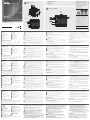
Front View
Rear View
Hardware Installation
Package Contents
1 VM3250 32 x 32 Modular Matrix Switch
1 Power Module
1 Terminal Block Connector
1 Power Cord
1 User Instructions
8
2
4
8
9
10
1
3
5
6
7
7
8 9
1
2
3
4
5
6
4
5
2
3
1
12
6
8
9
10
7
A
Hardware Review
Support and Documentation Notice
All information, documentation, fi rmware, software
utilities, and specifi cations contained in this package
are subject to change without prior notifi cation by the
manufacturer.
To reduce the environmental impact of our products,
ATEN documentation and software can be found
online at http://www.aten.com/download/
Technical Support
www.aten.com/support
이 기기는 업무용(A급) 전자파적합기기로서 판매자 또는 사용자는 이 점을
주의하시기 바라며, 가정외의 지역에서 사용하는 것을 목적으로 합니다.
EMC Information
FEDERAL COMMUNICATIONS COMMISSION INTERFERENCE
STATEMENT:
This equipment has been tested and found to comply with the limits
for a Class A digital device, pursuant to Part 15 of the FCC Rules.
These limits are designed to provide reasonable protection against
harmful interference when the equipment is operated in a commercial
environment. This equipment generates, uses, and can radiate radio
frequency energy and, if not installed and used in accordance with
the instruction manual, may cause harmful interference to radio
communications. Operation of this equipment in a residential area
is likely to cause harmful interference in which case the user will be
required to correct the interference at his own expense.
FCC Caution: Any changes or modifi cations not expressly approved by
the party responsible for compliance could void the user's authority to
operate this equipment.
Warning: Operation of this equipment in a residential environment
could cause radio interference.
Suggestion: Shielded twisted pair (STP) cables must be used with the
unit to ensure compliance with FCC & CE standards.
This device complies with Part 15 of the FCC Rules. Operation is subject
to the following two conditions:(1) this device mat not cause harmful
interference, and(2) this device must accept any interference received,
including interference that may cause undesired operation.
Important. Before proceeding, download the Installation and
Operation Manual by visiting the website, www.aten.com and
navigating to the product page. The manual includes important
warnings, loading specifi cations and grounding instructions.
Scan for more information
ATEN Website
Commutateur matriciel modulaire 32 x 32 VM3250 Gen 2
www.aten.com
A
Vue d’ensemble
Vue de face
1
Affi chage LCD
2
Boutons-poussoirs de fonction
3
Boutons-poussoirs d’entrée (1-32)
4
Boutons-poussoirs de sortie (1-32)
5
LED d’alarme
6
LED d’alimentation redondante
7
LED d’alimentation primaire
8
Poignées
9
Poignées encastrées
10
Sangle pour câble
Vue de dos
1
Interrupteur
2
Port série RS-485/RS-422
3
Port Ethernet
4
Port série RS-232
5
Alimentation primaire
6
Fente d’alimentation redondante
7
Prise terre
8
Fentes de carte de sortie
9
Fentes de carte d’entrée
B
Installation matérielle
Reportez-vous au schéma d’installation et suivez les étapes ci-dessous pour installer
le VM3250 en toute sécurité.
1
Utilisez un fil de mise à la terre pour raccorder l’appareil à la terre en reliant une
extrémité du fi l à la borne de terre et l’autre extrémité à un objet adapté mis à la terre.
1
2
Installez des cartes d’entrée et de sortie sur le VM3250.
2
a
Retirez les vis du capot de la carte d’entrée/sortie que vous souhaitez installer,
puis retirez le capot.
b
Faites glisser la carte d’entrée/sortie dans la fente et serrez les vis sur la carte.
c
Répétez les étapes 2a à 2c pour installer toutes les cartes E/S.
3
Connectez votre appareil/vos appareils source A/V aux ports vidéo et audio des
cartes d’entrée que vous avez installées.
4
Connectez votre appareil/vos appareils d’affi chage vidéo au(x) port(s) vidéo des
cartes de sortie que vous avez installées.
5
(Facultatif) Connectez vos enceintes/appareils de restitution audio au(x) port(s)
audio des cartes de sortie que vous avez installées.
6
(Facultatif) Pour contrôler plusieurs VM3250 via une communication série,
utilisez un câble série approprié pour relier un ordinateur ou un contrôleur série
au port série RS-485/RS-422 femelle du VM3250. Utilisez le connecteur de
bornier fourni pour cette connexion.
7
(Facultatif) Pour utiliser le VM3250 à distance via l’interface Web, connectez le
port Ethernet du VM3250 au réseau à l’aide d’un câble Ethernet.
8
(Facultatif) Pour contrôler le VM3250 via une communication série, utilisez un
câble série approprié pour relier un ordinateur ou un contrôleur série au port
série RS-232 femelle du VM3250.
9
Branchez le cordon d’alimentation fourni sur la prise secteur principale du
VM3250, puis sur une source d’alimentation.
10
(Facultatif) Pour une alimentation redondante, branchez un module
d’alimentation secondaire au connecteur d’alimentation redondant.
3
11
Faites la mise à la terre tous les appareils connectés de votre installation.
12
Allumez le VM3250 et tous les appareils de l’installation.
Remarque :
1. N’ignorez pas cette étape. Une mise à la terre appropriée aide à éviter que l’appareil ne
soit endommagé par des surtensions ou de l’électricité statique.
2. Reportez-vous au manuel d’utilisation pour plus de détails.
3. Achetez un module d’alimentation secondaire pour la redondance de l’alimentation.
C
Fonctionnement
Le VM3250 peut être géré localement via les boutons-poussoirs du panneau avant
et à distance via sa console Web ou un contrôleur/ordinateur série à travers une
communication série RS-232/RS-422/RS-485.
Boutons-poussoirs du panneau avant
• Pour accéder aux paramètres du système via le panneau avant, entrez le mot de
passe par défaut 1234 à l’aide de boutons-poussoirs numériques.
• Pour confi gurer l’affectation d’une entrée A/V à des sorties :
1. Appuyez sur le bouton-poussoir Entrée de l’entrée que vous souhaitez confi gurer.
Les boutons-poussoirs Sortie des sorties affectées à cette entrée s’allument.
2. Pour affecter l’entrée à une sortie, appuyez sur le bouton-poussoir Sortie de
la sortie correspondante. Le bouton-poussoir Sortie s’allume pour indiquer que
la confi guration a réussi.
3. Pour annuler l’affectation à une sortie, appuyez sur le bouton-poussoir Sortie
de la sortie correspondante. Le bouton-poussoir Sortie diminue d’intensité pour
indiquer qu’il n’est pas affecté à l’entrée.
Remarque : Par défaut, les signaux audio et vidéo d’une entrée sont commutés au
lieu d’être indépendants.
Pour confi gurer les sources audio et vidéo
indépendamment, utilisez les
boutons-poussoirs Audio
et
Video.
• Pour accéder aux paramètres du système, appuyez sur le bouton-poussoir Menu.
Interface Web
L’interface Web permet d’accéder aux paramètres système avancés, tels que les
planifi cations de profi l et les comptes d’utilisateur. Le VM3250 prend en charge
jusqu’à 16 connexions simultanées. Utilisez les informations suivantes pour accéder
à l’interface Web pour la première fois.
• Adresse IP par défaut : 192.168.0.60
• Nom d’utilisateur/mot de passe par défaut : administrator/password
VM3250 Modularer 32-x-32-Matrixswitch der 2. Generation
www.aten.com
A
Übersicht
Ansicht von vorn
1
LCD-Display
2
Funktionstasten
3
Eingangstasten (1 – 32)
4
Ausgangstasten (1 – 32)
5
Alarm-LED
6
LED redundante Spannungsversorgung
7
LED primäre Spannungsversorgung
8
Tragegriffe
9
Eingelassene Tragegriffe
10
Kabelbinder
Ansicht von hinten
1
Netzschalter
2
Serieller RS-422/485-Port
3
Ethernet-Port
4
Serieller RS-232-Port
5
Primäre Spannungsversorgung
6
Steckplatz für redundante
Spannungsversorgung
7
Erdungsklemme
8
Ausgangsplatinensteckplätze
9
Eingangsplatinensteckplätze
B
Installation der Hardware
Bitte sehen Sie für einen sicheren Anschluss des VM3250 in der Abbildung zum
Anschluss nach und folgen Sie nachstehenden Schritten.
1
Erden Sie das Gerät mit Hilfe einer Erdungsleitung, indem Sie das eine Ende der
Erdungsleitung an der Erdungsklemme anschließen und das andere Ende mit
einem geeigneten geerdeten Gegenstand verbinden.
1
2
Bauen Sie die Eingangs- und Ausgangsplatinen in den VM3250 ein.
2
a
Drehen Sie die Schrauben der Abdeckung der Eingangs- und
Ausgangssteckplätze heraus, in die Sie Eingangs- bzw. Ausgangsplatinen
einbauen möchten und entfernen Sie anschließend die Abdeckung.
b
Stecken Sie die Eingangs- bzw. Ausgangsplatine in den jeweiligen Steckplatz
und fi xieren Sie sie mit Hilfe der Schraube.
c
Wiederholen Sie die Schritte 2a bis 2c, um alle Ein- und Ausgangsplatinen
einzubauen.
3
Schließen Sie Ihr/-e Audio- und Videoquellgerät/-e am/an den Audio- und
Videoport/-s der eingebauten Eingangsplatinen an.
4
Schließen Sie Ihr/-e Videoanzeigegerät/-e am/an den Videoport/-s der
eingebauten Ausgangsplatinen an.
5
(Optional) Schließen Sie Ihre Lautsprecher bzw. Ihr/-e Audiowiedergabegerät/-e
am/an den Audioport/-s der eingebauten Ausgangsplatinen an.
6
(Optional) Wenn Sie mehrere VM3250-Einheiten über die serielle Schnittstelle
steuern möchten, dann benutzen Sie ein geeignetes serielles Kabel, um einen
Computer oder einen seriellen Controller am weiblichen seriellen RS-422/485-Port
des VM3250 anzuschließen. Benutzen Sie für diese Verbindung die mitgelieferte
Klemmenleiste.
7
(Optional) Wenn Sie das VM3250 remote über die Web-Schnittstelle steuern
möchten, dann schließen Sie für die Netzwerkverbindung am Ethernet-Port des
VM3250 ein Ethernet-Kabel an.
8
(Optional) Wenn Sie das VM3250 über die serielle Schnittstelle steuern möchten,
dann benutzen Sie ein geeignetes serielles Kabel, um einen Computer oder einen
seriellen Controller am weiblichen seriellen RS-232-Port des VM3250 anzuschließen.
9
Stecken Sie den Kaltgerätestecker des mitgelieferten Netzkabels in die Buchse
für die primäre Spannungsversorgung des VM3250 und anschließend den
Netzstecker in eine Netzsteckdose.
10
(Optional) Stecken Sie für eine redundante Spannungsversorgung ein
sekundäres Spannungsversorgungsmodul in den Steckplatz für die redundante
Spannungsversorgung.
3
11
Erden Sie alle mit dem VM3250 verbundenen Geräte.
12
Schalten Sie den VM3250 und alle an ihm angeschlossenen Geräte ein.
Hinweis:
1. Überspringen Sie diesen Schritt nicht. Eine ordnungsgemäße Erdung hilft dabei,
Schäden am Gerät durch Überspannung oder elektrostatische Aufl adung vorzubeugen.
2. Schlagen Sie für alle Einzelheiten hierzu im Benutzerhandbuch nach.
3. Das sekundäre Spannungsversorgungsmodul für die redundante Spannungsversorgung
ist als Zubehör erhältlich.
C
Bedienung
Der VM3250 kann vor Ort über die Tasten der Bedienleiste und remote über seine
Web-Schnittstelle oder einen seriellen Controller bzw. über einen am seriellen
RS-232-/RS-422/485-Port angeschlossenen Computer gesteuert werden.
Bedienfeldtasten
• Damit Sie über das Bedienfeld auf die Systemeinstellungen zugreifen können,
müssen Sie mit Hilfe der Zifferntasten das Standardpasswort 1234 eingeben.
• Konfi guration der Zuweisung eines Audio-/Videoeingangs an Ausgänge:
1. Drücken Sie die Eingangstasten des Eingangs, den Sie konfi gurieren möchten.
Daraufhin leuchten die Ausgangstasten, die diesem Eingang zugewiesen sind.
2. Drücken Sie nun die Ausgangstasten, deren Ausgang Sie dem Eingang
zuweisen möchten. Daraufhin leuchtet die Ausgangstasten, um Ihnen
anzuzeigen, dass die Konfi guration erfolgreich war.
3. Drücken Sie die Ausgangstaste des jeweiligen Ausgangs, wenn Sie die
Zuweisung zu dem jeweiligen Ausgang aufheben möchten. Daraufhin wird
diese Ausgangstasten abgedunkelt, um Ihnen anzuzeigen, dass sie diesem
Eingang nicht mehr zugewiesen ist.
Hinweis: Standardmäßig werden die Audio- und Videosignale eines Eingangs zusammen
geschaltet und nicht getrennt voneinander.
Wenn Sie konfi gurieren möchten,
dass die Audio- und Videoquellen unabhängig voneinander geschaltet
werden, dann benutzen Sie die
Audio-
und
Video-Tasten.
• Wenn Sie auf die Systemeinstellungen zugreifen möchten, dann drücken Sie die
Menu-Taste.
Webschnittstelle
Die Webschnittstelle gewährt Ihnen den Zugriff auf erweiterte Systemeinstellungen
wie beispielsweise Profi l-Zeitpläne und Benutzerkonten. Der VM3250 unterstützt bis
zu 16 gleichzeitige Anmeldungen. Benutzen Sie für den erstmaligen Zugriff auf die
Webschnittstelle die nachstehenden Informationen.
• Standard-IP-Adresse: 192.168.0.60
• Standardbenutzername/Standardpasswort: administrator/password
Conmutador de matriz modular 32 x 32 VM3250 Gen. 2
www.aten.com
A
Información general
Vista frontal
1
Pantalla LCD
2
Botones de comando de función
3
Botones de comando de entrada (1-32)
4
Botones de comando de salida (1-32)
5
Led de alarma
6
Led de alimentación redundante
7
Led de alimentación primaria
8
Asas
9
Asas empotradas
10
Correa del cable
Vista posterior
1
Interruptor de alimentación
2
Puerto serie RS-485/RS-422
3
Puerto Ethernet
4
Puerto serie RS-232
5
Fuente de alimentación primaria
6
Ranura de alimentación redundante
7
Toma de tierra
8
Ranuras de placa de salida
9
Ranuras de placa de entrada
B
Instalación del hardware
Consulte el diagrama de instalación y siga los siguientes pasos para instalar con
seguridad el VM3250.
1
Utilice un cable de toma de tierra para establecer la conexión a tierra de la
unidad, conectando un extremo del cable al terminal de toma de tierra y el otro
extremo del cable a un objeto adecuadamente conectado a tierra.
1
2
Instale las placas de entrada y salida en el VM3250.
2
a
Desatornille la cubierta de la placa de entrada/salida que desee instalar y,
a continuación, retire la cubierta.
b
Inserte la placa de entrada/salida en la ranura y apriete los tornillos de la placa.
c
Repita los pasos 2a a 2c para instalar todas las placas de E/S.
3
Conecte sus dispositivos de fuente A/V a los puertos de vídeo y audio de las
placas de entrada que haya instalado.
4
Conecte sus dispositivos de visualización de vídeo a los puertos de vídeo de las
placas de salida que haya instalado.
5
(Opcional) Conecte sus altavoces/dispositivos de salida de audio a los puertos de
audio de las placas de salida que haya instalado.
6
(Opcional) Si utiliza la comunicación en serie para controlar varias unidades
VM3250, utilice un cable serie apropiado para conectar un ordenador o un
controlador serie al puerto serie hembra RS-485/RS-422 del VM3250. Utilice el
conector de bloque terminal suministrado para esta conexión.
7
(Opcional) Si utiliza remotamente el VM3250 a través de la interfaz web, conecte
un cable Ethernet desde la red al puerto Ethernet del VM3250.
8
(Opcional) Si utiliza la comunicación en serie para controlar el VM3250, utilice
un cable serie apropiado para conectar un ordenador o un conector serie al
puerto serie hembra RS-232 del VM3250.
9
Conecte el cable de alimentación suministrado en la entrada de alimentación
primaria del VM3250 y luego conéctelo a una fuente de alimentación.
10
(Opcional) Para la alimentación redundante, conecte un módulo de alimentación
secundaria en la ranura de alimentación redundante.
3
11
Conecte a tierra todos los dispositivos conectados de su instalación.
12
Encienda el VM3250 y todos los dispositivos de la instalación.
Nota:
1. No omita este paso. Una conexión a tierra apropiada evita que se dañe la unidad
debido a sobrecargas eléctricas o electricidad estática.
2. Consulte el manual de usuario para obtener más detalles.
3. Adquiera un módulo de alimentación secundaria para la alimentación redundante.
C
Funcionamiento
Puede utilizar el VM3250 de forma local a través de los botones de comando
del panel frontal y de forma remota mediante su consola web o un controlador
serie/ordenador con la comunicación en serie RS-232/RS-422/RS-485.
Botones de comando del panel frontal
• Para acceder a la confi guración del sistema a través del panel frontal, introduzca
la contraseña predeterminada 1234 con los botones de comando numéricos.
• Para confi gurar la asignación de una entrada A/V a las salidas:
1. Pulse el botón de comando de entrada de la entrada que desee confi gurar.
Los botones de comando de salida de las salidas que se han asignado con la
luz de esta entrada encendida.
2. Para asignar la entrada a una salida, pulse el botón de comando de salida
de la salida correspondiente. El botón de comando de salida se enciende para
indicar que la confi guración se ha realizado correctamente.
3. Para cancelar la asignación a una salida, pulse el botón de comando de salida
de la salida correspondiente. El botón de comando de salida se atenúa para
indicar que no está asignado a la entrada.
Nota: Por defecto, las señales de audio y vídeo de una entrada se conmutan juntas en
lugar de ser independientes.
Para confi gurar las fuentes de audio y vídeo de
manera independiente, utilice los
botones de comando Audio
y
Video.
• Para acceder a la confi guración del sistema, pulse el botón de comando Menu.
Interfaz web
La interfaz web proporciona acceso a la confi guración avanzada del sistema, como
programaciones de perfi l y cuentas de usuario. Pueden iniciar sesión en el VM3250
hasta 16 usuarios a la vez. Utilice la información siguiente para acceder a la interfaz
web por primera vez.
• Dirección IP predeterminada: 192.168.0.60
• Nombre de usuario/contraseña predeterminados: administrator/password
Matrice modulare 32 x 32 VM3250 Gen. 2
www.aten.com
A
Panoramica
Vista anteriore
1
Display LCD
2
Pulsanti funzione
3
Pulsanti di ingresso (1-32)
4
Pulsanti di uscita (1-32)
5
LED di allarme
6
LED di alimentazione ridondante
7
LED di alimentazione principale
8
Impugnature
9
Impugnature incassate
10
Fascetta per cavi
Vista posteriore
1
Interruttore di alimentazione
2
Porta seriale RS-485 / RS-422
3
Porta Ethernet
4
Porta seriale RS-232
5
Alimentazione principale
6
Slot di alimentazione ridondante
7
Terminale di messa a terra
8
Slot schede di uscita
9
Slot schede di ingresso
B
Installazione hardware
Facendo riferimento allo schema di installazione e applicando la procedura seguente,
è possibile installare in tutta sicurezza l'unità VM3250.
1
Usando un apposito cavo, effettuare la messa a terra dell'unità, collegando
un'estremità del cavo al terminale di messa a terra e l'altra a un oggetto
adeguatamente collegato al suolo.
1
2
Installare le schede di ingresso e uscita sull'unità VM3250.
2
a
Rimuovere le viti del coperchio della scheda di ingresso/uscita da installare,
quindi rimuovere il coperchio.
b
Far scorrere la scheda di ingresso/uscita nel relativo slot e stringere le viti di
fi ssaggio sulla scheda.
c
Ripetere i passi da 2a a 2c per installare tutte le schede I/O.
3
Collegare i dispositivi sorgente A/V alle porte Video e Audio delle schede di
ingresso installate.
4
Collegare i dispositivi di visualizzazione alle porte Video delle schede di uscita
installate.
5
(Opzionale) Collegare gli altoparlanti o i dispositivi di uscita audio alle porte
Audio delle schede di uscita installate.
6
(Opzionale) Per controllare più unità VM3250 tramite comunicazione seriale,
è possibile servirsi di un opportuno cavo seriale per collegare un computer
o un controller seriale all'uscita femmina della porta seriale RS-485 / RS-422
sull'unità VM3250. Per realizzare questa connessione, servirsi del connettore di
morsettiera in dotazione.
7
(Opzionale) Per il controllo remoto dell'unità VM3250 tramite interfaccia web,
collegare la porta Ethernet dell'unità alla rete tramite un cavo Ethernet.
8
(Opzionale) Per controllare l'unità VM3250 tramite comunicazione seriale, è
possibile servirsi di un opportuno cavo seriale per collegare un computer o
un controller seriale all'uscita femmina della porta seriale RS-232 sull'unità
VM3250.
9
Inserire il cavo di alimentazione in dotazione nella presa di alimentazione
principale dell'unità VM3250 e quindi a una sorgente elettrica.
10
(Opzionale) Per attivare l'alimentazione ridondante, inserire un alimentatore
secondario nello slot di alimentazione ridondante.
3
11
Effettuare la messa a terra di tutti i dispositivi collegati all'impianto.
12
Accendere l'unità VM3250 e tutti i dispositivi dell'impianto.
Nota:
1. eseguire sempre questo passo. Un'adeguata messa a terra permette di evitare danni
all'unità dovuti a sovratensioni o elettricità statica.
2. Per ulteriori dettagli, consultare il manuale d'uso.
3. Per garantire l'alimentazione ridondante, acquistare un alimentatore secondario.
C
Funzionamento
L'unità VM3250 può essere controllata localmente tramite i pulsanti nel pannello
anteriore, oppure da remoto, tramite la sua console web o un controller/computer
seriale che utilizza i canali di comunicazione seriale RS-232/RS-422/RS-485.
Pulsanti del pannello anteriore
• Per accedere alle impostazioni di sistema tramite il pannello anteriore, occorre
inserire la password predefi nita 1234, usando i tasti numerici.
• Per defi nire l'assegnazione degli ingressi A/V alle uscite:
1. Premere il pulsante dell'ingresso che si intende confi gurare. I pulsante
dell'uscita assegnate all'ingresso selezionato si accendono.
2. Per assegnare un ingresso a un'uscita, premere il pulsante dell'uscita
corrispondente. Il pulsante dell'uscita si illumina per indicare che la
confi gurazione è andata a buon fi ne.
3. Per rimuovere l'assegnazione di un'uscita, premere il pulsante dell'uscita
corrispondente. Il pulsante dell'uscita in questione si spegne per indicare che
non è più assegnato all'ingresso.
Nota: Per impostazione predefi nita, i segnali audio e video di un ingresso sono commutati
simultaneamente e non in modo indipendente.
Per confi gurare una gestione
indipendente delle sorgenti audio e video, servirsi dei
pulsanti Audio
e
Video.
• Per accedere alla impostazioni di sistema, premere il pulsante Menu.
Interfaccia web
L'interfaccia web permette di accedere alle impostazioni avanzate di sistema, come
la defi nizione di profi li e account utente. L'unità VM3250 supporta fi no a 16 accessi
contemporanei. Per il primo accesso all'interfaccia web, usare le informazioni
seguenti.
• Indirizzo IP predefi nito: 192.168.0.60
• Nome utente/Password predefi niti: administrator/password
Модульный матричный коммутатор 2-го поколения VM3250 32 x 32
www.aten.com
A
Обзор
Вид спереди
1
ЖК-дисплей
2
Функциональные кнопки
3
Кнопки ввода (1-32)
4
Кнопки вывода (1-32)
5
Аварийный индикатор
6
Индикатор резервного источника
питания
7
Индикатор основного источника
питания
8
Ручки
9
Утопленные ручки
10
Кабельные стяжки
Вид сзади
1
Переключатель питания
2
Последовательный порт RS-485 /
RS-422
3
Порт Ethernet
4
Последовательный порт RS-232
5
Основной источник питания
6
Разъем резервного источника
питания
7
Клемма заземления
8
Разъемы плат вывода
9
Разъемы плат ввода
B
Установка оборудования
Чтобы безопасно установить устройство VM3250, следуйте схеме установки
и указанным ниже инструкциям.
1
Выполните заземление устройства, соединив один конец заземляющего
провода с клеммой заземления, а другой конец — с подходящим
заземляющим предметом.
1
2
Установите платы ввода и вывода на устройство VM3250.
2
a
Снимите винты с крышки платы ввода/вывода, которую нужно
установить, затем снимите крышку.
b
Вставьте плату ввода/вывода в разъем и затяните винты на плате.
c
Повторите шаги 2a – 2c для установки всех плат ввода/вывода.
3
Подключите источники аудио или видеосигнала к портам аудио и видео
на установленных платах ввода.
4
Подключите устройства отображения видео к видеопортам на
установленных платах вывода.
5
(Опционально) Подключите динамики / устройства вывода звука к
аудиопортам на установленных платах вывода.
6
(Опционально) Если для управления несколькими устройствами VM3250
используется последовательное соединение, подключите соответствующий
последовательный кабель к компьютеру или последовательному контроллеру
и к гнезду последовательного порта RS-485 / RS-422 на устройстве VM3250.
Используйте для этого имеющийся разъем клеммной колодки.
7
(Опционально) При использовании функции дистанционного управления
устройством VM3250 с помощью веб-интерфейса подключите сетевой
кабель Ethernet к порту Ethernet на VM3250.
8
(Опционально) Если для управления устройством VM3250 используется
последовательное соединение, подключите соответствующий
последовательный кабель к компьютеру или последовательному контроллеру
и к гнезду последовательного порта RS-232 на устройстве VM3250.
9
Подключите шнур питания к разъему основного источника питания на
VM3250 и затем к источнику питания.
10
(Опционально) Для подачи резервного питания подключите дополнительный
модуль питания к разъему резервного источника питания.
3
11
Заземлите все подключенные к системе устройства.
12
Включите питание VM3250 и всех устройств системы.
Примечание:
1. Не пропускайте этот шаг. Надлежащее заземление помогает защитить
устройство от перепадов напряжения и статического электричества.
2. Подробнее см. в руководстве пользователя.
3. При необходимости приобретите резервный модуль питания.
C
Эксплуатация
Устройством VM3250 можно управлять локально с помощью кнопок
на передней панели и дистанционно посредством веб-консоли или
последовательного контроллера/компьютера через последовательное
соединение RS-232/RS-422/RS-485.
Кнопки на передней панели
• Для доступа к системных настройкам через переднюю панель введите
пароль по умолчанию 1234 с помощью цифровых кнопок.
• Порядок настройки привязки вводов аудио/видео к выводам:
1. Нажмите кнопку Ввод, соответствующую входу, который нужно
настроить. Загорятся индикаторы кнопок Вывод, которые
соответствуют выходам, назначенным этому входу.
2. Чтобы назначить вход для конкретного выхода, нажмите кнопку
Вывод соответствующего выхода. Индикатор кнопки Вывод загорится,
оповещая об успешном изменении конфигурации.
3. Чтобы отменить привязку к выводу, нажмите на кнопку «Вывод» для
соответствующего вывода. Индикатор на кнопке Вывод погаснет,
обозначая отмену назначения входа.
Примечание: По умолчанию аудио и видеосигналы ввода переключаются вместе,
а не по отдельности.
Чтобы отдельно настроить источники аудио
и видео, используйте
кнопки Audio
и
Video.
• Для перехода к системных настройкам нажмите на кнопку Menu.
Веб-интерфейс
Веб-интерфейс предоставляет доступ к расширенным системным
настройкам, (например, к расписаниям профилей и учетным записям
пользователей). Устройство VM3250 поддерживает одновременное
подключение до 16 пользователей. Используйте следующие данные для
первого доступа к веб-интерфейсу.
• IP-адрес по умолчанию: 192.168.0.60
• Имя пользователя / пароль по умолчанию: administrator/password
VM3250 32 x 32 Modular Matrix Switch Gen. 2
www.aten.com
A
Overview
Front View
1
LCD Display
2
Function Pushbuttons
3
Input Pushbuttons (1-32)
4
Output Pushbuttons (1-32)
5
Alarm LED
6
Redundant Power LED
7
Primary Power LED
8
Handles
9
Recessed Handles
10
Cable Strap
Rear View
1
Power Switch
2
RS-485 / RS-422 Serial Port
3
Ethernet Port
4
RS-232 Serial Port
5
Primary Power Supply
6
Redundant Power Slot
7
Grounding Terminal
8
Output Board Slots
9
Input Board slots
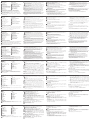
B
Hardware Installation
Refer to the installation diagram and follow the steps below to safely install the
VM3250.
1
Use a grounding wire to ground the unit by connecting one end of the wire to
the grounding terminal, and the other end to a suitable grounded object.
1
2
Install input and output boards to the VM3250.
2
a
Remove the screws on the cover of the input/output board you wish to
install, and then remove the cover.
b
Slide the input/output board into the slot and tighten the screws on the
board.
c
Repeat steps 2a to 2c to install all I/O boards.
3
Connect your A/V source device(s) to the Video and Audio port(s) of the input
boards you installed.
4
Connect your video display device(s) to the Video port(s) of the output boards
you installed.
5
(Optional) Connect your speakers / audio output device(s) to the Audio port(s) of
the output boards you installed.
6
(Optional) To control multiple VM3250 units via serial communication, use
an appropriate serial cable to connect a computer or a serial controller to the
VM3250’s female RS-485 / RS-422 Serial Port. Use the supplied terminal block
connector for this connection.
7
(Optional) To remotely operate the VM3250 via the web interface, connect the
VM3250’s Ethernet port to the network using an Ethernet cable.
8
(Optional) To control the VM3250 via serial communication, use an appropriate
serial cable to connect a computer or a serial controller to the VM3250’s female
RS-232 serial port.
9
Plug the supplied power cord into the VM3250’s Primary Power Socket, and
then into a power source.
10
(Optional) For redundant power, plug in a secondary power module to the
Redundant Power Slot.
3
11
Ground all the connected devices in your installation.
12
Power on the VM3250 and all the devices in the installation.
Note:
1. Do not omit this step. Proper grounding helps prevent damage to the unit from power
surges or static electricity.
2. Refer to the user manual for full details.
3. Purchase a secondary power module for power redundancy.
C
Operation
The VM3250 can be operated locally via the front-panel pushbuttons and remotely
via its web console or a serial controller/computer through RS-232/RS-422/RS-485
serial communication.
Front-panel Pushbuttons
• To access system settings via the front panel, enter the default password 1234
using the number pushbuttons.
• To confi gure the assignment of an A/V input to outputs:
1. Press the Input Pushbutton of the input you wish to confi gure. The Output
Pushbuttons of the outputs that have been assigned with this input light on.
2. To assign the input to an output, press the Output Pushbutton of the
corresponding output. The Output Pushbutton lights on to indicate that
confi guration is successful.
3. To cancel the assignment to an output, press the Output Pushbutton of the
corresponding output. The Output Pushbutton dims to indicate that it is not
assigned with the input.
Note: By default, the audio and video signals of an input are switched together instead of
independently. To confi gure audio and video sources independently, use the Audio
and Video Pushbuttons.
• To access system settings, press the Menu Pushbutton.
Web Interface
The web interface provides access to advanced system settings, such as profi le
schedules and user accounts. The VM3250 supports up to 16 concurrent logins. Use
the following information to access the web interface for the fi rst time.
• Default IP address: 192.168.0.60
• Default Username/Password: administrator/password
La pagina sta caricando ...
-
 1
1
-
 2
2


in altre lingue
- English: ATEN VM3250 Quick start guide
- français: ATEN VM3250 Guide de démarrage rapide
- español: ATEN VM3250 Guía de inicio rápido
- Deutsch: ATEN VM3250 Schnellstartanleitung
- русский: ATEN VM3250 Инструкция по началу работы
- português: ATEN VM3250 Guia rápido
- polski: ATEN VM3250 Skrócona instrukcja obsługi
- 日本語: ATEN VM3250 クイックスタートガイド
- Türkçe: ATEN VM3250 Hızlı başlangıç Kılavuzu