
CL5708I / CL5716I LCD KVM over IP Switch
www.aten.com
© Copyright 2020 ATEN
®
International Co., Ltd.
ATEN and the ATEN logo are trademarks of ATEN International Co., Ltd. All rights reserved. All
other trademarks are the property of their respective owners.
This product is RoHS compliant.
Part No. PAPE-1223-H71G Printing Date: 07/2020
LCD KVM over IP Switch
Quick Start Guide
CL5708I / CL5716I
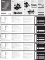
Hardware Review
A
Front View
1
Handle
2
Slide Release
3
LCD Display
4
LCD Controls
5
Port LEDs
6
Keyboard
7
Touchpad
8
Station/Port Switches
Rear View
1
Power Socket
2
Power Switch
3
Daisy-chain Port
4
KVM Ports
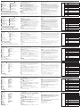
Hardware Installation
Standard Rack Mounting
B
To rack mount the switch, do the following:
1
While one person positions the switch in the rack and holds it in place, the
second person loosely screws the front brackets to the rack.
2
While the fi rst person still holds the switch in place, the second person slides
the L brackets into the switch's side mounting brackets, from the rear until the
bracket fl anges contact the rack, then screws the L brackets to the rack.
3
After the L brackets have been secured, tighten the front bracket screws.
Single Stage Installation
C
1
Use the grounding wire to connect the switch’s grounding terminal to a suitable
grounded object.
2
Plug an Ethernet cable from the network into the LAN port.
3
(Optional) Use the console cable provided with the package to connect a
keyboard, monitor, and mouse to the Console Port.
Note: The maximum distance between the switch and external monitor is 20 m.
4
For each of the computers you are installing, use a KVM cable set to connect a
KVM port to the computer's keyboard, video and mouse ports.
Note: The maximum distance between the switch and a computer is 10 m.
5
Plug the power cord into the CL5708I / CL5716I power socket and into an AC
power source.
6
Power on the CL5708I / CL5716I and then power on the computers.
Operation
The CL5708I / CL5716I provide three port selection methods to access the
computers on the installation: Manual, OSD (on-screen display), and Hotkeys.
Manual
For manual port selection, simply press the Port Switch pushbutton on the keyboard
module that corresponds to the device you want to access.
OSD
D
The On Screen Display (OSD) is a menu driven method to handle computer control
and switching operations. Before the OSD main screen displays, a login screen
appears requiring a password. If this is the fi rst time that the OSD is being accessed,
or if the password has not been set, please use the default username and password,
administrator / password to log in.
All procedures start from the OSD Main Screen. At any time you can display the
Main Screen by tapping the OSD hotkey twice. The default hotkey is [Scroll Lock].
You can change the hotkey to the Ctrl key or the Alt key if you like.
When you invoke the OSD, a screen similar to the one above appears.
Hotkeys:
All hotkey operations begin by invoking Hotkey mode. There are two possible
keystroke sequences used to invoke Hotkey mode, though only one can be
operational at any given time:
Num Lock and Minus Keys (Default) / Ctrl and F12 Keys (Alternate)
1. Hold down the Num Lock key or the Ctrl key
2. Press and release the minus key or the F12 key
3. Release the Num Lock or the Ctrl key: [Num Lock] + [-] or [Ctrl] + [F12]
Commutateur KVM sur IP LCD CL5708I / CL5716I
www.aten.com
www.aten.com
www.aten.com
www.aten.com
9
External Mouse Port
10
Power LED
11
Rack Mounting Brackets
12
Lock LEDs
13
Reset Switch
14
Firmware Upgrade Section
15
USB Port
16
LED Illumination Light
4
5
Grounding Terminal
6
LAN Port
7
External Console Port
Hotkey Summary Table
[Num Lock] +
[-] or [Ctrl] +
[F12]
[B] Toggles the beeper on or off.
[Esc] or
[Spacebar]
Exits hotkey mode.
[F1] Set Operating System to Windows.
[F2] Set Operating System to Mac.
[F3] Set Operating System to Sun.
[F5]
Performs a keyboard / mouse reset on the
target computer.
[H]
Toggles the Quick Hotkey invocation keys between
[Ctrl] + [F12] and [Num Lock] + [-].
[R] [Enter]
This administrator only hotkey restores the switch’s
default values.
[SN] [PN]
[Enter]
Switches access to the computer that corresponds
to that port ID.
[A] [Enter] or
[Q] [Enter]
Invokes Auto Scanmode. When Auto Scan mode
is in effect, [P] or left-click pauses auto-scanning.
When auto-scanning is paused, pressing any key
or another left-click resumes auto-scanning.
[T]
Toggles the OSD Hotkey between [Ctrl] [Ctrl] and
[Scroll Lock] [Scroll Lock].
[
←]
Invokes Skip mode and skips from the current port
to the fi rst accessible port previous to it.
[
→
]
Invokes Skip mode and skips from the current port
to the next accessible port.
Présentation du matériel
A
Vue de devant
1
Poignée
2
Dégagement latéral
3
Écran LCD
4
Commandes LCD
5
LED de port
6
Clavier
7
Pavé tactile
8
Commutateurs de station / port
Vue de derrière
1
Prise d'alimentation
2
Bouton d'alimentation
3
Port de chaîne
4
Ports KVM
Installation du matériel
Montage en rack standard
B
Pour monter le commutateur en rack, effectuez ce qui suit :
1
Pendant qu'une personne positionne le commutateur dans le rack et le tient en
place, une deuxième desserre les crochets à l'avant du rack.
2
Pendant qu'une personne maintient le commutateur en place, une deuxième fait
glisser les crochets en L dans les crochets de montage latéraux du commutateur
depuis l'arrière jusqu'à ce que les brides des crochets touchent le rack, puis visse
les crochets en L sur le rack.
3
Une fois les crochets en L fi xés, serrez les vis des crochets à l'avant.
Installation en une seule étape
C
1
Utilisez le fi l de mise à la terre pour raccorder la borne de mise à la terre du
commutateur à un objet relié à une terre appropriée.
2
Branchez un câble Ethernet du réseau au port LAN.
3
(Facultatif) Utilisez le câble console fourni dans l’emballage pour raccorder un
clavier, un moniteur et une souris au port Console.
Remarque : La distance maximale entre le commutateur et le moniteur externe
est de 20 m.
4
Pour chacun des ordinateurs que vous installez, utilisez un jeu de câbles KVM
pour connecter un port KVM aux ports clavier, vidéo et souris de l’ordinateur.
Remarque : La distance maximale entre le commutateur et un ordinateur est de
10 m.
5
Raccordez le cordon d'alimentation à la prise d'alimentation du CL5708I /
CL5716I et à une source d'alimentation CA.
6
Mettez le CL5708I / CL5716I sous tension puis allumez les ordinateurs.
Fonctionnement
Le CL5708I / CL5716I propose trois méthodes de sélection des ports pour accéder
aux ordinateurs sur l'installation : Une méthode manuelle, un menu à l'écran (OSD)
et des raccourcis.
Méthode manuelle
Pour la sélection manuelle du port, appuyez simplement sur le bouton de
commutation du Port sur le module clavier, correspondant à l'appareil auquel vous
souhaitez accéder.
OSD
D
Le menu à l’écran (OSD) est une méthode à base de menus pour effectuer les
opérations de contrôle de l’ordinateur et de commutation. Avant que l'écran
principal du menu OSD s'affi che, un écran de connexion vous demande un mot
de passe. Si c'est la première fois que vous accédez au menu OSD, ou si le mot de
passe n'a pas été défi ni, veuillez utiliser le nom d’utilisateur « administrator » et le
mot de passe par défaut « password » pour la connexion.
Toutes les procédures se démarrent depuis l’écran principal de l’OSD. À tout
moment, vous pouvez affi cher le menu à l’écran en appuyant deux fois sur le
raccourci OSD. La touche de raccourci par défaut est [Arrêt défi l]. Vous pouvez
modifi er le raccourci au profi t de la touche Ctrl ou de la touche Alt si vous le voulez.
Lorsque vous appelez l’OSD, un menu similaire à celui ci-dessus apparait.
Raccourcis :
Toutes les opérations à base de raccourcis comment par un appel du mode
Raccourci. Il y a deux séquences de touches possibles pour appeler le mode
Raccourci, mais une seule peut être opérationnelle à la fois :
Touches Verr Num et Moins (Par défaut) / touches Ctrl et F12 (Autrement)
1. Maintenez enfoncée la touche Verr Num ou la touche Ctrl
2. Appuyez sur la touche Moins ou sur la touche F12 et relâchez
3. Relâchez la touche Verr Num ou la touche Ctrl : [Verr Num] + [-] ou [Ctrl] + [F12]
9
Port souris externe
10
LED d'alimentation
11
Supports de montage en rack
12
DEL de verrouillage
13
Bouton de réinitialisation
14
Section de mise à niveau du fi rmware
15
Port USB
16
Éclairage DEL
Tableau de résumé des raccourcis
[Verr Num] +
[-] ou [Ctrl] +
[F12]
[B]
Active ou désactive successivement le biper.
[Esc] ou
[Espace]
Quitte le mode Raccourci.
[F1]
Règle le système d’exploitation sur Windows.
[F2]
Règle le système d’exploitation sur Mac.
[F3]
Règle le système d’exploitation sur Sun.
[F5]
Effectue une réinitialisation du clavier et de la souris
sur l'ordinateur cible.
[H]
Bascule les touches d’appel rapide des raccourcis entre
[Ctrl] + [F12] et [Verr Num] + [-].
[R] [Entrée]
Cette touche de raccourci réservée à l’administrateur
restaure les valeurs par défaut du commutateur.
[SN] [PN]
[Entrée]
Bascule pour accéder à l’ordinateur qui correspond à
ce port ID.
[A] [Entrée]
ou [Q]
[Entrée]
Appelle le mode de recherche automatique. Lorsque le
mode de recherche automatique est effectif, [P] ou un
clic gauche permet de mettre en pause la recherche.
Lorsque la recherche automatique est en pause, l’appui
sur n’importe quelle touche ou un autre clic gauche
permet de reprendre la recherche automatique.
[T]
Bascule le raccourci du menu OSD entre [Ctrl] [Ctrl] et
[Arrêt défi l] [Arrêt défi l].
[
←]
Appelle le mode Sauter et saute du port actuel au
premier port accessible précédent.
[
→
]
Appelle le mode Sauter et saute du port actuel au
premier port accessible suivant.
LCD-KVM-over-IP-Switch CL5708I / CL5716I
Hardwareübersicht
A
Ansicht von vorne
1
Griff
2
Schiebefreigabe
3
LCD-Display
4
LCD-Bedienelemente
5
Anschluss-LEDs
6
Tastatur
7
Touchpad
8
Station/Port-Schalter
Ansicht von hinten
1
Netzanschluss
2
Netzschalter
3
Daisy-Chain-Port
4
KVM-Ports
Hardwareinstallation
Standardrackmontage
B
Gehen Sie zur Montage des Switch in einem Rack wie folgt vor:
1
Während eine Person den Switch im Rack ausrichtet und hält, verschraubt die
zweite Person die frontseitigen Halterungen lose mit dem Rack.
2
Während die erste Person den Switch immer noch festhält, schiebt die zweite
Person die L-Halterungen von hinten in die seitlichen Montagehalterungen des
Switch, bis die Halterungsfl ansche das Rack berühren; anschließend schraubt sie
die L-Halterungen an das Rack.
3
Ziehen Sie nach Befestigung der L-Halterungen die Schrauben der vorderen
Halterung fest.
Einzelne Stage installieren
C
1
Verbinden Sie die Erdungsklemme des Switch über ein Erdungskabel mit einem
geeigneten geerdeten Objekt.
2
Schließen Sie ein Ethernet-Kabel vom Netzwerk an den LAN-Anschluss an.
3
(Optional) Schließen Sie über das mitgelieferte Konsolenkabel eine Tastatur,
einen Monitor und eine Maus an den Konsolenanschluss an.
Hinweis: Der maximale Abstand zwischen Switch und externem Monitor beträgt
20 m.
4
Verwenden Sie bei jedem Computer, den Sie installieren, ein KVM-Kabelset
zur Verbindung eines KVM-Anschlusses mit den Tastatur-, Video- und
Mausanschlüssen des Computers.
Hinweis: Der maximale Abstand zwischen Switch und Computer beträgt 10 m.
5
Schließen Sie das Netzkabel an den Stromanschluss des CL5708I / CL5716I und
eine Steckdose an.
6
Schalten Sie den CL5708I / CL5716I und dann die Computer ein.
Bedienung
Der CL5708I / CL5716I bietet drei Portauswahlmethoden zum Zugreifen auf
die Computer in der Installation: Manuell, per OSD (Bildschirmmenü) und über
Tastenkombinationen.
Manuell
Bei der manuellen Portauswahl drücken Sie einfach die dem Zielgerät entsprechende
Portwechseltaste am Tastaturmodul.
OSD
D
Über das Bildschirmmenü (OSD) können Sie den Computer steuern und
Wechsel durchführen. Vor Anzeige des OSD-Hauptbildschirms erscheint ein
Anmeldebildschirm, der eine Kennworteingabe erfordert. Wenn Sie das OSD zum
ersten Mal aufrufen oder das Kennwort nicht eingerichtet wurde, Bitte benutzen Sie
für die Anmeldung den Standard-Benutzernamen: administrator / password für die
Anmeldung.
Alle Vorgänge beginnen am OSD-Hauptbildschirm. Sie können den Hauptbildschirm
jederzeit anzeigen, indem Sie die OSD-Schnelltaste zweimal drücken. Die
Standardschnelltaste ist die [Rollen-Taste]. Auf Wunsch können Sie die Strg- oder
Alt-Taste als Schnelltaste festlegen.
Wenn Sie das OSD aufrufen, erscheint ein Bildschirm wie der oben gezeigte.
Schnelltasten:
Alle Schnelltastenoperationen beginnen durch Aktivierung des Schnelltastenmodus.
Es gibt zwei mögliche Tastenfolgen zur Aktivierung des Schnelltastenmodus, wobei
immer nur eine aktiv sein kann:
Num-Lock- und Minus-Taste (Standard) / Strg- und F12-Taste (alternativ)
1. Halten Sie Num-Lock- oder Strg-Taste gedrückt
2. Drücken Sie kurz die Minus- oder F12-Taste
3. Num-Lock- oder Strg-Taste loslassen: [Num Lock] + [-] oder [Strg] + [F12]
Übersichtstabelle der Tastenkombinationen
[Num Lock] +
[-] oder [Strg] +
[F12]
[B] Schaltet den Signalton ein oder aus.
[Esc] oder
[Leertaste]
Beendet den Schnelltastenmodus.
[F1] Stellt das Betriebssystem auf Windows ein.
[F2] Stellt das Betriebssystem auf Mac ein.
[F3] Stellt das Betriebssystem auf Sun ein.
[F5]
Führt eine Tastatur- / Mausrücksetzung am
Zielcomputer durch.
[H]
Wechselt die Schnelltasten-Aktivierungstasten
zwischen [Strg] + [F12] und [Num Lock] + [-].
[R] [Enter]
Diese nur vom Administrator nutzbare
Tastenkombination stellt die Standardwerte des Switch
wieder her.
[SN] [PN]
[Enter]
Wechselt den Zugriff auf den Computer, der der Port-
ID entspricht.
[A] [Enter]
oder [Q]
[Enter]
Aktiviert den automatischen Suchmodus. Wenn
der automatische Suchmodus aktiv ist, wird die
automatische Suche mit [P] oder Linksklick angehalten.
Wenn die automatische Suche angehalten ist, können
Sie ihn durch Betätigung einer beliebigen Taste oder
durch einen weiteren Linksklick fortsetzen.
[T]
Wechselt die OSD-Tastenkombination zwischen [Strg]
[Strg] und [Rollen-Taste] [Rollen-Taste].
[
←]
Aktiviert den Springmodus und springt vom aktuellen
Port zu dem zuvor zuerst zugänglichen Port.
[
→
]
Aktiviert den Springmodus und springt vom aktuellen
Port zu dem nächsten zugänglichen Port.
9
Anschluss für externe Maus
10
Betriebsanzeige-LED
11
Rackmontagehalterungen
12
Sperr-LEDs
13
Reset-Schalter
14
Firmware-Aktualisierungsauswahl
15
USB-Port
16
LED-Beleuchtung
5
Erdungsklemme
6
LAN-Port
7
Externe-Konsole-Port
5
Borne de terre
6
Port LAN
7
Port console externe
Conmutador KVM LCD sobre IP CL5708I / CL5716I
Switch KVM over IP CL5708I / CL5716I LCD
Descrizione hardware
A
Vista anteriore
1
Maniglia
2
Rilascio a scorrimento
3
Display LCD
4
Controlli LCD
5
LED porta
6
Tastiera
7
Touchpad
8
Interruttori stazione/porta
Vista posteriore
1
Presa di alimentazione
2
Interruttore di alimentazione
3
Porta di interconnessione
4
Porte KVM
Installazione dell'hardware
Montaggio su rack standard
B
Per il montaggio su rack dello switch, agire come segue:
1
Mentre una persona colloca e mantiene in posizione lo switch nel rack, la
seconda persona avvita senza serrare le staffe anteriori sul rack.
2
Mentre la prima persona continua a mantenere in posizione lo switch, la
seconda persona fa scorrere le staffe a L nelle staffe di montaggio laterali dello
switch dal retro fi nché le fl ange della staffa non vengono a contatto con il rack,
quindi avvita le staffe a L sul rack.
3
Una volta fi ssate le staffe a L, serrare le viti della staffa anteriore.
Installazione della fase singola
C
1
Utilizzare il cavo di messa a terra per collegare il terminale di messa a terra dello
switch ad un appropriato elemento di messa a terra.
2
Collegare un cavo Ethernet dalla rete nella porta LAN.
3
(Opzionale) Utilizzare il cavo console in dotazione per collegare una tastiera, un
monitor e un mouse alla porta console.
Nota: La distanza massima tra lo switch e il monitor esterno è 20 m.
4
Per ogni computer installato, utilizzare un set di cavi KVM per collegare una
porta KVM alle porte di tastiera, video e mouse del computer.
Nota: La distanza massima tra lo switch e un computer è 10 m.
5
Collegare il cavo di alimentazione alla presa di alimentazione CL5708I / CL5716I
e ad una sorgente di alimentazione CA.
6
Accendere CL5708I / CL5716I, quindi accendere i computer.
Funzionamento
Il CL5708I / CL5716I dispone di tre metodi di selezione porta per accedere ai
computer per l'installazione: Manuale, OSD e tasti di scelta rapida.
Manuale
Per la selezione manuale della porta basta premere sulla tastiera il tasto di
commutazione porte che corrisponde al dispositivo a cui si vuole accedere.
OSD
D
L'OSD è un metodo a menu per gestire le operazioni di controllo e commutazione
del computer. Prima di visualizzare la schermata principale del menu OSD, viene
visualizzata una schermata di login che richiede una password. Se si accede al menu
OSD per la prima volta oppure non si è ancora impostata la password, Per accedere
usare il nome utente e la password predefi niti: administrator / password.
Tutte le procedure iniziano dalla schermata principale dell'OSD. In qualsiasi
momento è possibile visualizzare la schermata principale toccando il tasto di scelta
rapida dell'OSD. Il tasto di scelta rapida predefi nito è [BLOC SCORR]. È possibile
modifi care il tasto di scelta rapida sul tasto Ctrl o Alt.
Quando si richiama l'OSD, viene visualizzata una schermata simile a quella
precedente.
Tasti di scelta rapida:
Tutte le operazioni dei tasti di scelta rapida iniziano richiamando la modalità Tasto di
scelta rapida. Per richiamare la modalità Tasto di scelta rapida, vi sono due possibili
sequenze di tasti, sebbene sono uno è operativo in un determinato momento:
Tasti Bloc num e meno (predefi nito) / Tasti Ctrl e F12 (alternati)
1. Tenere premuto il tasto Bloc num o Ctrl
2. Premere e rilasciare il tasto meno o F12
3. Rilasciare il tasto Bloc num o Ctrl: [Bloc num] + [-] o [Ctrl] + [F12]
9
Porta mouse esterno
10
LED alimentazione
11
Staffe di montaggio su rack
12
LED di blocco
13
Interruttore di ripristino
14
Sezione di aggiornamento fi rmware
15
Porta USB
16
Spia di illuminazione LED
5
Terminale di massa
6
Porta LAN
7
Porta console esterna
Tabella di riepilogo tasti di scelta rapida
[Bloc num] +
[-] o [Ctrl] +
[F12]
[B] Attiva o disattiva il cicalino.
[ESC] o [Barra
spaziatrice]
Esce dalla modalità Tasto di scelta rapida.
[F1] Imposta Sistema operativo su Windows.
[F2] Imposta Sistema operativo su Mac.
[F3] Imposta Sistema operativo su Sun.
[F5]
Esegue un ripristino di tastiera/mouse sul
computer target.
[H]
Porta i tasti di richiamo Tasto di scelta rapida tra [Ctrl]
+ [F12] e [Bloc num] + [-].
[R] [Invio]
Questo tasto di scelta rapida solo per l'amministratore
ripristina i valori predefi niti dello switch.
[SN] [PN]
[Invio]
Gli switch accedono al computer corrispondente all'ID
porta.
[A] [Invio] o
[Q] [Invio]
Richiama la modalità Scansione automatica. Quando la
modalità Scansione automatica è attiva, [P] o il clic del
tasto sinistro interrompono la scansione automatica.
Quando si interrome la scansione automatica,
premendo un tasto o facendo un altro clic con il tasto
sinistro si riprende la scansione automatica.
[T]
Commuta il tasto di scelta rapida OSD tra [Ctrl] [Ctrl]
e [BLOC SCORR] [BLOC SCORR].
[
←]
Richiama la modalità Salta e passa dalla porta attuale
alla prima porta accessibile precedente.
[
→
]
Richiama la modalità Salta e passa dalla porta attuale
alla successiva porta accessibile.
Resumen de hardware
A
Vista frontal
1
Asa
2
Deslizador de desbloqueo
3
Pantalla LCD
4
Controles LCD
5
LEDs de puerto
6
Teclado
7
Panel táctil
8
Estación/Conmutador de puertos
Vista posterior
1
Toma de alimentación
2
Interruptor de alimentación
3
Puerto para conexión en cadena
4
Puertos KVM
Instalación del hardware
Montaje estándar en bastidor
B
Para montar el conmutador en un bastidor, haga lo siguiente:
1
Mientras que una persona coloca el conmutador en el bastidor y lo mantiene
en su lugar, la segunda persona atornilla sin apretar los soportes frontales en el
bastidor.
2
Mientras la primera persona aún mantiene el conmutador en su lugar, la
segunda persona desliza los soportes en L en los soportes de montaje laterales
del conmutador, desde la parte posterior hasta que las bridas del soporte entren
en contacto con el bastidor, luego aprieta los tornillos de los soportes en L al
bastidor.
3
Después de haber asegurado los soportes en L, apriete los tornillos del soporte
frontal.
Instalación en una sola etapa
C
1
Utilice el cable de conexión a tierra para conectar el terminal de conexión a tierra
del conmutador a un objeto adecuadamente conectado a tierra.
2
Conecte un cable Ethernet desde la red al puerto LAN.
3
(Opcional) Utilice el cable de consola suministrado con el paquete para conectar
un teclado, un monitor y un ratón al puerto de consola.
Nota: La distancia máxima entre el conmutador y el monitor externo es de 20 m.
4
Para cada uno de los PCs que está instalando, utilice un juego de cables KVM
para conectar un puerto KVM a los puertos de teclado, vídeo y ratón del PC.
Nota: La distancia máxima entre el conmutador y el ordenador es de 10 m.
5
Conecte el cable de alimentación en la toma de corriente del CL5708I / CL5716I
y en una fuente de alimentación de CA.
6
Encienda el CL5708I / CL5716I y luego encienda los PCs.
Funcionamiento
El CL5708I / CL5716I proporciona tres métodos de selección de puertos para
acceder a los equipos de la instalación: Manual, OSD (visualización en pantalla) y
Teclas de acceso rápido.
Manual
Para la selección manual de puertos, simplemente presione el botón del conmutador
de puerto en el módulo de teclado que corresponde al dispositivo al que desea
acceder.
OSD
D
La visualización en pantalla (OSD) es un método accionado por menús para manejar
operaciones de control y conmutación por ordenador. Antes de que aparezca la
pantalla principal del OSD, una pantalla de inicio de sesión aparece solicitando
una contraseña. Si es la primera vez que se accede al OSD, o si la contraseña no
se ha confi gurado, Para iniciar sesión, utilice el nombre de usuario y la contraseña
predeterminados: administrator y password, respectivamente.
Todos los procedimientos comienzan desde la pantalla principal del OSD. En
cualquier momento puede mostrar la pantalla principal tocando la tecla de acceso
directo OSD dos veces. La tecla de acceso directo predeterminada es [Bloqueo de
desplazamiento]. Puede cambiar la tecla de acceso rápido a la tecla Ctrl o la tecla
Alt si lo desea.
Cuando abre el OSD, aparece una pantalla similar a la anterior.
Teclas de acceso rápido:
Todas las operaciones de teclas de acceso directo comienzan activando el modo de
tecla de acceso rápido. Hay dos posibles secuencias de pulsación de teclas utilizadas
para recurrir al modo de tecla de acceso rápido, aunque sólo una puede estar
operativa en un momento dado:
Las teclas Bloq Num y menos (Predeterminado) / Las teclas Ctrl y F12
(Alternativas)
1. Mantenga presionada la tecla Bloq Num o la tecla Ctrl
2. Presione y suelte la tecla menos o la tecla F12
3. Suelte el bloqueo numérico o la tecla Ctrl: [Bloq Num] + [-] o [Ctrl] + [F12]
5
Terminal de toma de tierra
6
Puerto LAN
7
Puerto de consola externo
Tabla resumen de teclas de acceso directo
[Bloq Num] + [-]
o [Ctrl] + [F12]
[B] Activa o desactiva el pitido.
[Esc] o [Barra
espaciadora]
Sale del modo de teclas de acceso rápido.
[F1] Establecer el sistema operativo en Windows.
[F2] Establecer sistema operativo en Mac.
[F3] Establecer sistema operativo en Sun.
[F5]
Realiza un reinicio del teclado / ratón en el
PC de destino.
[H]
Alterna las teclas de llamada rápida de teclas de
acceso rápido entre [Ctrl] + [F12] y [Bloq Num] + [-].
[R] [Entrar]
Esta tecla de acceso directo solo para el administrador
restaura los valores predeterminados del conmutador.
[SN] [NP]
[Entrar]
Cambia el acceso al PC que corresponde a ese ID de
puerto.
[A] [Entrar] o
[Q] [Entrar]
Activa el modo de escaneo automático. Cuando el
modo de exploración automática está activado, [P] o
hacer clic con el botón izquierdo pausa la búsqueda
automática. Cuando la exploración automática está en
pausa, al presionar cualquier tecla o hacer clic con el
botón izquierdo se reanuda la exploración automática.
[T]
Activa o desactiva la tecla de acceso directo al OSD
entre [Ctrl] [Ctrl] y [Bloq Num] [Bloq Num].
[
←]
Activa el modo Omitir y salta del puerto actual al
primer puerto accesible anterior al mismo.
[
→
]
Activa el modo Omitir y salta del puerto actual al
siguiente puerto accesible.
9
Puerto externo del ratón
10
LED de alimentación
11
Soportes de montaje en bastidor
12
LED de bloqueo
13
Interruptor de reinicio
14
Sección de actualización del fi rmware
15
Puerto USB
16
Luz de iluminación LED
Support and Documentation Notice
All information, documentation, fi rmware,
software utilities, and specifi cations contained in
this package are subject to change without prior
notifi cation by the manufacturer.
To reduce the environmental impact of our
products, ATEN documentation and software can
be found online at
http://www.aten.com/download/
Technical Support
www.aten.com/support
이 기기는 업무용(A급) 전자파적합기기로서 판매자 또는 사용자는 이 점을
주의하시기 바라며, 가정외의 지역에서 사용하는 것을 목적으로 합니다.
Scan for
more information
EMC Information
FEDERAL COMMUNICATIONS COMMISSION INTERFERENCE
STATEMENT:
This equipment has been tested and found to comply with the limits
for a Class A digital device, pursuant to Part 15 of the FCC Rules.
These limits are designed to provide reasonable protection against
harmful interference when the equipment is operated in a commercial
environment. This equipment generates, uses, and can radiate radio
frequency energy and, if not installed and used in accordance with
the instruction manual, may cause harmful interference to radio
communications. Operation of this equipment in a residential area
is likely to cause harmful interference in which case the user will be
required to correct the interference at his own expense.
FCC Caution: Any changes or modifi cations not expressly approved by
the party responsible for compliance could void the user's authority to
operate this equipment.
Warning: Operation of this equipment in a residential environment
could cause radio interference.
This device complies with Part 15 of the FCC Rules. Operation is subject
to the following two conditions:(1) this device mat not cause harmful
interference, and(2) this device must accept any interference received,
including interference that may cause undesired operation.
Important. Before proceeding, download the Installation and
Operation Manual by visiting the website, www.aten.com and
navigating to the product page. The manual includes important
warnings, loading specifi cations and grounding instructions.
A
Package Contents
1 CL5708I / CL5716I LCD KVM over IP Switch with
standard Rack Mount Kit
2 Custom KVM Cable Sets
1 5-in-1 USB / PS/2 Console Cable
1 Firmware Upgrade Cable
1 Power Cord
1 User Instructions
B
D
Standard Rack Mounting
OSD
C
Single Stage Installation
Rear View
Front View
16
2
1
2
4
3
5
6
14
15
13
12
11
10
9
8
7
EXIT I LIGHT
Press the Exit/Light pushbutton for
two seconds to turn the LED light
ON or Off. (Default: On)
Hardware Review
321
4
765
5
1
6
4
3
2
6
1
2
La pagina si sta caricando...
-
 1
1
-
 2
2


in altre lingue
- English: ATEN CL5708I Quick start guide
- français: ATEN CL5708I Guide de démarrage rapide
- español: ATEN CL5708I Guía de inicio rápido
- Deutsch: ATEN CL5708I Schnellstartanleitung
- русский: ATEN CL5708I Инструкция по началу работы
- português: ATEN CL5708I Guia rápido
- 日本語: ATEN CL5708I クイックスタートガイド