ProLights STUDIOCOBPLUSUV Manuale utente
- Categoria
- Stroboscopi
- Tipo
- Manuale utente

USER MANUAL
MANUALE UTENTE
STUDIOCOBPLUSUV
EN - IT
DIFFUSED LIGHT PROJECTOR

STUDIOCOBPLUSUV
2
All rights reserved by Music & Lights S.r.l. No part of this instruction manual may be
reproduced in any form or by any means for any commercial use.
In order to improve the quality of products, Music&Lights S.r.l. reserves the right to modify the
characteristics stated in this instruction manual at any time and without prior notice.
All revisions and updates are available in the ‘manuals’ section on site www.musiclights.it
REV.01-04/18

1
STUDIOCOBPLUSUV
Packing content
• STUDIOCOBPLUSUV
• Mount bracket
• Power cable
• User manual
TABLE OF CONTENTS
Safety
General instructions
Warnings and installation precautions
1 Introduction
1. 1 Description
1. 2 Technical specifications
1. 3 Operating elements and connections
2 Installation
2. 1 Mounting
3 Functions and settings
3. 1 Operation
3. 2 Basic
3. 3 Menu structure
3. 4 Auto show
3. 5 Static mode
3. 6 Master/Slave mode
3. 7 Linking
3. 8 DMX mode
3. 9 DMX addressing
3. 10 Connection of the DMX line
3. 11 Construction of the DMX termination
3. 12 DMX control
3. 13 Dimmer
3. 14 Back light
3. 15 Fixture information
3. 16 LED frequency
3. 17 Fan mode
3. 18 KeyLock
3. 19 Factory Reset
3. 20 RDM
4 Maintenance
4. 1 Maintenance and cleaning the unit
4. 2 Trouble shooting
2
2
3
3
5
6
7
7
8
9
9
9
9
9
10
11
11
12
13
13
13
13
13
14
14
14
15
15

STUDIOCOBPLUSUV
2
SAFETY
General instruction
• The products referred to in this manual conform to the European Community Directives and are there-
fore marked with .
• The unit is supplied with hazardous network voltage (230V~). Leave servicing to skilled personnel only.
Never make any modifications on the unit not described in this instruction manual, otherwise you will
risk an electric shock.
• Connection must be made to a power supply system fitted with efficient earthing (Class I appliance ac-
cording to standard EN 60598-1). It is, moreover, recommended to protect the supply lines of the units
from indirect contact and/or shorting to earth by using appropriately sized residual current devices.
• The connection to the main network of electric distribution must be carried out by a qualified electrical
installer. Check that the main frequency and voltage correspond to those for which the unit is designed
as given on the electrical data label.
• This unit is not for home use, only professional applications.
• Never use the fixture under the following conditions:
- in places subject to vibrations or bumps;
- in places with a temperature of over 40 °C.
• Make certain that no inflammable liquids, water or metal objects enter the fixture.
• Do not dismantle or modify the fixture.
• All work must always be carried out by qualified technical personnel. Contact the nearest sales point for
an inspection or contact the manufacturer directly.
• If the unit is to be put out of operation definitively, take it to a local recycling
plant for a disposal which is not harmful to the environment.
Warnings and installation precautions
• If this device will be operated in any way different to the one described in this manual, it may suffer
damage and the guarantee becomes void. Furthermore, any other operation may lead to dangers like
short circuit, burns, electric shock, etc.
• Before starting any maintenance work or cleaning the projector, cut off power from the main supply.
• Always additionally secure the projector with the safety rope. When carrying out any work, always com-
ply scrupulously with all the regulations (particularly regarding safety) currently in force in the country
in which the fixture’s being used.
• Install the fixture in a well ventilated place.
• Keep any inflammable material at a safe distance from the fixture.
• Shields, lenses or ultraviolet screens shall be changed if they have become damaged to such an extent
that their effectiveness is impaired.
• The lamp (LED) shall be changed if it has become damaged or thermally deformed.
• Never look directly at the light beam. Please note that fast changes in lighting, e. g. flashing light, may
trigger epileptic seizures in photosensitive persons or persons with epilepsy.
• Do not touch the product’s housing when operating because it may be very hot.
WARNING! Before carrying out any operations with the unit, carefully read this instruction
manual and keep it with cure for future reference. It contains important information about
the installation, usage and maintenance of the unit.

3
STUDIOCOBPLUSUV
- 1 - INTRODUCTION
1.1 DESCRIPTION
STUDIOCOB PLUS is a powerful, and incredibly versatile, IP65 rated LED par. Fusing the old and the new
it pairs a COB LED source with a traditional parabolic reflector to deliver a proper PAR replacement with a
homogenized output, single shadow, and flexible lens options.
1.2 TECHNICAL SPECIFICATIONS
LIGHT SOURCE
• Source: 457nm 108W COB UV Led
• CRI: 55,4Ra
• R9: 5
• Luminous Flux: (18°) without filter:137.21lm (18°) with filter:128.92 lm (38°) without filter:129.07 lm
(38°) with filter:120.63lm
• Lux: (18°) 8.963 lux - (38°) 2.018lux @5m without filter
• Lux: (18°) 7.481 lux - (38°) 1.83lux @5m with filter
• Source Life Expectancy: >50.000 h
OPTICS
• Beam Angle: (18°) 15.93° - (18°)with filter 16.49° - (38°) 35.6° - (38°) with filter 36.06°
• Field Angle: (18°) 28.2° - (18°)with filter 30.3° - (38°) 66.1° - (38°) with filter 69.1°
• Lens Diameter: 149.5mm
• Lens Type: UV PMMA lens
• Additional Optics: 18°lens on board and 38°lens in the package
COLOR SYSTEM
• Color Wheel: Virtual color wheel with presets
DYNAMIC EFFECTS
• Manual Color Mode: Manual adjustment of dimmer and strobe
BODY
• Tilt Angle:
• Body: Aluminium body
• Body Color: Black
CONTROL
• Protocols: DMX512, RDM
• DMX Channels: 1/2/5ch
• RDM: RDM ready for fixture remote monitor and settings
• Display: Black OLED touch display
• Firmware Upgrade: Yes, via USB-DMX interface (UPBOX1) not included
• Master/Slave: for synchronized operation of more units linked in a chain
ELECTRONICS
• Dimmer: Linear 0~100% electronic dimmer
• Dimmer Curves: 4 Different dimming curves available

STUDIOCOBPLUSUV
4
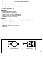
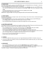
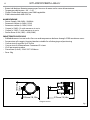
187mm/
7,36in
259mm/10,10in 370mm/14,56in
• Strobe/Shutter: 1-28 Hz, electronic
• Battery Backup: Battery backup for user operation without connecting to the main power
• Operating Temperature: -20° ~ +45°
• Flicker: Flicker free frequency with adjustable PWM
• Selectable PWM: 600~25K Hz
ELECTRICAL
• Power Supply: 100-240V – 50/60Hz
• Power Consumption (at 230V): 132W
• Power Consumption (at 120V): 133W
• Output (at 230V): 13 units on a single power line
• Output (at 120V): 7 units on a single power line
• Power factor: 0.98 (120V) - 0.90 (230V)
PHYSICAL
• Cooling: Low noise fan Pressure and temperature balance through GORE membrane vents
• Suspension And Fixing: Hanging bracket suitable for safe hanging and positioning
• Signal Connection: 5p IP in/out
• Power Connection: IP in/out power connector
• IP: 65 for outdoor events
• Dimensions (WxHxD): 258.5*257*353.6mm
• Weight: 5kg
Technical drawing
Fig.1

5
STUDIOCOBPLUSUV
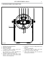
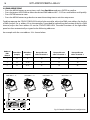
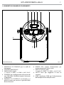
1.3 OPERATING ELEMENTS AND CONNECTIONS
Rear panel Fig.2
1. KNOB for the mounting bracket
2. MOUNTING BRACKET
3. DMX IN (5-pole XLR):
1 = massa, 2 = DMX -, 3 = DMX +, 4 N/C, 5 N/C
4. POWER IN (PowerCON TRUE IN):
for connection to a socket (100-240V~/50-
60Hz) via the supplied mains cable
5. CONTROL PANEL with display and 4 touch
buttons used to access the control panel
functions and manage them
6. POWER OUT: connect to supply power to the
next unit
7. DMX OUT (5-pole XLR):
1 = ground, 2 = DMX-, 3 = DMX+, 4 N/C, 5 N/C
8. SAFETY HOLE to attach safety cable
9. GORE: GORE membrane vents for pressure
and temperature balance
43
5
6
7 1
2
8 9

STUDIOCOBPLUSUV
6
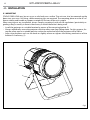
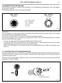
Fig.3
1
2
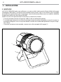
- 2 - INSTALLATION
2.1 MOUNTING
STUDIOCOBPLUSUV may be set up on a solid and even surface. The unit can also be mounted upside
down to a cross arm. For fixing, stable mounting clips are required. The mounting place must be of suf-
ficient stability and be able to support a weight of 10 times of the unit’s weight.
When carrying out any installation, always comply scrupulously with all the regulations (particularly re-
garding safety) currently in force in the country in which the fixture’s being used.
• Install the projector at a suitable location by means of the mounting bracket (2).
• Always additionally secure the projector with the safety rope from falling down. For this purpose, fas-
ten the safety rope at a suitable position so that the maximum fall of the projector will be 20 cm.
• Adjust the projector and use the knob to slightly release or tighten the locking mechanism of the
bracket if is necessary (1).

7
STUDIOCOBPLUSUV
Mode
Enter
Up
Down
- 3 - FUNCTIONS AND SETTINGS
3.1 OPERATION
Connect the supplied main cable to a socket (100-240V~/50-60Hz). Then the unit is ready for operation
and can be operated via a DMX controller or it independently performs its show program in succession.
To switch off, disconnect the mains plug from the socket. For a more convenient operation it is recom-
mended to connect the unit to a socket which can be switched on and off via a light switch.
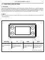
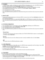
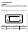
3.2 BASIC
Access control panel functions using the four panel touch buttons located directly underneath the black
OLED display (fig.4).
Fig.4 - Functions of the buttons
MODE (MENU) UP DOWN ENTER
Used to access the menu or
to return a previous menu
option
Navigates downwards through
the menu list and increases
the numeric value when in a
function
Navigates upwards through
the menu list and decreases
the numeric value when in
a function
Used to select and store the
current menu or confirm the
current function value or
option within a menu

STUDIOCOBPLUSUV
8
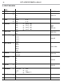
3.3 MENU STRUCTURE
MENU
1 DMX Address
ð
1 - 512 Default: 001
2 DMX Channel
ð
1 Ch
Default: 5 ch2 Ch
5 Ch
3 Static
ð
Dimmer 0 - 255
ð
Strobe 0 - 255
4 Auto Show
ð
Auto 1
ð
Speed (1 - 100)
Default:
AUTO4
SPEED=100
Auto 2
ð
Speed (1 - 100)
Auto 3
ð
Speed (1 - 100)
Auto 4
ð
Speed (1 - 100)
5 Master/Slave
ð
Master
Default: Slave
Slave
6 Dimmer Mode
ð
Off
Default: Off
Dimmer 1
Dimmer 2
Dimmer 3
7 LED Frequency
ð
600 Hz
Default: 1200Hz
1200 Hz
2000 Hz
4000 Hz
25 KHz
8 Fan Mode
ð
Auto Speed
Default: Auto
High Speed
9 Back Light
ð
On
Default: On
10 S
20 S
30 S
10 Key Lock
ð
On
Default: On
Off
11 Information
ð
Fixture Hours
ð
9999h
Version
ð
V1.0
UID
ð
15D0021D****
12 Reset Factory
ð
NO
YES

9
STUDIOCOBPLUSUV
3.4 AUTO SHOW
If no DMX control signal is present at the DMX INPUT, the unit independently runs through its show pro-
gramme provided that the blackout mode is switched off:
• Press the MENU button so many times until the display shows Auto Show, then press the ENTER button.
• Press the UP/DOWN button to switch between the show Auto 1 - Auto 4. The unit will operate in show
mode.
• Using the UP/DOWN button to select the desired run speed slow-fast 1 -100.
• Press the ENTER button to save the setting.
IMPORTANT: Programs Auto 1 - 4 are fully pre-programmed and will not be altered by changes.
3.5 STATIC MODE
This fixture has the ability to accept custom static color settings. Access these chases via the control panel
on the back of the fixture.
• Press the MENU button so many times until the display shows Static, then press the ENTER button.
• Select Dimmer, Strobe through the UP/DOWN buttons, then press ENTER.
• Press the MENU button to go back or to meet the waiting time to exit the setup menu.
3.6 MASTER/SLAVE MODE
This mode will allow you to link up the units together without a controller. Choose a unit to function as the
Master. The unit must be the first unit in line; other units will work as slave.
• Press the MENU button so many times until the display shows Master/Slave, then press ENTER.
• Using UP/DOWN buttons, select the desired mode and then press ENTER.
• Press the button MENU to go back or to meet the waiting time to exit the setup menu
• Use standard DMX cables to daisy chain your units together via the DMX connector on the rear of the
units. For longer cable runs we suggest a terminator at the last fixture (see page 13).
• Set on master fixture the desired program (see section 3.4).
• Set the slaves to the same DMX modes.
3.7 LINKING
1. Connect the DMX OUT of the master unit via 5-pole XLR cable to the DMX IN of the first slave unit.
2. Connect the DMX OUT of the first slave unit to the DMX IN of the second slave unit, etc. until all units
are connected in a chain.
3.8 DMX MODE
• Press the MENU button so many times until show Dmx Channel and press ENTER to confirm.
• Press the button UP/DOWN to select the desired DMX mode 1 Ch, 2 Ch o 5 Ch. Press ENTER button to store.
• Press the MENU button to go back or to meet the waiting time to exit the setup menu.
The tables on page 14 indicate the operating mode and DMX value.

STUDIOCOBPLUSUV
10
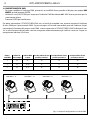
3.9 DMX ADDRESSING
• Press the MENU button so many times until show Dmx Address and press ENTER to confirm.
• Press the button UP/DOWN to select the desired DMX address 001 - 512. Press and hold to scroll quickly.
• Press ENTER button to store.
• Press the MENU button to go back or to meet the waiting time to exit the setup menu.
To able to operate the STUDIOCOBPLUSUV with a light controller, adjust the DMX start address for the first
a DMX channel. If e. g. address 33 on the controller is provided for controlling the function of the first DMX
channel, adjust the start address 33 on the STUDIOCOBPLUSUV. The other functions of the light effect
panel are then automatically assigned to the following addresses.
An example with the start address 33 is shown below:
Fig.5 - Example 4 DMX channels configuration
Number of
DMX
channels
Start address
(example)
DMX Address
occupied
Next possible start
address for unit No. 1
Next possible start
address for unit No. 2
Next possible start
address for unit No. 3
1 33 33 34 35 36
2 33 33-34 35 37 39
5 33 33-37 38 43 48
. . . . . . . . . . . .
DMX512 Controller
DMX Address: 33 DMX Address: 45DMX Address: 37 DMX Address: 41

11
STUDIOCOBPLUSUV
Fig.6
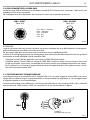
3.10 CONNECTION OF THE DMX LINE
DMX connection employs standard XLR connectors. Use shielded pair-twisted cables with 120Ω imped-
ance and low capacity.
The following diagram shows the connection mode:
ATTENTION
The screened parts of the cable (sleeve) must never be connected to the system’s earth, as this would
cause faulty fixture and controller operation.
Over long runs can be necessary to insert a DMX level matching amplifier.
For those connections the use of balanced microphone cable is not recommended because it cannot
transmit control DMX data reliably.
• Connect the controller DMX input to the DMX output of the first unit.
• Connect the DMX output to the DMX input of the following unit. Connect again the output to the input
of the following unit until all the units are connected in chain.
• When the signal cable has to run longer distance is recommended to insert a DMX termination on the
last unit.
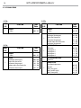
3.11 CONSTRUCTION OF THE DMX TERMINATION
The termination avoids the risk of DMX 512 signals being reflected back along the cable when they reach-
es the end of the line: under certain conditions and with certain cable lengths, this could cause them to
cancel the original signals.
The termination is prepared by soldering a 120Ω 1/4 W resistor between pins 2 and 3 of the 5-pin male XLR
connector, as shown in figure.
DMX - OUTPUT
XLR socket
DMX - INPUT
XLR plug
Pin1 : GND - Shield
Pin2 : - Negative
Pin3 : + Positive
Pin4 : N/C
Pin5 : N/C
Fig.7
Example:
5 pin XLR connector

STUDIOCOBPLUSUV
12
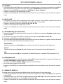
3.12 DMX CONTROL
1 Ch
MODE
FUNCTION DMX
Value
1 Ch
1
DIMMER
0~100% 000 - 255
2 Ch
MODE
FUNCTION DMX
Value
2 Ch
1
DIMMER
0~100% 000 - 255
2
STROBE
No function (shutter open)
Strobe effect slow to fast
No function (shutter open)
Random strobe effect slow to fast
No function (shutter open)
000 - 030
031 - 100
101 - 130
131 - 200
201 - 255
5 Ch
MODE
FUNCTION DMX
Value
5 Ch
1
DIMMER
0~100% 000 - 255
2
STROBE
No function (shutter open)
Strobe effect slow to fast
No function (shutter open)
Random strobe effect slow to fast
No function (shutter open)
000 - 030
031 - 100
101 - 130
131 - 200
201 - 255
3
AUTO PROGRAMM
NO Function
Auto program 1
Auto program 2
Auto program 3
Auto program 4
000 - 010
011 - 070
071 - 130
131 - 190
191 - 255
4
AUTO PROGRAMM SPEED
Slow to Fast 000 - 255
5
DIMMER SPEED
Preset from display menu
Mode off
Mode1 (fast speed)
Mode2 (middle speed)
Mode3 (slow speed)
000 - 051
052 - 101
102 - 152
153 - 203
204 - 255

13
STUDIOCOBPLUSUV
3.13 DIMMER
• To enter dimmer mode and choose to simulate different dimming curves, press the MENU button re-
peatedly until the display shows Dimmer Mode, then press the ENTER button.
• Press the MENU button repeatedly until Dimmer Mode shows, and press ENTER button to accept.
• Use the UP/DOWN buttons to select a dimmer curve Off - Dimmer1 - Dimmer2 - Dimmer3.
• Press ENTER button to accept.
• Press ENTER button to confirm the selection.
• Press the MENU button to go back or to meet the waiting time to exit from the setup menu automati-
cally.
3.14 BACK LIGHT
• To activate backlight display press the button MENU so many times until shows Back Light, and press the
ENTER button to confirm.
• Press the UP/DOWN buttons to select On - 10S - 20S - 30S. Press ENTER button to confirm the selection.
• Press the MENU button to go back or to meet the waiting time to exit from the setup menu automati-
cally.
3.15 FIXTURE INFORMATION
1. Press the MENU button so many times until shows Information, and then press ENTER button.
2. Use UP/DOWN button to select: Fixture Hours - Version - UID.
3. Press ENTER button to confirm the selection.
4. Press the MENU button to go back or to meet the waiting time to exit from the setup menu automati-
cally.
Fixture Hours
This option shows the user the amount of hours the STUDIOCOBPLUSUV has been in use throughout
its lifetime. Select Fixture Hours.
Version
This option shows the user the software version currently installed in the unit. Select Version.
UID
This option shows the RDM identification number
3.16 LED FREQUENCY
• To adjust the frequency of the LEDs, press the MENU button repeatedly until the display shows LED
Frequency, and then press the ENTER button.
• Select the frequency 600 Hz - 25 KHz using the UP/DOWN buttons.
• To confirm, press the ENTER key.
• Press the MENU button to go back or wait a few seconds to exit the setup menu.
3.17 FAN MODE
To set the rotation speed of the fans refer to the following guide:
• Press the MENU key repeatedly until the display shows Fan Mode, then press the button ENTER.
• Select by pressing UP/DOWN one of the following options: Auto - High. It is possible choose the speed of
rotation of the fans from: fast High and automatic Auto.
• Press the MENU button to go back or wait a few seconds to exit the setup menu.

STUDIOCOBPLUSUV
14
3.18 KEY LOCK
Enter the Key Lock mode to select whether the access password is on or off.
• Press the button MODE so many times until show Key Lock and press the button ENTER to confirm.
• Use UP/DOWN button to select: ON or OFF.
• Press ENTER button to confirm the selection.
When the fixture is set as pass ON, after 30 seconds or turn on the fixture next time, the fixture will need
an access password to enter the display menu control.
NOTE - The factory access password is UP + DOWN + UP + DOWN (press ENTER to confirm the access).
3.19 FACTORY RELOAD
Select this function to reset the unit to factory settings:
• Press the ENTER button to access the main menu.
• Press the UP/DOWN button to scroll the menu, select the Advanced icon, then press the ENTER button
to enter the next menu.
• Press the UP/DOWN button to scroll through the menu, select Factory Reload and press the ENTER button
to enter the next menu.
• Press the UP/DOWN button to select YES or NO, then press the ENTER button to confirm.
3.20 RDM - Remote Device Management
With this function you can call up various submenus via RDM.
This device is RDM ready. RDM stands for “Remote Device Management” and makes remote control of
devices connected to the DMX-bus possible. Manual settings like adjusting the DMX starting address are
no longer needed. This is especially useful when the device is installed in a remote area. RDM is integrated
in DMX without influencing the connections. The RDM-data is transmitted via the standard XLR-poles 1
and 2 – new DMX-cables are not necessary. RDM ready and conventional DMX devices can be operated
in one DMX line. The RDM protocol sends own packages in the DMX512 data feed and does not influence
conventional devices. If DMX splitters are used and RDM control is to be used, these splitters must sup-
port RDM. The number and type of RDM parameters depend on the RDM controller (not included) is used.

15
STUDIOCOBPLUSUV
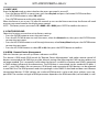
- 4 - MAINTENANCE
4.1 MAINTENANCE AND CLEANING THE UNIT
• Make sure the area below the installation place is free from unwanted persons during setup.
• Switch off the unit, unplug the main cable and wait until the unit has cooled down.
• All screws used for installing the device and any of its parts should be tightly fastened and should not
be corroded.
• Housings, fixations and installation spots (ceiling, trusses, suspensions) should be totally free from any
deformation.
• The main cables must be in impeccable condition and should be replaced immediately even when a
small problem is detected.
• It is recommended to clean the front at regular intervals, from impurities caused by dust, smoke, or
other particles to ensure that the light is radiated at maximum brightness. For cleaning, disconnect the
main plug from the socket. Use a soft, clean cloth moistened with a mild detergent. Then carefully wipe
the part dry. For cleaning other housing parts use only a soft, clean cloth. Never use a liquid, it might
penetrate the unit and cause damage to it.
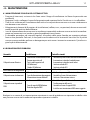
4.2 TROUBLESHOOTING
Problems Possible causes Checks and remedies
Fixture does not light up
• No mains supply
• Dimmer fader set to 0
• All color faders set to 0
• Faulty LED
• Faulty LED board
• Check the power supply voltage
• Increase the value of the dimmer channels
• Increase the value of the color channels
• Replace the LED board
• Replace the LED board
General low light intensity
• Dirty lens assembly • Clean the fixture regularly
Fixture does not power up
• No power
• Loose or damaged power cord
• Faulty internal power supply
• Check for power on power outlet
• Check power cord
• Replace internal power supply
Fixture does not respond to DMX
• Wrong DMX addressing
• Damaged DMX cables
• Bouncing signals
• Check control panel and unit addressing
• Check DMX cables
• Install terminator as suggested
Contact an authorized service center in case of technical problems or not reported in the table can not be
resolved by the procedure given in the table.

STUDIOCOBPLUSUV
2
Music & Lights S.r.l. si riserva ogni diritto di elaborazione in qualsiasi forma delle presenti istruzioni per l’uso.
La riproduzione - anche parziale - per propri scopi commerciali è vietata.
Al fine di migliorare la qualità dei prodotti, la Music&Lights S.r.l. si riserva la facoltà di modificare, in
qualunque momento e senza preavviso, le specifiche menzionate nel presente manuale di istruzioni.
Tutte le revisioni e gli aggiornamenti sono disponibili nella sezione 'Manuali' sul sito www.musiclights.it

3
STUDIOCOBPLUSUV
• STUDIOCOBPLUSUV
• Staffa di fissaggio
• Cavo di alimentazione
• Manuale utente
Contenuto dell'imballo:
INDICE
Sicurezza
Avvertenze generali
Attenzioni e precauzioni per l’installazione
1 Introduzione
1. 1 Descrizione
1. 2 Specifiche tecniche
1. 3 Elementi di comando e di collegamento
2 Installazione
2. 1 Montaggio
3 Funzioni e impostazioni
3. 1 Funzionamento
3. 2 Impostazione base
3. 3 Struttura menu
3. 4 Modalità automatica
3. 5 Modalità statica
3. 6 Modalità preset di bianco
3. 7 Modalità manuale
3. 8 Modalità Master/Slave
3. 7 Collegamento
3. 8 Modalità DMX
3. 9 Indirizzamento DMX
3. 10 Collegamenti della linea DMX
3. 11 Costruzione del terminatore DMX
3. 12 Canali DMX
3. 13 Dimmer
3. 14 Back Light
3. 15 Informazioni sul dispositivo
3. 16 Frequenza LED
3. 17 Modalità ventola
3. 18 KeyLock
3. 19 Factory Reset
3. 20 RDM
4 Manutenzione
4. 1 Manutenzione e pulizia del sistema ottico
4. 2 Risoluzione dei problemi
4
4
5
5
7
8
9
9
10
11
11
12
12
12
12
12
12
13
13
14
15
15
15
15
15
16
16
16
17
17

STUDIOCOBPLUSUV
4
ATTENZIONE! Prima di effettuare qualsiasi operazione con l’unità, leggere con attenzione
questo manuale e conservarlo accuratamente per riferimenti futuri. Contiene informazioni
importanti riguardo l’installazione, l’uso e la manutenzione dell’unità.
SICUREZZA
Avvertenze generali
• I prodotti a cui questo manuale si riferisce sono conformi alle Direttive della Comunità Europea e per-
tanto recano la sigla .
• Il dispositivo funziona con pericolosa tensione di rete 230V~. Non intervenire mai al suo interno al di
fuori delle operazioni descritte nel presente manuale; esiste il pericolo di una scarica elettrica.
• È obbligatorio effettuare il collegamento ad un impianto di alimentazione dotato di un’efficiente messa
a terra (apparecchio di Classe I secondo norma EN 60598-1). Si raccomanda, inoltre, di proteggere le
linee di alimentazione delle unità dai contatti indiretti e/o cortocircuiti verso massa tramite l’uso di
interruttori differenziali opportunamente dimensionati.
• Le operazioni di collegamento alla rete di distribuzione dell’energia elettrica devono essere effettuate
da un installatore elettrico qualificato. Verificare che frequenza e tensione della rete corrispondono alla
frequenza ed alla tensione per cui l’unità è predisposta, indicate sulla targhetta dei dati elettrici.
• L’unità non per uso domestico, solo per uso professionale.
• Evitare di utilizzare l’unità:
- in luoghi soggetti a vibrazioni, o a possibili urti;
- in luoghi a temperatura superiore ai 40°C.
• Evitare che nell’unità penetrino liquidi infiammabili, acqua o oggetti metallici.
• Non smontare e non apportare modifiche all’unità.
• Tutti gli interventi devono essere sempre e solo effettuati da personale tecnico qualificato. Rivolgersi al
più vicino centro di assistenza tecnica autorizzato.
• Se si desidera eliminare il dispositivo definitivamente, consegnarlo
per lo smaltimento ad un’istituzione locale per il riciclaggio.
Attenzioni e precauzioni per l’installazione
• Se il dispositivo dovesse trovarsi ad operare in condizioni differenti da quelle descritte nel presente
manuale, potrebbero verificarsi dei danni; in tal caso la garanzia verrebbe a decadere. Inoltre, ogni altra
operazione potrebbe provocare cortocircuiti, incendi, scosse elettriche, rotture etc.
• Prima di iniziare qualsiasi operazione di manutenzione o pulizia sull’unità togliere la tensione dalla rete
di alimentazione.
• È assolutamente necessario proteggere l’unità per mezzo di una fune di sicurezza. Nell’eseguire qual-
siasi intervento attenersi scrupolosamente a tutte le normative (in materia di sicurezza) vigenti nel
paese di utilizzo.
• Installare l’unità in un luogo ben ventilato.
• Mantenere i materiali infiammabili ad una distanza di sicurezza dall’unità.
• I filtri, le lenti o gli schermi ultravioletti se danneggiati possono limitare la loro efficienza.
• I LED devono essere sostituiti se danneggiati o termicamente deformati.
• Non guardare direttamente il fascio luminoso. Tenete presente che i veloci cambi di luce possono pro-
vocare attacchi d’epilessia presso persone fotosensibili o epilettiche.
• Non toccare l’alloggiamento del prodotto quando è in funzione perché potrebbe essere molto caldo.
La pagina si sta caricando...
La pagina si sta caricando...
La pagina si sta caricando...
La pagina si sta caricando...
La pagina si sta caricando...
La pagina si sta caricando...
La pagina si sta caricando...
La pagina si sta caricando...
La pagina si sta caricando...
La pagina si sta caricando...
La pagina si sta caricando...
La pagina si sta caricando...
La pagina si sta caricando...
La pagina si sta caricando...
La pagina si sta caricando...
La pagina si sta caricando...
-
 1
1
-
 2
2
-
 3
3
-
 4
4
-
 5
5
-
 6
6
-
 7
7
-
 8
8
-
 9
9
-
 10
10
-
 11
11
-
 12
12
-
 13
13
-
 14
14
-
 15
15
-
 16
16
-
 17
17
-
 18
18
-
 19
19
-
 20
20
-
 21
21
-
 22
22
-
 23
23
-
 24
24
-
 25
25
-
 26
26
-
 27
27
-
 28
28
-
 29
29
-
 30
30
-
 31
31
-
 32
32
-
 33
33
-
 34
34
-
 35
35
-
 36
36


ProLights STUDIOCOBPLUSUV Manuale utente
- Categoria
- Stroboscopi
- Tipo
- Manuale utente
in altre lingue
Documenti correlati
-
ProLights DISPLAYCOBTRWDFC Manuale utente
-
-
-
-
-
-
-
ProLights 150W IP65 rated full colour COB LED Par Manuale utente
-