
MANUAL
Simrad AI50
Class B Transceiver
988-0168-001 May07 English


MANUAL
Simrad AI50
Class B Transceiver
988-0168-002 Iss.2.0 English

The technical data, information and illustrations contained in this publication were to the best of our knowledge correct
at the time of going to print. We reserve the right to change specifi cations, equipment, installation and maintenance
instructions without notice as part of our policy of continuous development and improvement.
No part of this publication may be reproduced, stored in a retrieval system or transmitted in any form, electronic or
otherwise, without prior permission from Simrad Ltd.
No liability can be accepted for any inaccuracies or omissions in the publication, although every care has been taken to
make it as complete and accurate as possible.
© 2007 Navico
988-0168-001 Iss.2.0 May 07 WP

Contents
V
AIS50 CLASS B TRANCEIVER
CONTENTS
1 INTRODUCTION
1.1 General Overview 9
1.2 About this manual 10
1.3 SimNet/NMEA2000 Network System 10
2 INSTALLATION
2.1 General 11
2.2 Panel Mounting 11
2.3 Bracket Mounting 12
2.4 GPS Antenna 12
2.5 VHF Antenna 13
2.6 Power/Data Cable 15
2.7 SimNet Cable 15
2.8 SD card (Not supplied) 16
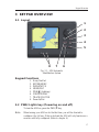
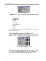
3 KEYPAD OVERVIEW
3.1 Layout 17
3.2 PWR/Lights key (Powering on and off) 17
3.3 Navigation Keys 18
3.3.1 Display Mode 18
3.3.2 Menu Mode 18
3.3.3 Data Entry Mode 18
3.4 Zoom Keys 18
3.5 ENTER/MENU 18
3.6 INFO/STATUS 19
3.7 TRACK/CLR TRK 19
3.8 HOME/DSC 19
3.9 VIEW/DISPLAY 19
3.10 PWR/ (Backlight adjustment) 19
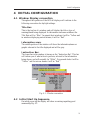
4 INITIAL CONFIGURATION
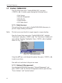
4.1 Window Display convention 21
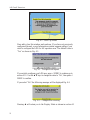
4.2 Initial Start Up Sequence 21
4.3 Ship Confi guration Procedure 23
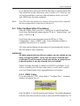
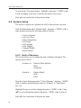
4.3.1 MMSI Entry 23
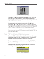
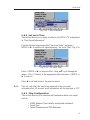
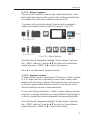
4.3.2 Vessel Type Entry 25
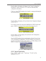
4.3.3 Vessel Dimensions & GPS Reference 26

AIS Class B Transceiver
VI
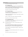
4.3.4 Call Sign Entry 27
4.3.5 Vessel Name Entry 28
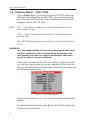
5 MENU MODE
5.1 General 29
5.2 Display Mode settings 29
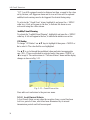
5.2.1 Coastline Detail 29
5.2.2 Tracking Offset 30
5.2.3 Display Offset 30
5.2.4 Show Range Rings 31
5.3 Display Settings 31
5.3.1 Display Brightness 31
5.3.2 Keypad Brightness 32
5.3.3 Keypad Colour 32
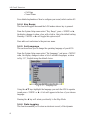
5.3.4 Display Palette 32
5.4 Favourites List 33
5.4.1 Add an Entry 33
5.4.2 Edit an Entry 34
5.4.3 Delete an Entry 35
5.5 Alarm Setup 35
5.5.1 Collision Alarm 36
5.5.1.1 CPA/TCPA 36
5.5.1.2 Guard Zone 37
5.5.2 Lost Vessel Alarm 38
5.5.3 Favourites Alarm 39
5.6 System Setup 40
5.6.1 Units of Measure 40
5.6.2 Set Local Time 41
5.6.3 Ship Confi guration 41
5.6.4 Key Beeps 42
5.6.5 Set Language 42
5.6.6 Data Logging 42
5.6.6.1 Enabling 43
5.6.6.2 Disabling 44
5.6.6.3 Playback Log 44
5.6.7 Transmit Enable 45
5.6.8 Reset Options 45
5.7 SimNet/NMEA2000 45
5.7.1 Data Sources 46
5.7.2 Network Management 46

Contents
VII
5.7.2.1 Device Instance 46
5.7.2.2 System Instance 47
5.7.3 Network List 47
5.7.4 Remote Enable 48
5.7.4 DSC Radio Select 48
5.8 Product Info 48
6 AIS MAP MODE
6.1 General 51
6.2 Vessel Icon Detail 51
6.3 Range Rings/ Range Info 51
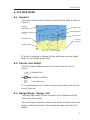
6.4 Point Of View 52
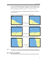
6.5 Coast Line Detail 54
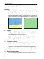
6.6 Cursor 54
6.7 Transmit Legend 54
6.8 Vessel Information 55
6.8.1 Own Vessel 55
6.8.2 Other Vessel’s Info (Reduced list) 55
6.8.3 Other Vessel (Full list) 56
6.8.4 Other Vessel (Minimal list) 56
6.9 General Rules for Vessel Information 57
6.10 Making a DSC Call (in map mode) 57
6.11 Text Mode 58
6.11.1 Changing the Sort Order 59
6.12 Making a DSC Call (in text mode) 59
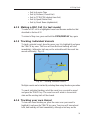
6.13 Tracking Individual Vessels 59
6.14 Tracking your own Vessel 60
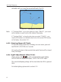
6.15 Clearing Down All Trails 60
6.16 Light Adjustment (Short Cut) 61
7 ALARMS
7.1 General 63
7.2 Collision Alarm – CPA/TCPA 64
7.3 Collision Alarm – Lost Vessel 65
7.4 Collision Alarm – Guard Zone 66
7.5 BIIT Alarm 66
7.6 Lost Vessel Alarm 67
7.7 Favourites Alarm 67
7.8 Loss Of Compass Heading Data 68
7.9 Safety Message Alarm 69

AIS Class B Transceiver
VIII
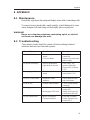
8 APPENDIX
8.1 Maintenance 71
8.2 Troubleshooting 71
8.3 Accessories 72
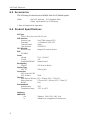
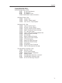
8.4 Product Specifi cations 72
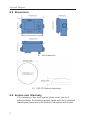
8.5 Dimensions 74
8.6 Service and Warranty 74
8.7 Declaration of Conformity (EU) 75

Introduction
9
1 INTRODUCTION
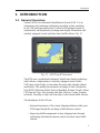
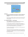
1.1 General Overview
Simrad’s AI50 is an Automatic Identifi cation System (AIS). It is an
autonomous and continuous information reporting system, operating
in the VHF maritime mobile band. It allows AIS equipped vessels to
automatically and dynamically exchange and display information with
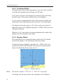
similarly equipped vessels and shore based traffi c stations. Fig. 1.1
The AI50 uses a sophisticated automatic digital time sharing technology
which allows a large number of similarly equipped vessels within
VHF range of each other, to time share the same radio channel without
interference. This enables the automatic exchange of static information
like; MMSI (Maritime Mobile Service Identifi er) Number, Vessel’s Name,
Call Sign and Type. Also dynamic data like; Position, Course, Distance
and more, from ship to ship, and from ship to shore based traffi c stations.
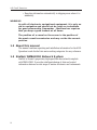
The advantages of the AI50 are:
Increased awareness of the current shipping situation within your
VHF range through the exchange of data between vessels.
Improving traffi c management in busy shipping lanes through
exchanging information between vessels and shore based traffi c
stations.
•
•
Fig. 1.1 - AI50 Class B Transceiver

AIS Class B Transceiver
10
Reporting information automatically in shipping areas where it is
mandatory.
WARNING
As with all electronic navigational equipment, it is only an
aid to navigation and should not be used as a substitute
for good seamanship. Remember - Maritime law requires
that you keep a good lookout at all times.
The position of a vessel on the screen is the position of
the most recent transmission and may not be the current
position.
1.2 About this manual
The manual combines operating and installation information for the AI50.
Operation is sub-divided into main working categories for easy reference.
1.3 SimNet/NMEA2000 Network System
SimNet is Simrad’s proprietary high speed data bus network complete
with NMEA2000. It provides intelligent sharing of data and control
information between a wide range of marine electronics and instruments.
•

Installation
11
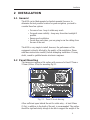
2 INSTALLATION
2.1 General
The AI50 can be fl ush mounted or bracket mounted, however, to
determine the best possible location for good navigation, you need to
consider these few options:
For ease of use - keep it within easy reach
For good screen visibility - keep away from direct sunlight if
possible
Ensure good ventilation
Decide how and where, you are going to run the cabling from
the rear of the unit.
The AI50 is very simple to install, however, the performance of the
equipment is directly affected by the quality of the installation. Please
read these instructions carefully before attempting installation. If in any
doubt, consult a qualifi ed marine electronics engineer.
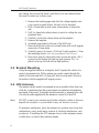
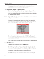
2.2 Panel Mounting
The transceiver requires a flat surface with an area of at least 172mm x
115mm (6.8in x 4.5in) for mounting Fig 2.1.
Allow sufficient space behind the unit for cable entry – at least 50mm
(2.0in), in addition to the depth of the unit, is recommended. The surface
should be rigid and sturdy enough to be able to support the weight of the
•
•
•
•
Fig. 2.1 – Panel Cut-out drawing

AIS Class B Transceiver
12
unit, taking into account the shock loads likely to be encountered when
the vessel is under way in heavy seas.
Remove the backing paper and stick the cutting template onto
your console or panel where the unit is to be mounted.
Drill a 2.5mm hole in each corner, where shown, to fasten the
unit.
Drill 8 x 6mm holes where shown to assist in cutting the case
peripheral hole.
Carefully cut the hole where shown on the template.
Remove the template.
Assemble case gasket to the rear of the AI50 unit.
Place the AI50 unit in the cut-out and fasten with 4 self tapping
screws into 2.5mm holes.
Carefully remove 4 corners, (3 left and 3 right supplied, ), from
the moulding rosette.
(Note: they are numbered 1 and 2 on rear)
Place the 4 snap fit, removable corner covers into place. (No.1
is placed in the bottom left and top right position, No. 2 is
placed in the top left and bottom right position.
2.3 Bracket Mounting
Using the supplied bracket as a template, hold it against the surface it is
going to be mounted on. With a marker pen, make a mark through the
centre of the holes and drill a 3.5mm pilot hole on each mark. Secure to
the surface with the supplied self tapping screws.
2.4 GPS Antenna
The antenna, ideally needs to be mounted as low as possible with a clear view
of the sky to minimise errors due to movement over and above the transitory
movement of the vessel. It can either be deck mounted, or mounted onto a rail.
Use only the cable supplied with the antenna to connect it to the AI50.
Note DO NOT connect your antenna using further extension cables as this may
degrade the reception to a point where it may not function correctly.
To minimize interference, place the antenna in a position away from steel
constructions, wires, metal masts, sources of electrical interference, such
as radar etc. If installing the GPS antenna close to other antennas, mount
it either above or below their radiation beams.
1.
2.
3.
4.
5.
6.
7.
8.
9.

Installation
13
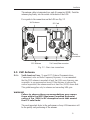
The antenna cable is terminated in a push fit connector (SMB). Push the
antenna plug firmly into the socket on the back of the AI50.
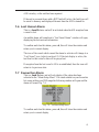
For a guide to the connections on the AI50 see Fig. 2.2
2.5 VHF Antenna
Note North American Users - To meet FCC (Federal Communications
Commission) rules on Radio Frequency Exposure, it is recommended
that the VHF antenna is mounted at least 3m (10ft) away from any area
accessible to any personnel on board. If this distance is achieved by
vertical separation, the antenna must be at least 5m (16.5ft) above deck.
This guideline applies only to antennas not exceeding 3dBi gain.
WARNING
Failure to observe these recommendations may expose
those within the MPE (Maximum Permitted Exposure)
radius of 3m (10ft) to RF absorption levels that exceed
the FCC safe limits.
The most important factor in the performance of any AIS transceiver will
be the quality and positioning of the antenna.
VHF Antenna
GPS Antenna
12v Power/Data connector
SImNet
SD Card
connectors
Fig. 2.2 - Rear view connections

AIS Class B Transceiver
14
As the range of VHF signals are governed by line of sight, the antenna should
be placed as high as possible, while remaining clear of any metallic objects.
Long whip antennae are generally recommended for larger boats, although the
most popular antennae for marine use is 1m (3ft 3in) long. On sailboats these
are usually mounted on the masthead, where the length of the antenna keeps it
clear from the navigation lights and wind vanes. This type of antenna can also
be mounted on the cockpit roof or powerboat garages.
For maximum range, it is recommended that a VHF antenna specifically
tuned for use with an AIS is used, and mounted away from the standard
VHF antenna. Vertical separation is preferred, but where this is not
practical, at least 5 metre horizontal spacing is recommended
WARNING
The antenna coaxial cable and any connectors used must
be rated at 50Ω. Under no circumstances should standard
domestic TV cable and connectors be used. Incorrectly
rated cabling and connectors could result in power not
reaching the antenna, but also power could be reflected
back into the AI50 unit, damaging it in the process.
The quality of any connections and integrity of the cable will directly affect
the performance of the radio. Poor soldering or corrosion of the terminals
can impair performance. We recommend that screw or crimp terminal
type connectors are not used for any through deck fittings - a good quality
waterproof solder terminal connector will be less susceptible to poor
connection due to corrosion of the contacts.
To ensure the best performance of the radio, the antenna cable should be
routed where it is least likely to interfere with, or receive interference
from other electronic equipment, such as echo sounder transducer cables
and high current carrying cables.
The antenna cable should terminate in a standard marine PL259 plug
fitting. Connect the antenna plug to the socket on the back of the AI50
and screw the retaining collar down Fig. 2.3.
Note To avoid possible water damage to the transceiver, it is recommended that all
cables are looped to provide a drip path.

Installation
15
2.6 Power/Data Cable
Power cable - The electrical installation is quite straightforward - push the
connector end of the supplied Power/Data cable fi rmly into the socket on
the rear of the unit. The Power cable has two wires, one red and one black.
Connect the red cable to +12V via a 2Amp fuse, and the black cable to 0V.
Data cable - The data cable is used for connectivity to AIS enabled chart
plotters with NMEA0183 interface. The Data cable is screened and has
four wires. For connection data refer to the following table Fig.2.4.
Signal Colour Comment
Out +ve Orange
Out -ve Blue
In +ve Yellow Not Used
In -ve Green Not Used
0v Screen
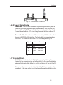
2.7 SimNet Cable
The AI50 is connected to the SimNet databus using the cable supplied.
Ensure that the connector on the end of the cable is in the correct orientation
and press firmly into either of the two sockets on the rear of the unit. Fig.2.2.
The spare socket can be used to daisy chain SimNet to another item of
equipment. If the spare socket is not used insert the supplied blanking plug.
Fig. 2.4 - NMEA0183 connectionsFig. 2.4 - NMEA0183 connections
Fig 2.3 - VHF Antenna connection

AIS Class B Transceiver
16
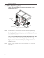
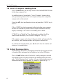
2.8 SD card (Not supplied)
The SD card slot is situated on the reverse of the unit under a water
resistant cover, Fig. 2.5.
Note DO NOT insert or remove the SD card while the AI50 is powered up.
Locate and undo the two retaining screws, and carefully remove the cover
to reveal the SD card slot.
With the SD card contact side down, place under the shroud and slide fi rmly
into place, making sure the card is sitting squarely and not at an angle.
Replace the cover and screw back into place, making sure not to over
tighten the screws.
Note The use of high speed SD cards is not recommended. Use Class 1 SD
cards only.
Access Cover
Retaining Screws
Shroud
Fig. 2.5 - SD Card Access Cover

Keypad Overview
17
3 KEYPAD OVERVIEW
3.1 Layout
Keypad Functions
8-way NavPad
ENTER/MENU
INFO/STATUS
HOME/DSC
PWR/ (Lighting)
VIEW/DISPLAY
TRACK/CLR TRK
Zoom In/Out
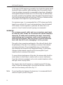
3.2 PWR/Lights key (Powering on and off)
To turn the AI50 on, press the PWR/ key.
Note When turning your AI50 on for the fi rst time, you will be directed to
confi gure it for full use. If this is declined the AI50 will only function as a
receiver until fully confi gured. (Refer to chapter 4).
1.
2.
3.
4.
5.
6.
7.
8.
1
76
5
4
3
2
8
Fig. 3.1 - AI50 Automatic
Identifi cation System

AIS Class B Transceiver
18
To turn the AI50 off, press and hold the PWR/ key for a few seconds.
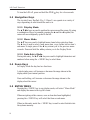
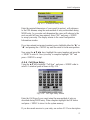
3.3 Navigation Keys
The circular 8-way NavPad, (Fig. 3.1 Item 1) can operate in a variety of
ways depending on which mode the unit is in.
3.3.1 Display Mode
The ▲▼◄► keys are used to position the cursor around the screen. By using
a combination of keys, for example, pressing the ▲ and the ◄ together, the
cursor will move diagonally up and to the left.
3.3.2 Menu Mode
The ▲▼ keys are used to highlight menu items before selecting them.
The ► key is used to select a new menu item, or go further into an item’s
sub menu. A single press of the ◄ key returns you to the previous menu
or mode. Press and hold the ◄ key returns you to the Display Mode
3.3.3 Data Entry Mode
During data entry, the ▲▼◄► keys are used to highlight characters and
numbers before using the MENU key to select them.
3.4 Zoom Keys
In Display Mode the key has two functions:
A short single press, will increase or decrease the range shown in the
display about your current position.
Press and holding, will increase or decrease the range shown in the
display about the cursor.
3.5 ENTER/MENU
Pressing the MENU key in any display mode, will select “Menu Mode”
and display the menu in the top left corner.
When navigating within a menu, once an item has been highlighted,
pressing the MENU key will select that item or sub menu.
When in data entry mode the MENU key is used to enter that data into
the systems memory.

Keypad Overview
19
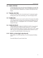
3.6 INFO/STATUS
A short press allows you to view the received information of a vessel that
has been highlighted using the cursor. Press and holding the Info key will
show your own vessel’s information in a column on the right side of the
display.
3.7 TRACK/CLR TRK
The AI50 can show the track of a selected vessel. A single press toggles
tracking mode on/off. Press and holding, will clear all displayed tracks.
3.8 HOME/DSC
Resets the view and your own vessel’s position to the centre of the display
or the offset position if activated. Press and holding the HOME/DSC key
initiates a DSC call, to a highlighted vessel, via an installed, compatible
SimNet VHF radio.
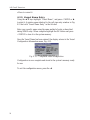
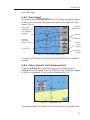
3.9 VIEW/DISPLAY
Toggle between views (HEADUP, NORTHUP, COGUP). Press and hold
to access Text Mode in which the map is replaced by a list of target
vessels and their details. While in Text Mode, short presses of the “VIEW/
TEXT” key will cycle through the predefined order in which the vessels
are sorted. Press and hold again to restore map view.
3.10 PWR/ (Backlight adjustment)
Short presses of the PWR/Lights key will cycle through preset lighting
levels.
Press and holding will power the unit down.

La pagina si sta caricando...
La pagina si sta caricando...
La pagina si sta caricando...
La pagina si sta caricando...
La pagina si sta caricando...
La pagina si sta caricando...
La pagina si sta caricando...
La pagina si sta caricando...
La pagina si sta caricando...
La pagina si sta caricando...
La pagina si sta caricando...
La pagina si sta caricando...
La pagina si sta caricando...
La pagina si sta caricando...
La pagina si sta caricando...
La pagina si sta caricando...
La pagina si sta caricando...
La pagina si sta caricando...
La pagina si sta caricando...
La pagina si sta caricando...
La pagina si sta caricando...
La pagina si sta caricando...
La pagina si sta caricando...
La pagina si sta caricando...
La pagina si sta caricando...
La pagina si sta caricando...
La pagina si sta caricando...
La pagina si sta caricando...
La pagina si sta caricando...
La pagina si sta caricando...
La pagina si sta caricando...
La pagina si sta caricando...
La pagina si sta caricando...
La pagina si sta caricando...
La pagina si sta caricando...
La pagina si sta caricando...
La pagina si sta caricando...
La pagina si sta caricando...
La pagina si sta caricando...
La pagina si sta caricando...
La pagina si sta caricando...
La pagina si sta caricando...
La pagina si sta caricando...
La pagina si sta caricando...
La pagina si sta caricando...
La pagina si sta caricando...
La pagina si sta caricando...
La pagina si sta caricando...
La pagina si sta caricando...
La pagina si sta caricando...
La pagina si sta caricando...
La pagina si sta caricando...
La pagina si sta caricando...
La pagina si sta caricando...
-
 1
1
-
 2
2
-
 3
3
-
 4
4
-
 5
5
-
 6
6
-
 7
7
-
 8
8
-
 9
9
-
 10
10
-
 11
11
-
 12
12
-
 13
13
-
 14
14
-
 15
15
-
 16
16
-
 17
17
-
 18
18
-
 19
19
-
 20
20
-
 21
21
-
 22
22
-
 23
23
-
 24
24
-
 25
25
-
 26
26
-
 27
27
-
 28
28
-
 29
29
-
 30
30
-
 31
31
-
 32
32
-
 33
33
-
 34
34
-
 35
35
-
 36
36
-
 37
37
-
 38
38
-
 39
39
-
 40
40
-
 41
41
-
 42
42
-
 43
43
-
 44
44
-
 45
45
-
 46
46
-
 47
47
-
 48
48
-
 49
49
-
 50
50
-
 51
51
-
 52
52
-
 53
53
-
 54
54
-
 55
55
-
 56
56
-
 57
57
-
 58
58
-
 59
59
-
 60
60
-
 61
61
-
 62
62
-
 63
63
-
 64
64
-
 65
65
-
 66
66
-
 67
67
-
 68
68
-
 69
69
-
 70
70
-
 71
71
-
 72
72
-
 73
73
-
 74
74


Simrad AI50 Manuale utente
- Tipo
- Manuale utente
- Questo manuale è adatto anche per
in altre lingue
- English: Simrad AI50 User manual