Shure R3 Manuale del proprietario
- Categoria
- Microfoni
- Tipo
- Manuale del proprietario

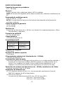
IMPORTANT!
The Shure UHF MK2 Series wireless systems meet the essential requirements of the
European R&TTE Directive 99/5/E and are eligible to bear the CE marking.
Shure UHF components bearing the MK2 insignia are compatible with other Shure UHF
Series wireless systems, but ARE NOT interchangeable with UHF Series components;
i.e., a UHF MK2 Transmitter cannot be used with a U4 Receiver that lacks the MK2 insig-
nia.
SPECIFICATIONS 2. . . . . . . . . . . . . . . . . . . . . . . . . . . . . . . . . . . . . . . . . . . . . . . . .
UHF WIRELESS SYSTEM COMPATIBILITY GUIDE 7. . . . . . . . . . . . . . . . . . .
MASTER LIST 43. . . . . . . . . . . . . . . . . . . . . . . . . . . . . . . . . . . . . . . . . . . . . . . . . . .
CARACTÉRISTIQUES TECHNIQUES 11. . . . . . . . . . . . . . . . . . . . . . . . . . . . . .
GUIDE DE COMPATIBILITÉ DU SYSTÈME UHF SANS FIL 17. . . . . . . . . . . .
LISTE MAÎTRESSE 43. . . . . . . . . . . . . . . . . . . . . . . . . . . . . . . . . . . . . . . . . . . . . . .
SPEZIFIKATIONEN 19. . . . . . . . . . . . . . . . . . . . . . . . . . . . . . . . . . . . . . . . . . . . . . .
KOMPATIBILITÄTSLEITSFADEN FÜR UHF–R3–DRAHTLOSESSYSTEME 25. .
HAUPTLISTE 47. . . . . . . . . . . . . . . . . . . . . . . . . . . . . . . . . . . . . . . . . . . . . . . . . . . .
ESPECIFICACIONES 27. . . . . . . . . . . . . . . . . . . . . . . . . . . . . . . . . . . . . . . . . . . . .
GUÍA DE COMPATIBILIDAD DE SISTEMAS INALÁMBRICOS UHF R3 33. .
LISTA MAESTRA 47. . . . . . . . . . . . . . . . . . . . . . . . . . . . . . . . . . . . . . . . . . . . . . . . .
DATI TECNICI 35. . . . . . . . . . . . . . . . . . . . . . . . . . . . . . . . . . . . . . . . . . . . . . . . . . .
GUIDA ALLA COMPATIBILITÀ DEL RADIOSISTEMA UHF R3 41. . . . . . . . . .
L’ELENCO PRINCIPALE 47. . . . . . . . . . . . . . . . . . . . . . . . . . . . . . . . . . . . . . . . . .
UHF MK2 Wireless System
27A8755 (AF)
2001, Shure Incorporated
Printed in U.S.A.
USER GUIDE SUPPLEMENT
BEDIENUNGSANLEITUNG ANHANG
R3 (774 – 782 MHz)
RENSEIGNEMENT SUPPLÉMENTAIRES
INFORMACION ADICIONAL
INFORMAZIONI SUPPLEMENTARI

2
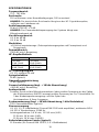
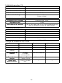
SPECIFICATIONS
RF Carrier Frequency Range
774 – 782 MHz
Working Range
U1, U2: 152.4 m, minimum, under typical conditions; 487.6 m line of sight
NOTE: Actual working range depends on RF signal absorption, reflection and interference
Audio Frequency Response
50 to 15,000 Hz, ±2 dB. NOTE: Overall system frequency response depends on the
microphone element
Gain Adjustment Range
U1: 0 to 40 dB
U2: 0 to 26 dB
Modulation
±18 kHz deviation compressor-expander system with pre-and de-emphasis
RF Power Output
U1, U2: 10 mW maximum
Dynamic Range
>102 dB, A-weighted
RF Sensitivity
U4S U4D
–110 dBm
12 dB SINAD
–107 dBm
12 dB SINAD
–105 dBm
30 dB SINAD
–102 dBm
30 dB SINAD
Image Rejection
90 dB typical
Spurious Rejection
75 dB typical
Ultimate Quieting (ref. ±18 kHz deviation)
>100 dB, A-weighted
Audio Polarity
Positive pressure on microphone diaphragm (or positive voltage applied to tip of
WA302 phone plug) produces positive voltage on pin 2 with respect to pin 3 of low
impedance output and the tip of the high impedance
1
/
4
-inch output
System Distortion (ref. ±18 kHz deviation, 1 kHz modulation)
0.3% Total Harmonic Distortion typical
Power Requirements
U1, U2: 1.5V AA alkaline battery (Duracell MN1500 recommended); Nicad optional
U4: 230 Vac , 50/60 Hz
Power Consumption:
U4S: 9.6 W min., 13.2 W max.
U4D: 12 W min.,16 W max.
UA845: 15 W min., 16 W max.
Battery Life (Typical)
U1, U2: 12 hours (with Duracell MN1500 1.5V AA alkaline battery)
Operating Temperature Range
-6° to +49° C
NOTE: Battery characteristics may limit this range

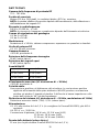
3
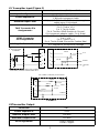
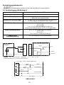
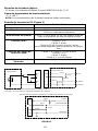
U1 Transmitter Input (Figure 1)
Connector:
4-pin miniature (TA4F) or LEMO
Input Configuration:
Unbalanced, active
Actual Impedance:
18 kΩ with lavalier microphone
1 MΩ with instrument cable
Maximum Input Level:
6 Vp–p (+7 dBV) for 1% THD at minimum gain
setting using 1 kHz signal.
TA4F Connector Pin
Assignments:
Pin 1: Tied to Ground
Pin 2: Tied to +5 V
Pin 3: Tied to Audio
Pin 4: Tied thru 20kΩ Resistor to Ground.
(On instrument adapter cable, Pin 4 floats)
LEMO Connector
Pin Assignments:
Pin 1: Tied to Pin 3 and 10 kΩ to Ground
Pin 2: +5V
Pin 3: Tied to Pin 1
Pin 4: Tied to Shield (Ground for Positive Bias)
Voltage for Remote Power:
+5 V supplied to microphone cartridge
27 pF
20K Ω
27 pF
+5 V
AUDIO
GROUN
D
U1 MIC JACK BOARD
2
1
4
500 Ω
500 Ω
MICROPHONE
ELEMENT
3
2
1
3
4
NOTE: LAVALIER MIC TIES PINS 3 AND 4
TOGETHER; GUITAR CABLE DOES NOT.
27 pF
499 Ω
499 Ω
3
27 pF
10K Ω
AUDIO
SHIELD
U1L (LEMO 4 PIN) MIC JACK BOARD
1
4
2
BIAS
FIGURE 1
U1Transmitter Output
Connector: SMC
Actual Impedance: 50 Ω
Nominal Output Level: +10 dBm
Maximum Output Level: +11 dBm
Pin Assignments: Shell = Ground
Center = Signal

4
U2 Transmitter Input
Input Configuration: Unbalanced, active
Actual Impedance: 20 kΩ
Maximum Input Level: 3 Vp–p (0.5 dBV) for 1% THD at minimum gain setting
using 1 kHz signal.
U2 Transmitter Output
Connector: SMC
Actual Impedance: 50 Ω
Nominal Output Level: +10 dBm
Maximum Output Level: +11 dBm
Pin Assignments: Shell = Ground
Center = Signal
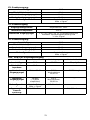
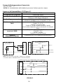
U4S and U4D Receiver Input
Connector: Antenna Power Input Network Interface
Connector Type: BNC IEC 320 25–Pin D
Actual Impedance: 50 Ω –– ––
Nominal Input
Level:
–95 to –30 dBm 230 VAC,
50/60 Hz
CMOS Logic
Maximum Input
Level:
+6 dBm
(–20 dBm
recommended)
254 VAC, 50/60 Hz ––
Pin Assignments: Shell = Ground
Center = Signal
IEC Standard ––
Voltage for
Remote Power:
12 Vdc, 150 mA
maximum
–– 5V, 700 mA max.
U4S and U4D Receiver Output
Connector: Monitor Power
Output
High Z
Audio
Low Z
Audio*
Network
Interface
Output
Configuration
:
Unbalanced
mono, 1/4 inch
–– Unbalance
d
Balanced See
Appendix
Actual
Impedance:
300 Ω –– 1 kΩ 30 Ω See
Appendix
Nominal
Input Level:
–– 230 VAC,
5A
–– –– CMOS
Logic
Pin
Assignments:
Tip = Hot
Ring = Hot
Sleeve = Gnd
IEC
Standard
Tip = Hot
Ring/
Sleeve =
Gnd
1 =
Ground
2 = Hot
3 = Hot
See
Appendix
Voltage/
Current/
Phantom
Power
Protection?
Yes –– Yes Yes 5V, 700 mA
resettable
polyfuse
*Output Level: Microphone Level = Line Level – 30 dB

5
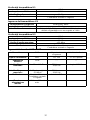
Overall Dimensions
U1: 92.2 mm L x 64.7 mm W x 24.2 mm D
U2/58:254 mm L x 50.8 mm Dia.
U2/BETA 58: 254 mm L x 53.2 mm Dia.
U2/87:228.6 mm x 49.2 mm Dia.
U2/BETA 87: 216 mm L x 50.8 mm Dia
U4S/U4D: 44.5 mm H x 482.6 mm W x 295.3 mm D
Net Weight
U1: 175.2 g without battery
U2/58, U2/BETA 58: 375.6 g without battery
U2/87, U2/BETA 87: 303.1 g without battery
U4S: 3.30 kg
U4D: 3.85 kg
Certification
The Shure UHF series wireless systems meet the essential requirements of the
European R&TTE Directive 99/5/EC and are eligible to carry the CE marking.
U1, U2: Conforms to European ETSI Standard EN 300 422 (Parts 1 and 2) and ETS
300445/A1.
U4, U4D: Conforms to European ETSI Standard EN 300 445/A1 and EN 60950.
THIS RADIO EQUIPMENT IS INTENDED FOR USE IN PROFESSIONAL
ENTERTAINMENT (CLASS I) AND SIMILAR APPLICATIONS.
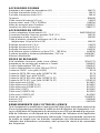
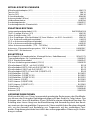
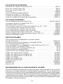
FURNISHED ACCESSORIES
Microphone Stand Adapter (U2) WA371. . . . . . . . . . . . . . . . . . . . . . . . . . . . . . . . . . . . . . .
Zipper Bag (U1) 26A13. . . . . . . . . . . . . . . . . . . . . . . . . . . . . . . . . . . . . . . . . . . . . . . . . . . . . .
Zipper Bag (U2) 26A14. . . . . . . . . . . . . . . . . . . . . . . . . . . . . . . . . . . . . . . . . . . . . . . . . . . . . .
Screwdriver 80A498. . . . . . . . . . . . . . . . . . . . . . . . . . . . . . . . . . . . . . . . . . . . . . . . . . . . . . . .
Coaxial Antenna Cable (2 ft) UA802. . . . . . . . . . . . . . . . . . . . . . . . . . . . . . . . . . . . . . . . . .
1/2 Wave Antenna UA820A. . . . . . . . . . . . . . . . . . . . . . . . . . . . . . . . . . . . . . . . . . . . . . . . . .
Transmitter Carrying Case 65A8257. . . . . . . . . . . . . . . . . . . . . . . . . . . . . . . . . . . . . . . . . . .
Carrying Case Insert 29B1577. . . . . . . . . . . . . . . . . . . . . . . . . . . . . . . . . . . . . . . . . . . . . . . .
OPTIONAL ACCESSORIES
Instrument Adapter Cable (U1) WA302. . . . . . . . . . . . . . . . . . . . . . . . . . . . . . . . . . . . . . . .
Instrument Adapter Cable w/ right angle 1/4” plug (U1) WA304. . . . . . . . . . . . . . . . . . .
TA4F Female 4-Pin Miniature Connector (U1) WA330. . . . . . . . . . . . . . . . . . . . . . . . . . .
In-Line Audio Switch (U1) WA360. . . . . . . . . . . . . . . . . . . . . . . . . . . . . . . . . . . . . . . . . . . . .
1.8 Meter (6 ft) Receiver-Mixer Cable (
1
/
4
” phone to XLR) WA410. . . . . . . . . . . . . . . . .
7.6 Meter (25 ft) Antenna Extension Cable UA825. . . . . . . . . . . . . . . . . . . . . . . . . . . . . .
15.2 Meter (50 ft) Antenna Extension Cable UA850. . . . . . . . . . . . . . . . . . . . . . . . . . . . .
30.4 Meter (100 ft) Antenna Extension Cable UA8100. . . . . . . . . . . . . . . . . . . . . . . . . . .
In-Line Active Remote Antenna Kit (774 – 782 MHz) UA830D. . . . . . . . . . . . . . . . . . . .
Antenna/Power Distribution System, 230 Vac UA845MC. . . . . . . . . . . . . . . . . . . . . . . . .
Directional Antenna UA870MC. . . . . . . . . . . . . . . . . . . . . . . . . . . . . . . . . . . . . . . . . . . . . . .

6
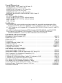
REPLACEMENT PARTS
Hardware Kit (screwdriver, mounting feet, cable clamps) 90VL1371. . . . . . . . . . . . . . .
Bulkhead Adapters for Front–Mounting Antennas 95A8647. . . . . . . . . . . . . . . . . . . . . . .
230 VAC Power Cord (Schuko mains connector) 95A8247. . . . . . . . . . . . . . . . . . . . . . . .
304 mm (12 in.) Daisy–Chain Power Cord (230 V) 95A8678. . . . . . . . . . . . . . . . . . . . . .
SM58
Cartridge with Grille (U2/58) R158. . . . . . . . . . . . . . . . . . . . . . . . . . . . . . . . . . . . .
BETA 58A Cartridge with Grille (U2/BETA 58) R179. . . . . . . . . . . . . . . . . . . . . . . . . . . . .
SM87 Cartridge with Grille (U2/87) R165. . . . . . . . . . . . . . . . . . . . . . . . . . . . . . . . . . . . . . .
BETA 87A Cartridge with Grille (U2/BETA 87) R166. . . . . . . . . . . . . . . . . . . . . . . . . . . . .
BETA 87C Cartridge with Grille (U2/BETA 87) RPW100. . . . . . . . . . . . . . . . . . . . . . . . . .
Matte Silver Grille (U2/58) RK143G. . . . . . . . . . . . . . . . . . . . . . . . . . . . . . . . . . . . . . . . . . .
Matte Silver Grille (U2/BETA 58) RK265G. . . . . . . . . . . . . . . . . . . . . . . . . . . . . . . . . . . . . .
Matte Silver Grille (U2/BETA 87) RK313G. . . . . . . . . . . . . . . . . . . . . . . . . . . . . . . . . . . . . .
Black Grille (U2/87) RK214G. . . . . . . . . . . . . . . . . . . . . . . . . . . . . . . . . . . . . . . . . . . . . . . .
Black Grille (U2/BETA 58) RK323G. . . . . . . . . . . . . . . . . . . . . . . . . . . . . . . . . . . . . . . . . . .
Black Grille (U2/BETA 87) RK324G. . . . . . . . . . . . . . . . . . . . . . . . . . . . . . . . . . . . . . . . . . .
Belt Clip (U1) 53A8247A. . . . . . . . . . . . . . . . . . . . . . . . . . . . . . . . . . . . . . . . . . . . . . . . . . . .
Antenna (U1) 95A8646. . . . . . . . . . . . . . . . . . . . . . . . . . . . . . . . . . . . . . . . . . . . . . . . . . . . . .
Antenna (U2) 95A2029. . . . . . . . . . . . . . . . . . . . . . . . . . . . . . . . . . . . . . . . . . . . . . . . . . . . . .
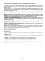
LICENSING INFORMATION
Changes or modifications not expressly approved by Shure Incorporated could void
your authority to operate the equipment. Licensing of Shure wireless microphone equip-
ment is the user’s responsibility, and licensability depends on the user’s classification
and application, and on the selected frequency. Shure strongly urges the user to contact
the appropriate telecommunications authority concerning proper licensing, and before
choosing and ordering frequencies.
R&TTE CONFORMITY INFORMATION
IMPORTANT! Shure Models U1 and U2 Transmitters meet the essential requirements
of the European R&TTE Directive 99/5/EC and are eligible to carry the CE marking.
O682
Shure Model U4 Receivers meet the essential requirements of the European R&TTE Di-
rective 99/5/EC and are eligible to carry the CE marking.
THIS RADIO EQUIPMENT IS INTENDED FOR USE IN MUSICAL PROFESSIONAL
ENTERTAINMENT AND SIMILAR APPLICATIONS.
NOTE: THIS RADIO APPARATUS MAY BE CAPABLE OF OPERATING ON SOME
FREQUENCIES NOT AUTHORIZED IN YOUR REGION. PLEASE CONTACT YOUR
NATIONAL AUTHORITY TO OBTAIN INFORMATION ON AUTHORIZED FREQUEN-
CIES FOR WIRELESS MICROPHONE PRODUCTS IN YOU REGION
Frequency Range of Apparatus: 692 MHz – 862 MHz
Licensing: A ministerial license to operate this equipment may be required in certain
areas. Consult your national authority for possible requirements.
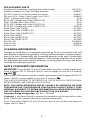
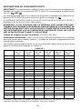
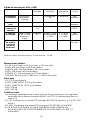
Shure Transmitters Models U1 and U2 may be used in the countries and frequency
ranges listed in Table 1.

7
TABLE 1
Country Code U1-M3, U2-M3
(692 - 716
MHz)
U1-R3, U2-R3
(774 - 782
MHz)
U1-R7, U2-R7
(782 - 810
MHz)
U1-R6, U2-R6
(800 - 820
MHz)
U1-R2, U2-R2
(800 - 320
MHz)
U1-S2, U2-S2
(838 - 862
MHz)
A 692–716 MHz* 774–782 MHz* 782–810 MHz* 800–820 MHz* 800–830 MHz* 838–862 MHz*
B 692–716 MHz* 774–782 MHz* 782–810 MHz* 800–820 MHz* 800–830 MHz* 838–862 MHz*
CH 692–716 MHz* 774–782 MHz* 782–810 MHz* 800–820 MHz* 800–830 MHz* 838–862 MHz*
D 692–716 MHz* 774–782 MHz* 782–810 MHz* 800–820 MHz* 800–830 MHz* 838–862 MHz*
E 692–716 MHz* 774–782 MHz* 782–810 MHz* 800–820 MHz* 800–830 MHz* 838–862 MHz*
F 692–716 MHz* 774–782 MHz* 782–810 MHz* 800–820 MHz* 800–830 MHz* *
GB 692–716 MHz* 774–782 MHz* 782–810 MHz* * * 838–862 MHz*
GR 692–716 MHz* 774–782 MHz* 782–810 MHz* 800–820 MHz* 800–830 MHz* 838–862 MHz*
I 692–716 MHz* 774–782 MHz* 782–810 MHz* * * *
IRL 692–716 MHz* 774–782 MHz* 782–810 MHz* 800–820 MHz* 800–830 MHz* 838–862 MHz*
L 692–716 MHz* 774–782 MHz* 782–810 MHz* 800–820 MHz* 800–830 MHz* 838–862 MHz*
NL 692–716 MHz* 774–782 MHz* 782–810 MHz* 800–820 MHz* 800–830 MHz* 838–862 MHz*
P 692–716 MHz* 774–782 MHz* 782–810 MHz* 800–820 MHz* 800–830 MHz* 838–862 MHz*
DK * * 800–810 MHz* 800–820 MHz* 800–830 MHz* *
FIN * * 800,1–810
MHz*
800,1–819,9
MHz*
800,1–819,9
MHz*
*
N * * 800–810 MHz* 800–820 MHz* 800–830 MHz* *
S * * 800–810 MHz* 800–814 MHz* 800–814 MHz* *
All Other
Countries
* * * * * *
*Please contact your national authority for information on available legal frequencies for your area
and legal use of the equipment.
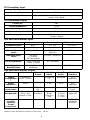
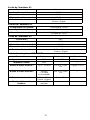
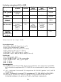
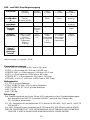
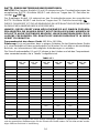
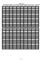
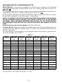
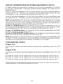
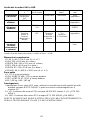
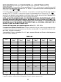
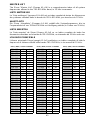
UHF WIRELESS SYSTEM COMPATIBILITY GUIDE
Table 2 provides a convenient overview of frequency–compatible systems in the 774.000
to 782.000 MHz band. Each of the primary groups contains multiple channels which are
all compatible with one another.
Up to 11 Shure UHF Wireless Systems can be operated simultaneouslywithin the
774–782 MHz band if using the discontinued UHF MC versions, or a combination of MC
and MK2 R3 versions. Up to 16 UHF MK2 systems can be operated simultaneously wi-
thin the 774–782 MHz band.
Note: Combinations of Shure UHF transmitters and UHF MK2 receivers, and combina-
tions of UHF MK2 transmitters and UHF receivers are NOT supposed to work together.
Always use a transmitter–receiver combination of the same frequency version (R3 or
MC).
Groups 1–8 MUST be chosen if the installation includes a pure setup of Shure UHF Wi-
reless Systems (frequency version MC only) or a mixed setup of Shure UHF and Shure
UHF MK2 Wireless Systems (frequency versions MC and R3)
Groups 1–8 CAN be chosen if the installation includes a pure setup of Shure UHF MK2
Wireless Systems (frequency version R3 only).
Groups 9–18 CAN ONLY be chosen if the installation includes a pure setup of Shure
UHF MK2 Wireless Systems (frequency version R3 only).

8
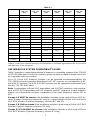
FREQUENCY GROUP CONTENTS
Groups 1–8*
Groups 1–8 provide the maximum number of compatible frequencies between 774 and
782 MHz.
Groups 9–18*
Groups 9–15 provide the maximum number of compatible frequencies between 774 and
782 MHz.
Group 16 complies with the French regulations for user group A.
Groups 17 complies with the French regulations for user group B.
Groups 18 complies with the French regulations for user group C.
* Please contact your national frequency authority to get information on the available legal fre-
quencies for your area and legal use of the equipment.
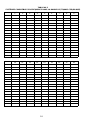
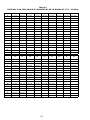
TABLE 2
SYSTEM COMPATIBILITY GUIDE R3 FREQUENCY BAND (774 – 782) MHz
Channel Group 1 Group 2 Group 3 Group 4 Group 5 Group 6 Group 7 Group 8 Group 9
1 774.125 774.250 774.375 774.125 774.250 774.250 774.375 774.250 774.100
2 775.125 775.250 775.125 774.625 775.000 775.000 775.375 774.750 774.400
3 775.625 775.750 776.125 775.625 776.000 775.500 775.875 775.750 775.075
4 776.375 776.500 776.875 776.375 776.750 776.250 776.625 776.500 775.375
5 777.375 777.500 777.375 776.875 777.250 777.250 777.625 777.000 775.900
6 778.000 778.125 778.250 777.750 778.125 777.875 778.250 777.875 776.200
7 778.875 779.000 778.875 778.375 778.750 778.750 779.125 778.500 776.875
8 779.375 779.500 779.875 779.375 779.750 779.250 779.625 779.500 777.175
9 780.125 780.250 780.625 780.125 780.500 780.000 780.375 780.250 778.825
10 781.125 781.250 781.125 780.625 781.000 781.000 781.375 780.750 779.125
11 781.625 781.750 781.875 781.625 781.750 781.750 781.875 781.750 779.800
12 780.100
13 780.625
14 780.925
15 781.600
16 781.900
... MC/R3 MC/R3 MC/R3 MC/R3 MC/R3 MC/R3 MC/R3 MC/R3 R3

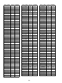
9
Channel Group
10
Group
11
Group
12
Group
13
Group
14
Group
15
Group
16
Group
17
Group
18
1 774.250 774.025 774.025 774.100 774.350 774.200 774.750 774.100 774.300
2 774.550 774.325 774.325 774.550 774.950 774.500 775.500 774.500 775.000
3 775.150 774.925 775.000 774.850 775.250 774.950 776.500 778.225 776.225
4 775.450 775.225 775.525 775.300 775.850 775.250 777.250 778.975 776.975
5 775.900 775.675 775.825 775.900 776.300 776.150 777.750 780.500 778.775
6 776.200 775.975 776.425 776.350 776.900 776.525 778.500 781.300 780.000
7 776.800 776.575 776.875 776.650 777.200 777.200 779.500 781.700 781.500
8 777.100 776.875 777.175 777.550 777.800 778.700 780.250 781.900
9 778.600 778.675 778.075 778.900 779.000 779.300
10 778.900 779.275 779.125 779.350 779.600 779.750
11 779.500 779.575 779.575 779.950 779.900 780.050
12 779.800 780.025 779.875 780.400 780.500 780.500
13 780.250 780.625 780.475 780.700 780.950 781.100
14 780.550 781.000 780.925 781.300 781.550 781.550
15 781.150 781.525 781.525 781.675 781.850 781.850
16 781.450 781.825
... R3 R3 R3 R3 R3 R3 R3 R3 R3

10

11
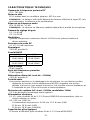
CARACTÉRISTIQUES TECHNIQUES
Gamme de la fréquence porteuse RF
774 – 782 MHz.
Distance utile
152,4 mètres dans les conditions typiques; 487.6 m max.
REMARQUE : La distance utile réelle dépend des facteurs affectant le signal RF, tels
que l’absorption, la réflexion et les perturbations.
Réponse en fréquence audio
50 à 15 000 Hz, "2 dB.
REMARQUE : La réponse en fréquence globale dépend de la qualité du microphone.
Gamme de réglage du gain
U1 : 0 à 40 dB
U2 : 0 à 26 dB
Modulation
Système compresseur–extenseur d’écart "18 kHz avec préaccentuation et
désaccentuation.
Puissance de sortie RF
U1, U2 : 10 mW maximum.
Dynamique
>102 dB, pondéré A
Sensibilité RF
U4S U4D
–110 dBm
12 dB SINAD
–107 dBm
12 dB SINAD
–105 dBm
30 dB SINAD
–102 dBm
30 dB SINAD
Rejet d’image
90 dB (typique)
Rejet des fréquences parasites
75 dB (typique)
Atténuation ultime (réf. écart de "18 kHz)
>100 dB, pondéré A
Polarité audio
Une pression positive sur le diaphragme du microphone (ou une tension positive
appliquée au bout de la fiche téléphonique WA302) engendre une tension
positive à la broche 2 par rapport à la broche 3 de la sortie à basse impédance et
à l’extrémité du jack 1/4 po de la sortie à haute impédance.
Distorsion du système (réf. écart "18 kHz, modulation 1 kHz)
0,3 % de distorsion harmonique totale (typique).
Alimentation électrique
U1, U2 : piles alcalines AA de 1,5 V (Duracell MN1604 recommandées); piles au
nickel–cadmium en option.
U4 : 230 Vca, 50/60 Hz.
Consommation de puissance: 9.6 W min, 13.2 W max (U4S)
12 W min, 16 W max (U4D)
15 W min, 16 W max (UA845A)
Capacité des piles (typique)
12 heures d’utilisation (piles alcalines AA de 1,5 V Duracell MN1500).

12
Température de fonctionnement
–6 à +49 C.
REMARQUE : Les caractéristiques des piles peuvent changer ces valeurs.
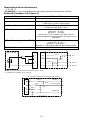
Entrée de l’émetteur U1 (Figure 1)
Connecteur : TA4F o LEMO
Configuration de l’entrée : Asymétrique, active
Impédance réelle : 18 kW avec micro–cravate
1 MW avec cordon d’instrument
Niveau d’entrée maximal : 6 V c–à–c (+7 dBV) pour 1 % DHT; gain
minimal et signal de 1 kHz
Affectation des broches TA4F : Broche 1 : à Masse
Broche 2 : à +5 V
Broche 3 : à Audio
Broche 4 = 20 k à Masse et Audio (Sur le
cordon adaptateur d’instrument, la broche 4 est
flottante)
Affectation des broches LEMO
:
Broche 1 : à Broche 3 et 10 kW à Masse
Broche 2 : à +5 V
Broche 3 : à Broche 1
Broche 4 : à Blindage (Masse por biase positif)
Tension d’alimentation fantôme : +5V alimenté à la cartouche du microphone
NOTA: LE MICRO-CRAVATE RELEI LES MORNES 3 ET 4 , MAIS
LE CORDON DE GUITARE NE LE FAIT PAS.
27 pF
499 Ω
499 Ω
3
27 pF
10K Ω
AUDIO
CIRCUIT DE JACK MICRO U1L (LEMO 4 BROCHES)
1
4
2
BLINDAGE
POLARISATION
27 pF
20K Ω
27 pF
+5 V
AUDIO
2
1
4
500 Ω
500 Ω
3
2
1
3
4
MASSE
MICROPHONE
TABLEAU DE U1
FIGURE 1

13
Sortie de l’émetteur U1
Connecteur : Antenne
Impédance réelle : 50 Ω
Niveau de sortie nominal : +10 dBm
Niveau de sortie maximal : +11 dBm
Affectation des broches : Boîtier = Masse
Centre = Signal
Entrée de l’émetteur U2
Configuration de l’entrée : Asymétrique, active
Impédance réelle : 20 kΩ
Niveau d’entrée maximal : 3 V c–à–c (+0.5 dBV) pour 1 % DHT; gain minimal
et signal de 1 kHz
Sortie de l’émetteur U2
Connecteur : SMC
Impédance réelle : 50 Ω
Niveau de sortie nominal : +10 dBm
Niveau de sortie maximal : +11 dBm
Affectation des broches : Boîtier = Masse
Centre = Signal
Entrée des récepteurs U4S et U4D
Connecteur : Antenne Entrée secteur Interface réseau
Type de connecteur : BNC CEI 320 D 25 broches
Impédance réelle : 50 Ω –– ––
Niveau d’entrée nominal : –95 à –30 dBm 230 Vca, 50/60
Hz
Logique CMOS
Niveau d’entrée maximal :
+6 dBm
(–20 dBm
recommand
é)
254 V ca, 50/60
Hz
––
Affectation des broches : Boîtier = Masse
Centre = Signal
Norme CEI ––
Tension d’alimentatio
fantôme :
12 V cc, 150 mA
maximal
–– ––

14
Sortie des récepteurs U4S et U4D
Connecteur : Écouteurs de
contrôle
Sortie
secteur
Audio à
haute
impédance
Audio à
bass
impédance*
Interface
réseau
Configuratio
n de la sortie
:
Mono
asymétrique,
1/4 po
–– Asymétrique Symétrique Voir
annexe
Impédance
réelle :
300 Ω –– 1 kΩ 30 Ω Voir
annexe
Niveau
d’entrée
nominal :
–– 230 Vca,
5 A
–– –– Logique
CMOS
Affectation
des broches :
Pointe = Sous
tension
Nuque = Sous
tension
Gaine =
Masse
Norme
CEI
Pointe =
Sous
tension
Nuque/gain
e = Masse
1 = Masse
2 = Sous
tension
3 = Sous
tension
Voir
annexe
Protection
tension/
intensité/
alimentation
fantôme
Oui Oui Oui 5V, 700 mA
max.
*Niveau de sortie: mic = ligne – 30 dB
Encombrement
U1 : 92,2 x 64,7 x 24,2 mm (L x Lr x P)
U2/58 : 254 x 50,8 mm (L x diam.)
U2/BETA 58A : 254 x 53,2 mm (L x diam.)
U2/87 : 228,6 x 49,2 mm (L x diam.)
U2/BETA 87 : 216 x 50,8 mm (L x diam.)
U4S/U4D : 44,5 x 482,6 x 295,3 mm (H x Lr x P)
Poids net
U1 : 175,2 g sans piles
U2/58, U2/BETA 58A : 375,6 g sans piles
U2/87, U2/BETA 87 : 303,1 g sans piles
U4S : 3,30 kg
U4D : 3,85 kg
Homologation
Les systèmes sans fil série UHF Shure sont conformes aux exigences essentielles
de la directive européenne R&TTE 99/5/CE et sont autorisés à porter la marque
CE.
U1, U2 : Conforme à la norme ETSI européenne EN 300 422 (parties 1 et 2) et ETS
300 445/A1.
U4, U4D : Conforme à la norme ETSI européenne ETS 300 445/A1 et EN 60950.
CE MATÉRIEL RADIO EST PRÉVU POUR UTILISATION EN SPECTACLES
PROFESSIONNELS (CLASSE I) ET APPLICATIONS SIMILAIRES.

15
ACCESSOIRES FOURNIS
Adaptateur de support de microphone (U2) WA371. . . . . . . . . . . . . . . . . . . . . . . . . . . . .
Pochette à fermeture éclair (U1) 26A13. . . . . . . . . . . . . . . . . . . . . . . . . . . . . . . . . . . . . . . .
Pochette à fermeture éclair (U2) 26A14. . . . . . . . . . . . . . . . . . . . . . . . . . . . . . . . . . . . . . . .
Tournevis 80A498. . . . . . . . . . . . . . . . . . . . . . . . . . . . . . . . . . . . . . . . . . . . . . . . . . . . . . . . . .
Câble coaxial d’antenne (60 cm) UA802. . . . . . . . . . . . . . . . . . . . . . . . . . . . . . . . . . . . . . .
Antenne demi–onde (774 à 782MHz) UA820A. . . . . . . . . . . . . . . . . . . . . . . . . . . . . . . . .
Valise de transport pour l’émetteur 65A8257. . . . . . . . . . . . . . . . . . . . . . . . . . . . . . . . . . . .
Insertion de valise de transport 29B1577. . . . . . . . . . . . . . . . . . . . . . . . . . . . . . . . . . . . . . .
ACCESSOIRES EN OPTION
Cordon adaptateur d’instrument (U1) WA302/WA304. . . . . . . . . . . . . . . . . . . . . . . . . . . .
Connecteur femelle 4 broches miniatur TA4F (U1) WA330. . . . . . . . . . . . . . . . . . . . . . .
Commutateur audio en ligne (U1) WA360. . . . . . . . . . . . . . . . . . . . . . . . . . . . . . . . . . . . . .
Câble d’interface récepteur–mélangeur de 1,80 m (fiche
téléphonique 1/4 po et fiche XLR) WA410. . . . . . . . . . . . . . . . . . . . . . . . . . . . . . . . . . .
Rallonge d’antenne de 7,6 m UA825. . . . . . . . . . . . . . . . . . . . . . . . . . . . . . . . . . . . . . . . . .
Rallonge d’antenne de 15,2 m UA850. . . . . . . . . . . . . . . . . . . . . . . . . . . . . . . . . . . . . . . . .
Rallonge d’antenne de 30,4 m UA8100. . . . . . . . . . . . . . . . . . . . . . . . . . . . . . . . . . . . . . . .
Kit d’antenne active à distance en ligne (774 – 782 MHz) UA830D. . . . . . . . . . . . . . . .
Système répartiteur d’antennes/alimentation, 230 Vca UA845MC. . . . . . . . . . . . . . . . .
Antenne directionelle UA870MC. . . . . . . . . . . . . . . . . . . . . . . . . . . . . . . . . . . . . . . . . . . . .
PIÈCES DE RECHANGE
Kit d’installation (tournevis, pieds, serre–câbles) 90VL1371. . . . . . . . . . . . . . . . . . . . . .
Adaptateurs de montage des antennes à l’avant 95A8647. . . . . . . . . . . . . . . . . . . . . . . .
Cordon d’alimentation 230 Vca 95A8247. . . . . . . . . . . . . . . . . . . . . . . . . . . . . . . . . . . . . . .
Cordon d’alimentation en série 304 mm (230 V) 85A8678. . . . . . . . . . . . . . . . . . . . . . . .
Cartouche SM58
avec grille (U2/58) R158. . . . . . . . . . . . . . . . . . . . . . . . . . . . . . . . . . . .
Cartouche BETA 58A avec grille (U2/BETA 58) R179. . . . . . . . . . . . . . . . . . . . . . . . . . . .
Cartouche SM87 avec grille (U2/87) R165. . . . . . . . . . . . . . . . . . . . . . . . . . . . . . . . . . . . .
Cartouche BETA 87A avec grille (U2/BETA 87) R166. . . . . . . . . . . . . . . . . . . . . . . . . . . .
Cartouche BETA 87C avec grille (U2/BETA 87) RPW100. . . . . . . . . . . . . . . . . . . . . . . . .
Grille argent mat (U2/58) RK143G. . . . . . . . . . . . . . . . . . . . . . . . . . . . . . . . . . . . . . . . . . . .
Grille argent mat (U2/BETA 58) RK265G. . . . . . . . . . . . . . . . . . . . . . . . . . . . . . . . . . . . . . .
Grille argent mat (U2/BETA 87) RK313G. . . . . . . . . . . . . . . . . . . . . . . . . . . . . . . . . . . . . . .
Grille noire (U2/87) RK214G. . . . . . . . . . . . . . . . . . . . . . . . . . . . . . . . . . . . . . . . . . . . . . . . .
Grille noire (U2/BETA 58) RK323G. . . . . . . . . . . . . . . . . . . . . . . . . . . . . . . . . . . . . . . . . . . .
Grille noire (U2/BETA 87) RK324G. . . . . . . . . . . . . . . . . . . . . . . . . . . . . . . . . . . . . . . . . . . .
Pince de ceinture (U1) 53A8247A. . . . . . . . . . . . . . . . . . . . . . . . . . . . . . . . . . . . . . . . . . . .
Antenne (U1) 95A8646. . . . . . . . . . . . . . . . . . . . . . . . . . . . . . . . . . . . . . . . . . . . . . . . . . . . . .
Antenne (U2) 95A2029. . . . . . . . . . . . . . . . . . . . . . . . . . . . . . . . . . . . . . . . . . . . . . . . . . . . . .
RENSEIGNEMENTS SUR L’OCTROI DE LICENCE
Tout changement ou modification n’ayant pas fait l’objet d’une autorisation expresse de
Shure Incorporated peut entraîner la nullité du droit d’utilisation de l’équipement. La li-
cence d’utilisation de l’équipement du microphone sans fil Shure demeure la responsa-
bilité de l’utilisateur, et elle dépend de la classification de l’utilisateur et de l’application
prévue par lui ainsi que de la fréquence sélectionnée. Shure recommande vivement de
se mettre en rapport avec les autorités compétentes des télécommunications pour
l’obtention des autorisations nécessaires, ainsi qu’avant de choisir et de commander
des fréquences.

16
INFORMATIONS DE CONFORMITÉ R&TTE
IMPORTANT ! Les transmetteurs modèles Shure U1 et U2 conforme aux exigences es-
sentielles de la directive européenne R&TTE 99/5/CE et sont autorisés à porter la mar-
que CE.
O682
Le recepteur modèle Shure U4 conforme aux exigences essentielles de la directive euro-
péenne R&TTE 99/5/CE et sont autorisés à porter la marque CE.
CE MATÉRIEL RADIO EST PRÉVU POUR UTILISATION EN SPECTACLES PROFES-
SIONNELS ET APPLICATIONS SIMILAIRES.
REMARQUE : IL EST POSSIBLE QUE CE MATÉRIEL SOIT CAPABLE DE FONC-
TIONNER SUR CERTAINES FRÉQUENCES NON AUTORISÉES LOCALEMENT. SE
METTRE EN RAPPORT AVEC LES AUTORITÉS COMPÉTENTES POUR OBTENIR
LES INFORMATIONS SUR LES FRÉQUENCES AUTORISÉES POUR LES SYSTÈ-
MES DE MICROPHONES SANS FIL LOCALEMENT
Gamme de fréquences pour ce matériel : 692 MHz–862 MHz
Autorisation d’utilisation : Noter qu’une licence officielle d’utilisation de ce matériel
peut être requise dans certains endroits. Consulter les autorités compétentes pour les
spécifications possibles.
Les modèles d’transmetteur Shure U1 et U2 peuvent être utilisés dans les pays et aux
gammes de fréquences indiqués au Tableau 1.
TABLEAU 1
Code de Pays U1-M3, U2-M3
(692 - 716
MHz)
U1-R3, U2-R3
(774 - 782
MHz)
U1-R7, U2-R7
(782 - 810
MHz)
U1-R6, U2-R6
(800 - 820
MHz)
U1-R2, U2-R2
(800 - 320
MHz)
U1-S2, U2-S2
(838 - 862
MHz)
A 692–716 MHz* 774–782 MHz* 782–810 MHz* 800–820 MHz* 800–830 MHz* 838–862 MHz*
B 692–716 MHz* 774–782 MHz* 782–810 MHz* 800–820 MHz* 800–830 MHz* 838–862 MHz*
CH 692–716 MHz* 774–782 MHz* 782–810 MHz* 800–820 MHz* 800–830 MHz* 838–862 MHz*
D 692–716 MHz* 774–782 MHz* 782–810 MHz* 800–820 MHz* 800–830 MHz* 838–862 MHz*
E 692–716 MHz* 774–782 MHz* 782–810 MHz* 800–820 MHz* 800–830 MHz* 838–862 MHz*
F 692–716 MHz* 774–782 MHz* 782–810 MHz* 800–820 MHz* 800–830 MHz* *
GB 692–716 MHz* 774–782 MHz* 782–810 MHz* * * 838–862 MHz*
GR 692–716 MHz* 774–782 MHz* 782–810 MHz* 800–820 MHz* 800–830 MHz* 838–862 MHz*
I 692–716 MHz* 774–782 MHz* 782–810 MHz* * * *
IRL 692–716 MHz* 774–782 MHz* 782–810 MHz* 800–820 MHz* 800–830 MHz* 838–862 MHz*
L 692–716 MHz* 774–782 MHz* 782–810 MHz* 800–820 MHz* 800–830 MHz* 838–862 MHz*
NL 692–716 MHz* 774–782 MHz* 782–810 MHz* 800–820 MHz* 800–830 MHz* 838–862 MHz*
P 692–716 MHz* 774–782 MHz* 782–810 MHz* 800–820 MHz* 800–830 MHz* 838–862 MHz*
DK * * 800–810 MHz* 800–820 MHz* 800–830 MHz* *
FIN * * 800,1–810
MHz*
800,1–819,9
MHz*
800,1–819,9
MHz*
*
N * * 800–810 MHz* 800–820 MHz* 800–830 MHz* *
S * * 800–810 MHz* 800–814 MHz* 800–814 MHz* *
Tous les
autres pays
* * * * * *
*Se mettre en rapport avec les autorités compétentes pour obtenir les informations sur les fréquences
autorisées disponibles localement et sur l’utilisation autorisée du matériel.

17
GUIDE DE COMPATIBILITÉ DU SYSTÈME SANS FIL R3 UHF
Le Tableau 2 suivant donne une liste générale des systèmes compatibles en fréquence
dans la bande de 774,000 à 782,000 MHz. Chaque groupe comprend plusieurs canaux
compatibles les uns avec les autres.
Jusqu’à 11 systèmes sans fil UHF Shure peuvent être utilisés simultanément dans la
bande de 774 à 782 MHz si ces systèmes sont de versions de fréquence MC (abandon-
nées) ou d’une combinaison de versions MC et R3.
Jusqu’à 16 systèmes sans fil MK2 UHF Shure peuvent être utilisés simultanément dans
la bande de 774 à 782 MHz s’ils sont tous de versions de fréquence R3.
Remarque : Les combinaisons d’émetteurs UHF Shure et de récepteurs MK2 UHF Shu-
re ainsi que les combinaisons d’émetteurs MK2 UHF Shure et de récepteurs UHF Shure
NE SONT PAS censées fonctionner. Toujours utiliser les combinaisons émetteurs–ré-
cepteurs de même version de fréquence (R3 ou MC).
Les groupes 1 à 8 DOIVENT être utilisés si l’installation comprend des systèmes sans
fil UHF Shure (fréquence MC seulement) ou des systèmes sans fil UHF Shure et des sys-
tèmes sans fil MK2 UHF Shure (fréquences MC et R3)
Les groupes 1 à 8 PEUVENT être utilisés si l’installation comprend des systèmes sans
fil MK2 UHF Shure seulement (versions de fréquence R3).
Les groupes 9 à 18 peuvent UNIQUEMENT être utilisés si l’installation comprend des
systèmes sans fil MK2 UHF Shure seulement (versions de fréquence R3).
Remarque : Il est possible que cet appareil soit capable de fonctionner sur certaines fré-
quences non autorisées localement. Se mettre en rapport avec les autorités compéten-
tes pour obtenir les informations sur les fréquences autorisées pour les microphones
sans fil localement.
COMPOSANTS DES GROUPES
Groupes 1 à 8*
Les groupes 1 à 8 offrent le nombre maximum de fréquences compatibles entre 774 et
782 MHz.
Groupes 9 à 18*
Les groupes 9 à 15 offrent le nombre maximum de fréquences compatibles entre 774 et
782 MHz.
Le groupe 16 conforme aux réglementations françaises pour le groupe d’utilisateurs A.
Le groupe 17 conforme aux réglementations françaises pour le groupe d’utilisateurs B.
Le groupe 18 conforme aux réglementations françaises pour le groupe d’utilisateurs C.
*Se mettre en rapport avec les autorités compétentes pour obtenir les informations sur les fré-
quences autorisées disponibles localement et sur l’utilisation autorisée du matériel.

18
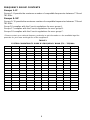
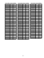
TABLEAU 2
SYSTÈMES COMPATIBLES EN FRÉQUENCE DANS LA BANDE R3 (774,000 À 782,000 MHZ)
Channel Groupe
1
Groupe
2
Groupe
3
Groupe
4
Groupe
5
Groupe
6
Groupe
7
Groupe
8
Groupe
9
1 774.125 774.250 774.375 774.125 774.250 774.250 774.375 774.250 774.100
2 775.125 775.250 775.125 774.625 775.000 775.000 775.375 774.750 774.400
3 775.625 775.750 776.125 775.625 776.000 775.500 775.875 775.750 775.075
4 776.375 776.500 776.875 776.375 776.750 776.250 776.625 776.500 775.375
5 777.375 777.500 777.375 776.875 777.250 777.250 777.625 777.000 775.900
6 778.000 778.125 778.250 777.750 778.125 777.875 778.250 777.875 776.200
7 778.875 779.000 778.875 778.375 778.750 778.750 779.125 778.500 776.875
8 779.375 779.500 779.875 779.375 779.750 779.250 779.625 779.500 777.175
9 780.125 780.250 780.625 780.125 780.500 780.000 780.375 780.250 778.825
10 781.125 781.250 781.125 780.625 781.000 781.000 781.375 780.750 779.125
11 781.625 781.750 781.875 781.625 781.750 781.750 781.875 781.750 779.800
12 780.100
13 780.625
14 780.925
15 781.600
16 781.900
... MC/R3 MC/R3 MC/R3 MC/R3 MC/R3 MC/R3 MC/R3 MC/R3 R3
Channel Groupe
10
Groupe
11
Groupe
12
Groupe
13
Groupe
14
Groupe
15
Groupe
16
Groupe
17
Groupe
18
1 774.250 774.025 774.025 774.100 774.350 774.200 774.750 774.100 774.300
2 774.550 774.325 774.325 774.550 774.950 774.500 775.500 774.500 775.000
3 775.150 774.925 775.000 774.850 775.250 774.950 776.500 778.225 776.225
4 775.450 775.225 775.525 775.300 775.850 775.250 777.250 778.975 776.975
5 775.900 775.675 775.825 775.900 776.300 776.150 777.750 780.500 778.775
6 776.200 775.975 776.425 776.350 776.900 776.525 778.500 781.300 780.000
7 776.800 776.575 776.875 776.650 777.200 777.200 779.500 781.700 781.500
8 777.100 776.875 777.175 777.550 777.800 778.700 780.250 781.900
9 778.600 778.675 778.075 778.900 779.000 779.300
10 778.900 779.275 779.125 779.350 779.600 779.750
11 779.500 779.575 779.575 779.950 779.900 780.050
12 779.800 780.025 779.875 780.400 780.500 780.500
13 780.250 780.625 780.475 780.700 780.950 781.100
14 780.550 781.000 780.925 781.300 781.550 781.550
15 781.150 781.525 781.525 781.675 781.850 781.850
16 781.450 781.825
... R3 R3 R3 R3 R3 R3 R3 R3 R3

19
SPEZIFIKATIONEN
Frequenzbereich
774 – 782 MHz
Reichweite
150 m Minimum unter Normalbedingungen; 500 m maximal
HINWEIS: Die tatsächliche Reichweite hängt von der HF-Signalabsorption,
-reflexion und -interferenz ab.
Audiofrequenzgang
50 bis 15,000 Hz, "2 dB.
HINWEIS: Der Gesamtaudiofrequenzgang des Systems hängt vom
Mikrophonelement ab.
Verstärkungsbereich
U1: 0 bis 40 dB
U2: 0 bis 26 dB
Modulation
"18 kHz Komprimierungs–/Dekomprimierungssystem mit Preemphasis und
Deemphasis.
Dynamikbereich
>102 dB, mit A–Bewertung
HF–Empfindlichkeit:
U4S U4D
–110 dBm
12 dB SINAD
–107 dBm
12 dB SINAD
–105 dBm
30 dB SINAD
–102 dBm
30 dB SINAD
HF–Leistungsabgabe
U1, U2: maximal 10 mW
Spiegelselektion
90 dB (typisch)
Oberwellenunterdrückung
75 dB (typisch)
Grenzschalldämmung (bzgl. "18 kHz Abweichung)
>100 dB, mit A–Bewertung
Audiopolarität
Positiver Druck auf die Mikrophonmembran (oder positive Spannung an der Spitze
des Klinkensteckers WA302) erzeugt positive Spannung an Pin 2 hinsichtlich Pin
3 des Niederimpedanzausgangs und der Spitze des
Hochimpedanz–6,3mm–Ausgangs.
Systemverzerrung (bzgl. "18 kHz Abweichung, 1 kHz Modulation)
0,3% Gesamtklirrfaktor (typisch)
Stromversorgung
U1, U2: 1,5–V–Alkalibatterie (Duracell MN 1500 wird empfohlen), wahlweise NiCd
U4: 230 V Wechselstrom, 50/60 Hz
Leistungsaufnahme: 9.6 W min, 13.2 W max (U4S)
12 W min, 16 W max (U4D)
15 W min, 16 W max (UA845)
Batterielebensdauer Sender (typisch)
12 Stunden (für Duracell MN 1500 1,5–V–Alkalibatterien)

20
Betriebstemperaturbereich
–6 bis +49 C
HINWEIS: Batterieeigenschaften können diesen Bereich einschränken.
U1–Sendereingang (Abbildung 1)
Anschluß: TA4F oder LEMO
Eingangskonfiguration: Asymmetrisch, aktiv
Tatsächliche Impedanz:
18 k Bei Lavalier–Mikrophon
1M mit Instrumentenkabel
Maximaler Eingangs-pegel: 6 Vss (+7 dBV) für 1% Gesamtklirrfaktor bei minimaler
Verstärkungseinstellung mit 1 kHz Signal
TA4F Pinkonfiguration: Pin 1: Erdung
Pin 2: +5V
Pin 3: Audio
Pin 4 : an 20 kΩ für Erdung & Audio (bei
Instrumentenadapterkabeln ist Pin 4 nicht geerdet)
LEMO Pinkonfiguration: Pin 1: an Pin 3 und 10 kΩ an Erdung
Pin 2: +5V
Pin 3: Pin 1
Pin 4: an der Schirmung (Erdung)
Spannung für
Phantomspeisung:
+5 V Versorgung an Mikrophonkapsel
27 pF
20K Ω
27 pF
+5 V
AUDIO
2
1
4
500 Ω
500 Ω
3
2
1
3
4
HINWEIS: DAS LAVALIERKABEL VERBINDET Pin 3 UND 4; DAS
GITARRENKABEL ERFÜLLT DIESE FUNKTION NICHT
MIKROPHON
ELEMENT
U1 MIKROPHON–KLINKENPLATTE
ERDUNG
ABSCHIRMUNG
27 pF
499 Ω
499 Ω
3
27 pF
10K Ω
AUDIO
1
4
2
VORSPANNUNG
U1L (LEMO–4 POLIG) MIKROFONBUCHSE
ABBILDUNG 1
La pagina sta caricando ...
La pagina sta caricando ...
La pagina sta caricando ...
La pagina sta caricando ...
La pagina sta caricando ...
La pagina sta caricando ...
La pagina sta caricando ...
La pagina sta caricando ...
La pagina sta caricando ...
La pagina sta caricando ...
La pagina sta caricando ...
La pagina sta caricando ...
La pagina sta caricando ...
La pagina sta caricando ...
La pagina sta caricando ...
La pagina sta caricando ...
La pagina sta caricando ...
La pagina sta caricando ...
La pagina sta caricando ...
La pagina sta caricando ...
La pagina sta caricando ...
La pagina sta caricando ...
La pagina sta caricando ...
La pagina sta caricando ...
La pagina sta caricando ...
La pagina sta caricando ...
La pagina sta caricando ...
La pagina sta caricando ...
-
 1
1
-
 2
2
-
 3
3
-
 4
4
-
 5
5
-
 6
6
-
 7
7
-
 8
8
-
 9
9
-
 10
10
-
 11
11
-
 12
12
-
 13
13
-
 14
14
-
 15
15
-
 16
16
-
 17
17
-
 18
18
-
 19
19
-
 20
20
-
 21
21
-
 22
22
-
 23
23
-
 24
24
-
 25
25
-
 26
26
-
 27
27
-
 28
28
-
 29
29
-
 30
30
-
 31
31
-
 32
32
-
 33
33
-
 34
34
-
 35
35
-
 36
36
-
 37
37
-
 38
38
-
 39
39
-
 40
40
-
 41
41
-
 42
42
-
 43
43
-
 44
44
-
 45
45
-
 46
46
-
 47
47
-
 48
48


Shure R3 Manuale del proprietario
- Categoria
- Microfoni
- Tipo
- Manuale del proprietario
in altre lingue
- français: Shure R3 Le manuel du propriétaire