Pioneer DEH-P65BT Guida d'installazione
- Categoria
- Microfoni
- Tipo
- Guida d'installazione

MANUEL D’INSTALLATION
DEH-P65BT
INSTALLATION MANUAL
English
Español
Deutsch
Français
Italiano
Nederlands
PyÒÒÍËÈ
This product conforms to new cord colors.
Los colores de los cables de este producto se confor-
man con un nuevo código de colores.
Dieses Produkt entspricht den neuen Kabelfarben.
Le code de couleur des câbles utilisé pour ce produit est
nouveau.
Questo prodotto è conforme ai nuovi codici colori.
De kleuren van de snoeren van dit toestel zijn gewijzigd.
чÌÌÓ ÛÒÚÓÈÒÚ‚Ó ÒÓÓÚ‚ÂÚÒÚ‚ÛÂÚ ÌÓ‚˚Ï
Ú·ӂ‡ÌËflÏ Í ˆ‚ÂÚÛ ÔÓ‚Ó‰Ó‚.

1
Connecting the Units ................................ 1
Power cable connection .................................... 3
Connecting to separately sold power amp ........ 5
Installation .................................................. 7
DIN Front/Rear-mount ...................................... 7
DIN Front-mount .............................................. 7
DIN Rear-mount ................................................ 8
Fastening the front panel .................................. 9
Installing the microphone .................................. 9
Adjusting the microphone angle ......................10
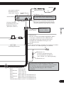
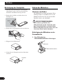
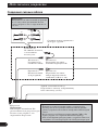
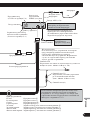
Connecting the Units
Contents
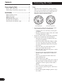
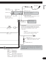
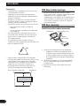
Note:
• When this unit is installed in a vehicle without
ACC (accessory) position on the ignition switch,
red cable must be wired to the terminal that can
detect the operation of the ignition key.
Otherwise, battery drain may result.
• Use this unit in other than the following condi-
tions could result in fire or malfunction.
— Vehicles with a 12-volt battery and negative
grounding.
— Speakers with 50 W (output value) and 4 ohm
to 8 ohm (impedance value).
• To prevent short-circuit, overheating or malfunc-
tion, be sure to follow the directions below.
— Disconnect the negative terminal of the bat-
tery before installation.
— Secure the wiring with cable clamps or adhe-
sive tape. To protect the wiring, wrap adhe-
sive tape around them where they lie against
metal parts.
— Place all cables away from moving parts,
such as gear shift and seat rails.
— Place all cables away from hot places, such as
near the heater outlet.
— Do not pass the yellow cable through a hole
into the engine compartment to connect to a
battery.
— Cover any disconnected cable connectors
with insulating tape.
— Do not shorten any cables.
— Never cut the insulation of the power cable of
this unit in order to share the power to other
equipment. Current capacity of the cable is
limited.
— Use a fuse of the rating prescribed.
— Never wire the speaker negative cable direct-
ly to ground.
— Never band together multiple speaker’s nega-
tive cables.
No ACC positionACC position
O
N
S
T
A
R
T
O
F
F
A
C
C
O
N
S
T
A
R
T
O
F
F

English
Español
Deutsch
Français
Italiano
Nederlands
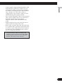
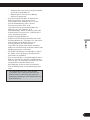
• Control signal is output through blue/white cable
when this unit is powered on. Connect it to an
external power amp’s system remote control or
the vehicle’s auto-antenna relay control terminal
(max. 300 mA, 12 V DC). If the vehicle is
equipped with a glass antenna, connect it to the
antenna booster power supply terminal.
• Never connect blue/white cable to external power
amp’s power terminal. Also, never connect it to
the power terminal of the auto antenna.
Otherwise, battery drain or malfunction may
result.
• IP-BUS connectors are color-coded. Be sure to
connect connectors of the same color.
• Black cable is ground. This cable and other prod-
uct’s ground cable (especially, high-current prod-
ucts such as power amp) must be wired separate-
ly. Otherwise, fire or malfunction may result if
they are accidentally detached.
• Cord function may differ according to the
product, even if cord color is the same. When
connecting this system, be sure to check all
manuals and connect cords correctly.
2
FRANÇAIS

3
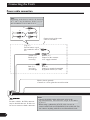
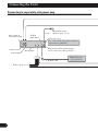
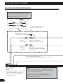
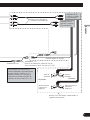
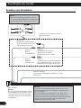
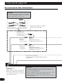
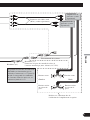
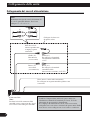
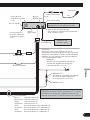
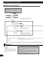
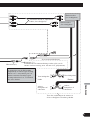
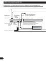
Connecting the Units
1*
2*
4*
3*
5*
N
ote
:
Dependin
g
on the kind of vehicle, the function
of 3* and 5* ma
y
be different. In this case, be
sure to connect 2* to
5
* and 4* to
3
*
.
Connect leads of the same
color to each other.
Cap (1*)
Do not remove cap if
this terminal is not in
use.
Yellow (3*)
Back-up (or
accessory)
Red (5*)
Accessory
(or back-up)
Yellow (2*)
Connect to the constant
12 V supply terminal.
Red (4*)
Connect to terminal controlled
by ignition switch (12 V DC).
N
ote
:
In some vehicles
,
the ISO connecto
r
ma
y
be divided into two. In this case,
be sure to connect to both connectors.
N
otes
:
•
Chan
g
e the initial settin
g
of this unit (refer to the
O
p
eration Manual). The subwoofer out
p
ut of this unit is
monaural
.
•
When usin
g
a subwoofer of 70 W (2
Ω) , be sure to
connect with Violet and Violet/black leads of this unit. Do
not connect anything with Green and Green/black leads.
Black (chassis ground)
Connect to a clean, paint-free metal location.
Power cable connection

English
Español
Deutsch
Français
Italiano
Nederlands
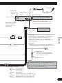
4
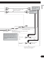
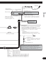
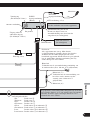
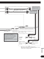
Speaker leads
White: Front left +
White/black: Front left ≠
Gray: Front right +
Gray/black: Front right ≠
Green: Rear left + or subwoofer +
Green/black: Rear left ≠ or subwoofer ≠
Violet: Rear right + or subwoofer +
Violet/black: Rear right ≠ or subwoofer ≠
Blue/white
Connect to system control terminal of the
power amp (max. 300 mA 12 V DC).
Blue/white (7*)
Connect to auto-antenna relay control
terminal (max. 300 mA 12 V DC).
The pin position of the ISO connector will differ depends
on the type of vehicle. Connect 6* and 7* when Pin 5 is
an antenna control type. In another type of vehicle, never
connect 6* and 7*.
Yellow/black
If you use an equipment with Mute function, wire
this lead to the Audio Mute lead on that equipment.
If not, keep the Audio Mute lead free of any
connections.
4 m
This product
Rear output or
subwoofer output
(Refer to page 5 to 6.)
Front output
(Refer to page 5 to 6.)
Antenna jack
Fuse (10 A)
Fuse resistor
AUX
j
ack (3.5
ø
)
Wired remote in
p
u
t
H
ard-wired remote control ada
p
tor can be
connected (sold separately)
.
IP-BUS input
(Blue)
IP-BUS cable
Multi-CD pla
y
e
r
(sold separately)
Blue/white (6*)
14 cm
Use a stereo mini plu
g
cable to connec
t
with auxiliar
y
equipment
.
Microphone
Microphone input

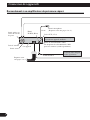
5
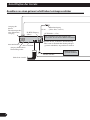
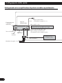
Connecting the Units
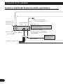
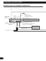
This product
Rear output or
subwoofer output
Front output
Antenna jack
AUX jack (3.5 ø)
Wired remote input
W
H
ard-wired remote control ada
p
to
r
can be connected (sold separatel
y
)
.
IP-BUS
input (Blue)
IP-BUS cable
Multi-CD player
(sold separately)
14 cm
Use a stereo mini plu
g
cable to connec
t
with auxiliar
y
equipment
.
Refer to page 3 to 4.
Microphone input
(Refer to page 3 to 4.)
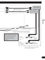
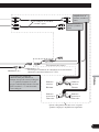
Connecting to separately sold power amp

English
Español
Deutsch
Français
Italiano
Nederlands
6
++
++
≠≠
≠≠
Connect with RCA cables
(sold separately)
Blue/white (7*)
Connect to auto-antenna relay control terminal
(max. 300 mA 12 V DC).
Rear speaker or
subwoofer
Perform these connections when
using the optional amplifier.
Power amp (sold
separately)
Power amp (sold
separately)
System remote control
Blue/white (6*)
Front speaker
Front speaker
Left
Right
Rear speaker or
subwoofer
The pin position of the ISO connector
will differ depends on the type of
vehicle. Connect 6* and 7* when Pin
5 is an antenna control type. In
another type of vehicle, never connect
6* and 7*.

7
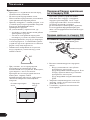
Installation
Note:
• Check all connections and systems before final
installation.
• Do not use unauthorized parts. The use of
unauthorized parts may cause malfunctions.
• Consult with your dealer if installation requires
drilling of holes or other modifications of the
vehicle.
• Do not install this unit where:
— it may interfere with operation of the vehicle.
— it may cause injury to a passenger as a result
of a sudden stop.
• The semiconductor laser will be damaged if it
overheats. Install this unit away from hot places
such as near the heater outlet.
• Optimum performance is obtained when the unit
is installed at an angle of less than 60°.
• When installing, to ensure proper heat dispersal
when using this unit, make sure you leave ample
space behind the rear panel and wrap any loose
cables so they are not blocking the vents.
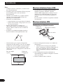
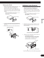
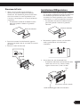
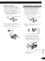
DIN Front/Rear-mount
This unit can be properly installed either from
“Front” (conventional DIN Front-mount) or
“Rear” (DIN Rear-mount installation, utilizing
threaded screw holes at the sides of unit chassis).
For details, refer to the following installation
methods.
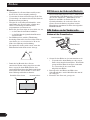
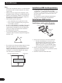
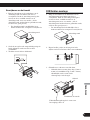
DIN Front-mount
Installation with the rubber bush
1. Insert the mounting sleeve into the dashboard.
• When installing in a shallow space, use a sup-
plied mounting sleeve. If there is enough
space behind the unit, use factory supplied
mounting sleeve.
2. Secure the mounting sleeve by using a screwdriv-
er to bend the metal tabs (90°) into place.
3. Install the unit as illustrated.
53
53
1
1
182182
10 cm
10 cm
60°
Rubber bush
Screw
Dashboard
Mounting sleeve
Leave ample space
Dashboard

8
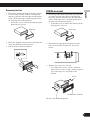
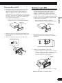
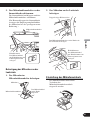
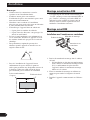
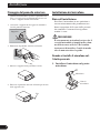
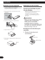
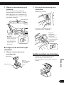
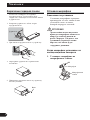
Removing the Unit
1. Extend top and bottom of the trim ring outwards
to remove the trim ring. When reattaching the
trim ring, push the trim ring onto the unit until it
clicks. (If the trim ring is attached upside down,
the trim ring will not fit properly.)
• It becomes easy to remove the trim ring if the
front panel is released.
2. Insert the supplied extraction keys into both sides
of the unit until they click into place.
3. Pull the unit out of the dashboard.
DIN Rear-mount
1. Extend top and bottom of the trim ring outwards
to remove the trim ring. When reattaching the
trim ring, push the trim ring onto the unit until it
clicks. (If the trim ring is attached upside down,
the trim ring will not fit properly.)
• It becomes easy to remove the trim ring if the
front panel is released.
2. Determine the appropriate position where the
holes on the bracket and the side of the unit
match.
3. Tighten two screws on each side.
• Use either truss screws (5 mm × 8 mm) or
flush surface screws (5 mm × 9 mm), depend-
ing on the shape of screw holes in the
bracket.
Trim ring
Trim ring
Screw
Dashboard or Console
Factory radio mounting bracket
English
Español
Deutsch
Français
Italiano
Nederlands

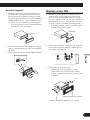
9
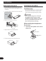
Installation
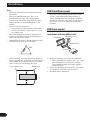
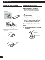
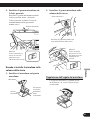
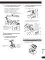
Fastening the front panel
If you do not plan to detach the front panel, the
front panel can be fastened with supplied screws
and holders.
1. Attach the holders to both sides of the front panel.
2. Replace the front panel to the unit.
3. Flip the holders into upright positions.
4. Fix the front panel to the unit using screws.
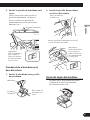
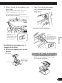
Installing the microphone
Installation notes
Install the microphone in a position and ori-
entation that will enable it to pick up the
voice of the person operating the system.
CAUTION
It is extremely dangerous to allow the
microphone lead to become wound
around the steering column or gearstick.
Be sure to install the unit in such a way
that it will not obstruct driving.
When installing the microphone on
the sun visor
1. Install the microphone on the micro-
phone clip.
Screw
Holder
Microphone
Microphone
clip

10
English
Español
Deutsch
Français
Italiano
Nederlands
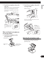
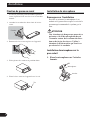
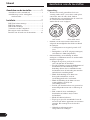
2. Install the microphone clip on the
sun visor.
With the sun visor up, install the micro-
phone clip. (Lowering the sun visor
reduces the recognition rate for voice
operations.)
When installing the microphone on
the steering column
1. Install the microphone on the
microphone clip.
2. Install the microphone clip on the
steering column.
Adjusting the microphone angle
The microphone angle can be adjusted by
moving forward or backward the micro-
phone clip angle.
Microphone clip
Clamps
Use clamps to secure
the lead where neces-
sary inside the vehi-
cle.
Microphone
Microphone
clip
Fit the micro-
phone lead into
the groove.
Double-sided tape
Install the microphone clip on the rear side
of the steering column.
Clamps
Use clamps to
secure the lead
where necessary
inside the vehicle.

1
Conexión de las unidades ........................ 1
Conexión del cable de alimentación .................. 3
Conexión al amplificador de potencia vendido
separadamente ............................................ 5
Instalación .................................................. 7
Montaje delantero/trasero DIN .......................... 7
Montaje delantero DIN ...................................... 7
Montaje trasero DIN .......................................... 8
Fijación del panel delantero .............................. 9
Instalación del micrófono .................................. 9
Ajuste del ángulo del micrófono .................... 10
Conexión de las unidades
Contenido
Nota:
• Cuando se instale esta unidad en un vehículo sin
la posición ACC (accesorio) en el interruptor de
encendido, se debe conectar el cable rojo al
terminal que puede detectar la operación de la
llave de encendido.
De lo contrario, la batería puede descargarse.
• El uso de esta unidad en condiciones diferentes
de las siguientes podría causar un fuego o fallo
de funcionamiento.
— Vehículos con una batería de 12 voltios y
puesta a tierra negativa.
— Altavoz con 50 W (valor de salida) y de 4 a 8
ohmios (valor de impedancia).
• Para prevenir cortocircuitos, sobrecalentamiento
o fallo de funcionamiento, asegúrese de seguir
las instrucciones a continuación.
— Desenchufe el terminal negativo de la batería
antes de la instalación.
— Fije el cableado con abrazaderas de cable o
con cinta adhesiva. Para proteger el cableado,
envuélvalo con cinta adhesiva donde el
cableado se apoya sobre piezas metálicas.
— Posicione todos los cables alejados de las
piezas móviles, como el cambio de marchas y
rieles de los asientos.
— Posicione todos los cables alejados de lugares
calientes como cerca de la salida del
calentador.
— No pase el cable amarillo a través de un
agujero en el compartimiento del motor para
conectar la batería.
— Cubra cualquier conector de cable
desconectado con cinta de aislamiento.
— No acorte ningún cable.
— No corte nunca el aislamiento del cable de
alimentación de esta unidad para compartir la
energía con otro equipo. La capacidad de
corriente del cable es limitada.
— Utilice un fusible con la capacidad
especificada.
— No conecte nunca el cable negativo de
altavoz directamente a la puesta a tierra.
— No junte nunca múltiples cables negativos de
altavoz.
Sin posición ACCPosición ACC
O
N
S
T
A
R
T
O
F
F
A
C
C
O
N
S
T
A
R
T
O
F
F

English
Español
Deutsch
Français
Italiano
Nederlands
• La señal de control se emite a través del cable
azul/blanco cuando se enciende esta unidad.
Conéctelo a un terminal de control de sistema de
amplificador de potencia externo o al terminal de
control de relé de antena automática del vehículo
(máx. 300 mA, 12 V CC). Si el vehículo está
equipado con una antena de vidrio, conéctelo al
terminal de suministro de potencia de refuerzo de
la antena.
• No conecte nunca el cable azul/blanco al terminal
de alimentación de un amplificador de potencia
externo. Igualmente, no conéctelo nunca al
terminal de alimentación de la antena automática.
De lo contrario, puede ocurrir la descarga de la
batería o un fallo de funcionamiento.
• Los conectores IP-BUS están codificados en
colores. Asegúrese de conectar los conectores del
mismo color.
• El cable negro es para la puesta a tierra. Se debe
conectar este cable y el cable de puesta a tierra de
otro producto (especialmente de productos de alta
corriente como un amplificador de potencia)
separadamente. De lo contrario, puede ocurrir un
fuego o fallo de funcionamiento si los cables se
sueltan accidentalmente.
2
• La función del cable puede diferir de acuerdo
con el producto, aunque el color del cable sea
igual. Cuando conecte este sistema, asegúrese
de verificar todos los manuales y conecte los
cables correctamente.

3
Conexión de las unidades
1*
2*
4*
3*
5*
Nota:
Dependiendo del tipo de vehículo, la función
de 3* y 5* puede ser diferente. En este caso,
asegúrese de conectar 2* a 5* y 4* a 3*.
Conecte los conductores del
mismo color uno a otro.
Tapa (1*)
No quite la tapa cuando
no se utiliza este terminal.
Amarillo (3*)
Reserva
(o accesorio)
Rojo (5*)
Accesorio
(o reserva)
Amarillo (2*)
Conecte el terminal de
suministro de 12 V constante.
Rojo (4*)
Conecte al terminal controlado
por del interruptor de encendido
(12 V CC).
Conector ISO
Nota:
En algunos vehículos, el conector ISO
puede estar dividido en dos partes.
En este caso, asegúrese de conectar a
ambos conectores.
Notas:
• Cambie el ajuste inicial de esta unidad (refiérase al
manual de operación). La salida de altavoz de subgraves
de esta unidad es monofónica.
• Cuando utilice un altavoz de subgraves de 70 W (2 Ω),
asegúrese de conectarlo con los hilos Violeta y
Violeta/negro de esta unidad. No conecte nada con los
hilos Verde y Verde/negro.
Negro (masa de la carrocería)
Conecte a un punto de metal limpio, libre de pintura.
Conexión del cable de alimentación

English
Español
Deutsch
Français
Italiano
Nederlands
4
Hilos de altavoz
Blanco: Izquierda delantera +
Blanco/negro: Izquierda delantera ≠
Gris: Derecha delantera +
Gris/negro: Derecha delantera ≠
Verde: Izquierda trasera + o altavoz de subgraves +
Verde/negro: Izquierda trasera ≠ o altavoz de subgraves ≠
Violeta: Derecha trasera + o altavoz de subgraves +
Violeta/negro: Derecha trasera ≠ o altavoz de subgraves ≠
Azul/blanco
Conecte al terminal de control de sistema del
amplificador de potencia (máx. 300 mA 12 V CC).
Azul/blanco (7*)
Conecte al terminal de control de relé
de antena automática (máx. 300 mA
12 V CC).
La posición de los contactos del conector ISO difiere
dependiendo del tipo del vehículo. Conecte 6* y 7*
cuando el contacto 5 es del tipo de control de antena. En
otros tipos de vehículo, no conecte nunca 6* y 7*.
Amarillo/negro
Si se utiliza un equipo con función de silenciamiento,
conecte este conductor con el conductor de
silenciamiento de audio en tal equipo. Si no, mantenga
el enmudecimiento de audio libre de cualquier
conexión.
4 m
Este producto
Salida trasera o salida
de altavoz de subgraves
(Consulta la página 5 a 6.)
Salida delantera
(Consulta la página 5 a 6.)
Toma de antena
Fusible (10 A)
Resistencia de fusible
Jack AUX (3.5 ø)
Entrada remota cableada
Se puede conectar el adaptador de control
remoto cableado (vendido separadamente).
Entrada IP-BUS
(Azul)
Cable IP-BUS
Reproductor de
Multi-CD (vendido
separadamente)
Azul/blanco (6*)
14 cm
Utilice un cable con clavija mini estéreo
con el equipo auxiliar.
Micrófono
Entrada del micrófono

5
Conexión de las unidades
Este producto
Salida trasera o
salida de altavoz
de subgraves
Salida delantera
Toma de antena
Jack AUX (3.5 ø)
Entrada remota cableada
Se puede conectar el adaptador de
control remoto cableado (vendido
separadamente).
Entrada IP-BUS
(Azul)
Cable IP-BUS
Reproductor de
Multi-CD (vendido
separadamente)
14 cm
Utilice un cable con clavija mini estéreo
con el equipo auxiliar.
Consulta la página 3 a 4.
Entrada del micrófono
(Consulta la página 3 a 4.)
Conexión al amplificador de potencia vendido separadamente

English
Español
Deutsch
Français
Italiano
Nederlands
6
++
++
≠≠
≠≠
Conecte los cables RCA
(vendidos separadamente)
Azul/blanco (7*)
Conecte al terminal de control de relé de
antena automática (máx. 300 mA 12 V CC).
Altavoz trasero
o altavoz de
subgraves
Realice estas conexiones cuando utilice el
amplificador opcional.
Amplificador de
potencia (vendido
separadamente)
Amplificador de
potencia (vendido
separadamente)
Control remoto de sistema
Azul/blanco (6*)
Altavoz
delantero
Altavoz
delantero
Izquierda
Derecha
Altavoz trasero o
altavoz de
subgraves
La posición de los contactos del
conector ISO difiere dependiendo del
tipo del vehículo. Conecte 6* y 7*
cuando el contacto 5 es del tipo de
control de antena. En otros tipos de
vehículo, no conecte nunca 6* y 7*.

7
Instalación
Nota:
• Verifique todas las conexiones y sistemas antes
de la instalación final.
• No utilice piezas no autorizadas. El uso de piezas
no autorizadas puede causar un fallo de
funcionamiento.
• Consulte su revendedor si se requiere taladrar
agujeros o hacer otras modificaciones del
vehículo para la instalación.
• No instale esta unidad donde:
— pueda interferir con la operación del vehículo.
— pueda causar lesiones a un pasajero en el caso
de una parada brusca.
• El láser semiconductor se dañará si se
sobrecalienta. Instale esta unidad alejada de
lugares calientes como cerca de la salida del
calentador.
• Se obtiene el rendimiento óptimo cuando se
instala la unidad en un ángulo inferior a 60°.
• Cuando instale, para asegurar la dispersión
apropiada del calor durante el uso de esta unidad,
asegúrese de dejar un amplio espacio por detrás
del panel trasero y enrolle cualesquiera cables
sueltos de modo que no bloqueen las aberturas de
ventilación.
Montaje delantero/trasero DIN
Se puede instalar esta unidad apropiadamente
mediante el montaje “delantero” (montaje
delantero DIN convencional) o montaje “trasero”
(montaje trasero DIN utilizando los agujeros de
tornillo roscados en los lados del bastidor de la
unidad).
Para los detalles, consulte los siguientes métodos
de instalación.
Montaje delantero DIN
Instalación con el buje de caucho
1. Inserte el manguito de montaje en el tablero de
instrumentos.
•
Cuando instale en un lugar poco profundo,
utilice el manguito de montaje suministrado. Si
hay espacio suficiente detrás de la unidad,
utilice el manguito de montaje suministrado de
fábrica.
2. Fije el manguito de montaje utilizando un
destornillador para doblar las lengüetas de metal
(90°) en posición.
3. Instale la unidad como se muestra.
53
53
1
1
182182
10 cm
10 cm
60°
Deje un amplio
espacio
Tablero de
instrumentos
Buje de caucho
Tornillo
Manguito de montaje
Tablero de
instrumentos

8
Extracción de la unidad
1. Extienda las partes superior e inferior del anillo
de compensación hacia fuera para extraer el
anillo de compensación. Cuando reinstale el
anillo de compensación, empuje el anillo de
compensación en la unidad hasta que encaje con
un “clic”. (Si se instala el anillo de compensación
invertido, puede que el anillo de compensación
no se encaje correctamente.)
• Se hace más fácil extraer el anillo de
compensación si se suelta el panel delantero.
2. Inserte las llaves de extracción suministradas en
ambos lados de la unidad hasta que se enganchen
en posición.
3. Tire de la unidad del tablero de instrumentos.
Montaje trasero DIN
1. Extienda las partes superior e inferior del anillo
de compensación hacia fuera para extraer el
anillo de compensación. Cuando reinstale el
anillo de compensación, empuje el anillo de
compensación en la unidad hasta que encaje con
un “clic”. (Si se instala el anillo de compensación
invertido, puede que el anillo de compensación
no se encaje correctamente.)
• Se hace más fácil extraer el anillo de
compensación si se suelta el panel delantero.
2. Determine la posición apropiada donde los
agujeros en la ménsula y el lado de la unidad se
emparejan.
3. Apriete los dos tornillos en cada lado.
• Utilice tornillos con cabeza ovalada (5 mm ×
8 mm) o tornillos de cabeza embutida (5 mm
× 9 mm), dependiendo de la forma de los
agujeros de tornillo en la ménsula.
Anillo de
compensación
Tornillo
Tablero de instrumentos o consola
Ménsula de montaje de radio de fábrica
Anillo de
compensación
English
Español
Deutsch
Français
Italiano
Nederlands

9
Instalación
Fijación del panel delantero
Si no planea extraer el panel delantero, se
puede fijar el panel delantero con los
tornillos y sujetadores suministrados.
1. Coloque los sujetadores en ambos lados del panel
delantero.
2. Reinstale el panel delantero en la unidad.
3. Mueva los sujetadores en las posiciones
verticales.
4. Fije el panel delantero a la unidad utilizando los
tornillos.
Instalación del micrófono
Notas acerca de la instalación
Instale el micrófono en una posición u
orientación que permita captar bien las
voces de la persona que utilice el sistema
mediante voz.
PRECAUCIÓN
Es peligrosísimo dejar que el cable del
micrófono se enrolle en la base del volante
o en la palanca de cambios. Asegúrese de
instalar la unidad de forma que ésta no
sea un obstáculo para la conducción.
Cuando instale el micrófono en la
visera
1. Instale el micrófono en la presilla de
micrófono.
Tornillo
Sujetador
Micrófono
Presilla de
micrófono
La pagina si sta caricando...
La pagina si sta caricando...
La pagina si sta caricando...
La pagina si sta caricando...
La pagina si sta caricando...
La pagina si sta caricando...
La pagina si sta caricando...
La pagina si sta caricando...
La pagina si sta caricando...
La pagina si sta caricando...
La pagina si sta caricando...
La pagina si sta caricando...
La pagina si sta caricando...
La pagina si sta caricando...
La pagina si sta caricando...
La pagina si sta caricando...
La pagina si sta caricando...
La pagina si sta caricando...
La pagina si sta caricando...
La pagina si sta caricando...
La pagina si sta caricando...
La pagina si sta caricando...
La pagina si sta caricando...
La pagina si sta caricando...
La pagina si sta caricando...
La pagina si sta caricando...
La pagina si sta caricando...
La pagina si sta caricando...
La pagina si sta caricando...
La pagina si sta caricando...
La pagina si sta caricando...
La pagina si sta caricando...
La pagina si sta caricando...
La pagina si sta caricando...
La pagina si sta caricando...
La pagina si sta caricando...
La pagina si sta caricando...
La pagina si sta caricando...
La pagina si sta caricando...
La pagina si sta caricando...
La pagina si sta caricando...
La pagina si sta caricando...
La pagina si sta caricando...
La pagina si sta caricando...
La pagina si sta caricando...
La pagina si sta caricando...
La pagina si sta caricando...
La pagina si sta caricando...
La pagina si sta caricando...
La pagina si sta caricando...
La pagina si sta caricando...
La pagina si sta caricando...
-
 1
1
-
 2
2
-
 3
3
-
 4
4
-
 5
5
-
 6
6
-
 7
7
-
 8
8
-
 9
9
-
 10
10
-
 11
11
-
 12
12
-
 13
13
-
 14
14
-
 15
15
-
 16
16
-
 17
17
-
 18
18
-
 19
19
-
 20
20
-
 21
21
-
 22
22
-
 23
23
-
 24
24
-
 25
25
-
 26
26
-
 27
27
-
 28
28
-
 29
29
-
 30
30
-
 31
31
-
 32
32
-
 33
33
-
 34
34
-
 35
35
-
 36
36
-
 37
37
-
 38
38
-
 39
39
-
 40
40
-
 41
41
-
 42
42
-
 43
43
-
 44
44
-
 45
45
-
 46
46
-
 47
47
-
 48
48
-
 49
49
-
 50
50
-
 51
51
-
 52
52
-
 53
53
-
 54
54
-
 55
55
-
 56
56
-
 57
57
-
 58
58
-
 59
59
-
 60
60
-
 61
61
-
 62
62
-
 63
63
-
 64
64
-
 65
65
-
 66
66
-
 67
67
-
 68
68
-
 69
69
-
 70
70
-
 71
71
-
 72
72


Pioneer DEH-P65BT Guida d'installazione
- Categoria
- Microfoni
- Tipo
- Guida d'installazione
in altre lingue
- English: Pioneer DEH-P65BT Installation guide
- français: Pioneer DEH-P65BT Guide d'installation
- español: Pioneer DEH-P65BT Guía de instalación
- Deutsch: Pioneer DEH-P65BT Installationsanleitung
- Nederlands: Pioneer DEH-P65BT Installatie gids
Documenti correlati
-
Pioneer DEH-P8100BT Manuale del proprietario
-
Pioneer DEH-P7100BT Guida d'installazione
-
Pioneer DEH-P800BT Manuale del proprietario
-
Pioneer FH-P80BT Manuale del proprietario
-
-
-
-
-
Pioneer AVH-X3500DAB Manuale del proprietario
-