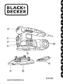
Black & Decker KA280 Manuale utente
- Categoria
- Trapani elettrici
- Tipo
- Manuale utente

67
8
1
2
3
4
5
9
KA280
www.blackanddecker.eu

2
English (Original instructions) 6
Deutsch (Übersetzung der ursprünglichen Anweisungen) 15
Français (Traduction des instructions initiales) 25
Italiano (Traduzione del testo originale) 34
Nederlands (Vertaling van de originele instructies) 43
Español (Traducción de las instrucciones originales) 52
Português (Tradução das instruções originais) 61
Svenska (Översättning av originalanvisningarna) 70
Norsk (Oversettelse av de opprinnelige instruksjonene) 79
Dansk (Oversættelse af de oprindelige instruktioner) 88
Suomi (Alkuperäisten ohjeiden käännös) 97
Ελληνικά (Μετάφραση των πρωτότυπων οδηγιών)105

3
10
A
B
C
D
E
5
5
12
10
11
4
6
F
14
13
11
15

4
20
19
19
21
20
9
19
20
7
8
7
8
22
G
H
IJ
K
L
180
17
16
7
18
17
8
20
19
16
17
19
20
19
21
20
16

5
23 11 20 19
3
M
N
O
P
Q
R
A
2
D
3
23 22
17
16
B
C
9
25
24
KA280L only

6
ENGLISH
ENGLISH
Intended use
Your BLACK+DECKER KA280 random orbital sander
has been designed for sanding wood, metal, plastics
and painted surfaces. This tool is intended for
consumer use only.
Safety instructions
General power tool safety warnings
Warning! Read all safety warnings and all
instructions. Failure to follow all instructions may
result in electric shock, fire and/or serious injury.
Save all warnings and instructions for future reference.
The term "power tool" in all of the warnings listed below
refers to your mains operated (corded) power tool or battery
operated (cordless) power tool.
1. Work area safety
a. Keep work area clean and well lit. Cluttered and dark
areas invite accidents.
b. Do not operate power tools in explosive
atmospheres, such as in the presence of flammable
liquids, gases or dust. Power tools create sparks
which may ignite the dust or fumes.
c. Keep children and bystanders away while operating
a power tool. Distractions can cause you to lose
control.
2. Electrical safety
a. Power tool plugs must match the outlet. Never
modify the plug in any way. Do not use any adapter
plugs with earthed (grounded) power tools.
Unmodified plugs and matching outlets will reduce risk
of electric shock.
b. Avoid body contact with earthed or grounded
surfaces such as pipes, radiators, ranges and
refrigerators. There is an increased risk of electric
shock if your body is earthed or grounded.
c. Do not expose power tools to rain or wet conditions.
Water entering a power tool will increase the risk of
electric shock.
d. Do not abuse the cord. Never use the cord for
carrying, pulling or unplugging the power tool.
Keep cord away from heat, oil, sharp edges or
moving parts. Damaged or entangled cords increase
the risk of electric shock.
e. When operating a power tool outdoors, use an
extension cord suitable for outdoor use. Use of a
cord suitable for outdoor use reduces the risk of electric
shock.
f. If operating a power tool in a damp location is
unavoidable, use a Residual Current Device (RCD)
protected supply. Use of an RCD reduces the risk of
electric shock.
3. Personal safety
a. Stay alert, watch what you are doing and use
common sense when operating a power tool. Do not
use a power tool while you are tired or under the
influence of drugs, alcohol or medication. A moment
of inattention while operating power tools may result in
serious personal injury.
b. Use personal protective equipment. Always wear
eye protection. Protective equipment such as dust
mask, non-skid safety shoes, hard hat, or hearing
protection used for appropriate conditions will reduce
personal injuries.
c. Prevent unintentional starting. Ensure the switch is
in the off-position before connecting to power
source and/or battery pack, picking up or carrying
the tool. Carrying power tools with your finger on the
switch or energising power tools that have the switch on
invites accidents.
d. Remove any adjusting key or wrench before turning
the power tool on. A wrench or a key left attached to
a rotating part of the power tool may result in personal
injury.
e. Do not overreach. Keep proper footing and balance
at all times. This enables better control of the power
tool in unexpected situations.
f. Dress properly. Do not wear loose clothing or
jewellery. Keep your hair, clothing and gloves away
from moving parts. Loose clothes, jewellery or long
hair can be caught in moving parts.
g. If devices are provided for the connection of dust
extraction and collection facilities, ensure these are
connected and properly used. Use of these devices
can reduce dust related hazards.
4. Power tool use and care
a. Do not force the power tool. Use the correct power
tool for your application. The correct power tool will do
the job better and safer at the rate for which it was
designed.
b. Do not use the power tool if the switch does not turn
it on and off. Any power tool that cannot be controlled
with the switch is dangerous and must be repaired.
c. Disconnect the plug from the power source and/or
the battery pack from the power tool before making
any adjustments, changing accessories, or storing
power tools. Such preventive safety measures reduce
the risk of starting the power tool accidentally.
!

7
ENGLISH
d. Store idle power tools out of the reach of children
and do not allow persons unfamiliar with the power
tool or these instructions to operate the power tool.
Power tools are dangerous in the hands of untrained
users.
e. Maintain power tools. Check for misalignment or
binding of moving parts, breakage of parts and any
other condition that may affect the power tools
operation. If damaged, have the power tool repaired
before use. Many accidents are caused by poorly
maintained power tools.
f. Keep cutting tools sharp and clean. Properly
maintained cutting tools with sharp cutting edges are
less likely to bind and are easier to control.
g. Use the power tool, accessories and tool bits etc.
in accordance with these instructions, taking into
account the working conditions and the work to be
performed. Use of the power tool for operations different
from those intended could result in a hazardous
situation.
5. Service
a. Have your power tool serviced by a qualified repair
person using only identical replacement parts. This
will make sure that the safety of the power tool is
maintained.
Additional power tool safety warnings
Hold the power tool by insulated gripping surfaces,
because the sanding belt / sanding base may
contact its own cord. Cutting a "live" wire may make
exposed metal parts of the power tool "live" could give
the operator an electric shock.
Use clamps or another practical way to secure and
support the workpiece to a stable platform. Holding
the work by hand or against your body leaves it unstable
and may lead to loss of control.
Warning! Contact with or inhalation of dust arising from
sanding applications may endanger the health of the
operator and possible bystanders. Wear a dust mask
specifically designed for protection against dust and
fumes and ensure that persons within or entering the
work area are also protected.
Thoroughly remove all dust after sanding.
Take special care when sanding paint which is possibly
lead based or when sanding some woods and metal
which may produce toxic dust:
- Do not let children or pregnant women enter the
work area.
- Do not eat, drink or smoke in the work area.
- Dispose of dust particles and any other debris safely.
The intended use is described in this instruction manual.
The use of any accessory or attachment or performance
of any operation with this tool other than those
recommended in this instruction manual may present
a risk of personal injury and/or damage to property.
Safety of others
This tool is not intended for use by persons (including
children) with reduced physical, sensory or mental
capabilities, or lack of experience and knowledge,
unless they have been given supervision or instruction
concerning the use of the appliance by a person
responsible for their safety.
Children should be supervised to ensure that they do
not play with the appliance.
Vibration
The declared vibration emission values stated in the
technical data and the declaration of conformity have been
measured in accordance with a standard test method
provided by EN 60745 and may be used for comparing one
tool with another. The declared vibration emission value may
also be used in a preliminary assessment of exposure.
Warning! The vibration emission value during actual use of
the power tool can differ from the declared value depending
on the ways in which the tool is used. The vibration level may
increase above the level stated.
When assessing vibration exposure to determine safety
measures required by 2002/44/EC to protect persons
regularly using power tools in employment, an estimation of
vibration exposure should consider, the actual conditions of
use and the way the tool is used, including taking account of
all parts of the operating cycle such as the times when the
tool is switched off and when it is running idle in addition to
the trigger time.
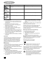
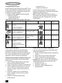
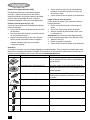
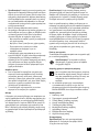
Labels on tools
The following pictograms are shown on the tool along with
the date code:
Electrical safety
If the supply cord is damaged, it must be replaced by the
manufacturer or an authorised BLACK+DECKER Service
Centre in order to avoid a hazard.
Warning! Additional safety warnings for sanders.
!
Warning! To reduce the risk of injury, the user
must read the instruction manual.
This tool is double insulated; therefore no earth wire
is required. Always check that the power supply
corresponds to the voltage on the rating plate.

8
ENGLISH
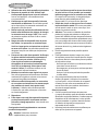
Features
1. On/off switch
2. Autoselect
®
dial
3. Base / speed setting indicator
4. Base release button
5. Random orbital sanding base
6. Large detail sanding base
7. Sanding base tip
8. Detail finger attachment
9. Dust canister
Assembly
Warning! Before assembly, make sure that the tool is
switched off and unplugged.
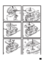
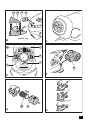
Removing sanding bases (fig. A)
To remove the sanding base, press the release
button (4) and pull the base (6) from the tool.
Attaching the random orbit sanding base (fig. B)
Hold the tool and the sanding base (5) facing upwards
as shown in fig. B.
Align the dust openings (10) in the sanding base with
the dust openings (11) in the tool base.
Press in on the sanding base until you hear it click into
place.
Fitting sanding sheets (fig. C)
Hold the tool with the sanding base (5) facing upwards.
Place the sanding sheet (12) onto the sanding base (5)
making sure that the holes in the sheet line up with the
holes in the base.
Large detail sanding base
With this sanding base, you can use the tool as a detail
sander or a flush sander.
Attaching the large detail sanding base (fig. D & E)
For detail sanding, the pointed end should face forward
(fig. D).
For sanding large areas, the pointed end should face to the
rear (fig. E).
Attach the sanding base as described above under
"Attaching the random orbit sanding base".
Press in on the sanding base until you hear it click into
place.
Fitting sanding sheets (fig. F)
Detach the two diamond-shaped tips (13) from the
sanding sheet (14).
Hold the tool with the sanding base facing upwards.
Place the sanding sheet (14) onto the sanding base,
making sure that the holes in the sheet line up with the
holes in the base.
The diamond-shaped tip (15) can be reversed and replaced
when worn.
When the front part of the tip is worn, detach it from the
sheet, reverse it and press it onto the sanding base
again.
When the whole tip is worn, remove it from the sanding
base and fit a new diamond shaped tip (13).
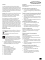
Tip of the sanding base (fig. G)
When the sanding base tip (7) is worn, it can be reversed
or replaced. When the diamond shaped tip holder (16) is
worn, it can be replaced. Spare parts are available from your
BLACK+DECKER dealer.
Remove the screw (17).
Reverse or replace the worn part.
Fit and tighten the screw (17).
Finger attachment (fig. H)
The finger attachment is used for fine detail sanding.
Remove the screw (17).
Remove the diamond-shaped tip holder (16) from the
sanding base.
Fit the finger attachment (8) onto the sanding base (6).
Fit and tighten the screw (17).
Fit the appropriate sanding sheet (18) onto the finger
attachment.
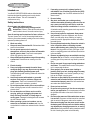
Profile attachment
The profile attachment is used for contour sanding.
Fitting the profile attachment (fig. I)
Remove the screw (17).
Remove the diamond-shaped tip holder (16) from the
sanding base.
Fit the profile attachment (19) onto the sanding base.
Fit and tighten the screw (17).
Fitting and removing a sanding profile (fig. J & K)
Choose the sanding profile most suitable for your
application.
Place one end of the sanding profile (20) into the recess
at the front end of the profile attachment (19).
Push the other end of the sanding profile until it clicks
into place.
To remove the sanding profile (20), push it forward and
pull the rear end out of the profile attachment (19).
Fitting a sanding sheet onto a sanding profile (fig. L)
Align the sanding sheet (21) with the sanding
profile (20).
Press the sanding sheet onto the sanding profile,
making sure that the sanding sheet follows the shape
of the profile.

9
ENGLISH
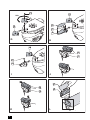
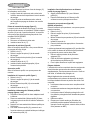
Louvre attachment (fig. M) (KA280L only)
With the louvre attachment you can work in crevices.
Remove the screw (17).
Remove the diamond-shaped tip holder (16) from the
sanding base.
Fit the louvre attachment (22) onto the sanding base.
Fit and tighten the screw.
Fit the appropriate sanding sheet onto the louvre
attachment.
The additional piece of hook and loop fastener (23) can be
attached to the top surface of the louvre attachment to allow
for sanding using both sides.
Remove the backing paper from the hook and loop
fastener (23).
Stick the hook and loop fastener to the top surface of the
louvre attachment (22).
Fit the sanding piece to the hook and loop fastener.
Residual risks
Additional residual risks may arise when using the tool which
may not be included in the enclosed safety warnings. These
risks can arise from misuse, prolonged use etc.
Even with the application of the relevant safety regulations
and the implementation of safety devices, certain residual
risks cannot be avoided. These include:
Injuries caused by touching any rotating/moving parts.
Injuries caused when changing any parts, blades or
accessories.
Injuries caused by prolonged use of a tool. When using
any tool for prolonged periods make sure you take
regular breaks.
Impairment of hearing.
Health hazards caused by breathing dust developed
when using your tool (example:- working with wood,
especially oak, beech and MDF).
Use
Warning! Let the tool work at its own pace. Do not overload.
Warning! Do not cover the ventilation slots when using the
tool. Hold the tool as shown in fig. R. Make sure that the
sanding base is flat on the workpiece.
Store the tool with a base in place.
Keep hands away from the spindle area on the tool.
Do not turn the Autoselect
®
dial while the unit is running.
Do not rest fingers on the base during use.
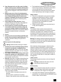
Switching on and off (fig. N)
To switch the tool on, set the on/off switch (1) to
position I.
To switch the tool off, set the on/off switch (1) to
position O.
Autoselect
®
Technology (fig.O)
This sander is fitted with an Autoselect
®
dial (2) which shows
various sanding applications. They are used to select the
correct operating mode for your particular sanding operation.
Using the Autoselect
®
dial (2), choose from one of the
following applications:
- Detail sanding (A).
- Corner sanding (B).
- Flush sanding (C).
- Random orbit sanding (D).
The correct base to be used and the recommended sanding
speed will be displayed in the base/speed setting
window (3).
Note: You can override the selected speed at any time by
moving the Autoselect
®
dial to positions (A) and (B), slower
speeds, or positions (C) and (D), higher speeds.

10
ENGLISH
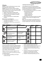
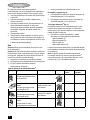
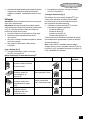
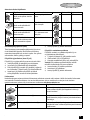
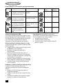
Autoselect
®
dial application chart
Automatic brake system (ABS)
This tool has an automatic brake system. When the tool is
not on the work surface, this feature keeps the speed of the
disc below the speed of the motor. When the tool is switched
off, the disc will stop very quickly.
Emptying the dust canister (fig. P & Q)
The dust canister (9) should be emptied after every ten
minutes of use.
Pull the dust canister (9) to the rear and off the tool.
Remove the cover (24) by twisting it counter clockwise.
Hold the dust canister (9) with the filter (25) facing down
and shake the canister to empty the contents. Shake the
cover (24) to empty the contents.
Refit the cover (24) onto the dust canister, twisting it
clockwise until it locks into place.
Refit the dust canister (9) onto the tool.
Cleaning the dust canister filter
The dust canister filter is re-usable and should be cleaned
regularly.
Empty the dust canister (9) as described above.
Pull the filter (25) off the dust canister.
Shake off excess dust by tapping the filter into a dustbin.
Warning! Do not brush or use compressed air or sharp
objects to clean the filter. Do not wash the filter.
Replace the filter (25).
Refit the cover (24).
Refit the dust canister (9) onto the tool.
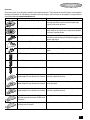
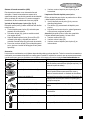
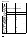
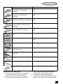
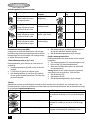
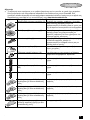
Accessories
The accessories supplied with your sander depend upon the model that you have purchased. All the accessories listed below
are available in our Piranha
®
range. If you require an accessory that is listed below but is not supplied with your sander please
visit our website at www.blackanddecker.eu.
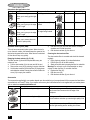
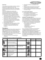
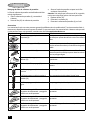
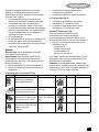
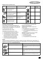
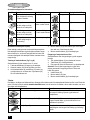
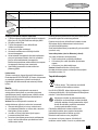
Setting Application Recommended base Base colour Speed setting
Small area sanding.
Allows you to easily get into tight
areas
Detail finger attachment Orange (1) Low
Large sanding.
Allows you to get up to the edge
of a 90° angle
Large detail base, tip facing
forward
Blue (1) Low
Flush sanding.
Allows you to get up to the edge
of a 90° angle
Flush sanding base,
90° edge facing forward.
Blue (2) High
Large area sanding.
Allows you to remove the most
amount of paint quickly.
Random orbit base Green (2) High
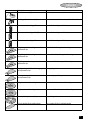
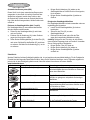
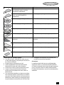
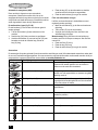
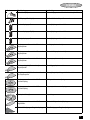
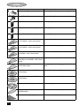
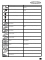
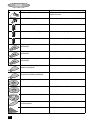
Item Description Purpose
Large detail sanding base (6). For medium to large areas. The large detail base can be
used to sand into corners and to the edge of the
workpiece.
Random orbit sanding base (5). For large areas. The random orbit base can be used for
curved surfaces and when you need a high-quality finish.
Detail finger (8). For small hard-to-reach areas. The detail finger can be
used for light sanding and for sanding into corners.

11
ENGLISH
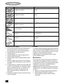
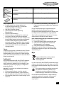
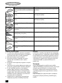
Louvre attachment (22). For intricate areas such as shutters and louvre doors.
Sanding profile attachment (19). An attachment to hold the various profiles listed below.
Concave curved sanding profile. For detailed sanding to suit this shape.
Convex curved sanding profile (20). For detailed sanding to suit this shape.
Pointed curved sanding profile. For detailed sanding to suit this shape.
240 grit large detail sanding sheet with two
replacement tips.
For a fine finish for large detail sanding.
120 grit large detail sanding sheet with two
replacement tips.
For a medium finish for large detail sanding.
60 grit large detail sanding sheet with two
replacement tips.
For a coarse finish for large detail sanding.
High-gloss large detail finish sheet (grey) with
two replacement tips.
For applying polish.
Cleaning sheet (red) for wood or metal with
two replacement tips.
For cleaning or polishing tasks on wood or metal.
240 grit random orbit sanding sheet. For a fine finish for random orbit sanding.
60 grit random orbit sanding sheet. For a coarse finish for random orbit sanding.
Round polishing bonnet (white). For polishing tasks.
120 grit detailed finger sanding sheet. For a medium finish for detailed sanding.
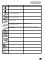
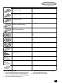
Item Description Purpose

12
ENGLISH
Hints for optimum use
For user comfort, the tool can be operated with one or
two hands (fig. R). Do not place your hands over the
ventilation slots.
Do not exert too much pressure on the tool.
Regularly check the condition of the sanding sheet.
Replace when necessary.
Always sand with the grain of the wood.
When sanding new layers of paint before applying
another layer, use extra fine grit.
On very uneven surfaces, or when removing layers of
paint, start with a coarse grit. On other surfaces, start
with a medium grit. In both cases, gradually change to
a fine grit for a smooth finish.
Consult your retailer for more information on available
accessories.
Accessories
The performance of your tool depends on the accessory
used. BLACK+DECKER and Piranha accessories are
engineered to high quality standards
and designed to
enhanc
e the performance of your tool. By using these
accessories you will get the very best from your tool.
Maintenance
Your BLACK+DECKER tool has been designed to operate over
a long period of time with a minimum of maintenance.
Continuous satisfactory operation depends upon proper tool
care and regular cleaning.
Warning! Before performing any maintenance on corded/
cordless power tools:
Switch off and unplug the appliance/tool.
Or switch off and remove the battery from the appliance/
tool if the appliance/tool has a separate battery pack.
Or run the battery down completely if it is integral and
then switch off.
Unplug the charger before cleaning it. Your charger
does not require any maintenance apart from regular
cleaning.
Regularly clean the ventilation slots in your appliance/tool/
charger using a soft brush or dry cloth.
Regularly clean the motor housing using a damp cloth.
Do not use any abrasive or solvent-based cleaner.
Regularly open the chuck and tap it to remove any dust from
the interior (when fitted).
Mains plug replacement (U.K. & Ireland only)
If a new mains plug needs to be fitted:
Safely dispose of the old plug.
Connect the brown lead to the live terminal in the
new plug.
Connect the blue lead to the neutral terminal.
Warning! No connection is to be made to the earth terminal.
Follow the fitting instructions supplied with good quality
plugs. Recommended fuse: 5 A.
Protecting the environment
Should you find one day that your BLACK+DECKER product
needs replacement, or if it is of no further use to you, do not
dispose of it with household waste. Make this product
available for separate collection.
Separate collection of used products and packaging
allows materials to be recycled and used again.
Re-use of recycled materials helps prevent
environmental pollution and reduces the demand
for raw materials.
Replacement louvre sanding sheet
attachment.
For attaching louvre sanding sheets.
60 grit louvre sanding sheet. For a course finish for louvre sanding.
120 grit louvre sanding sheet. For a medium finish for louvre sanding.
120 grit profile sanding sheet. For a medium finish for profile sanding.
Item Description Purpose
Separate collection. This product must not be
disposed of with normal household waste.

13
ENGLISH
Local regulations may provide for separate collection of
electrical products from the household, at municipal waste
sites or by the retailer when you purchase a new product.
BLACK+DECKER provides a facil
ity for the collection and
recycling of BLACK+DECKER prod
ucts once th
ey have
reached the end of
their working life. To take advantage of
this service please return your product to any authorised
repair agent who will collect them on our behalf.
You can check the location of your nearest authorised repair
agent by contacting your local BLACK+DECKER office at the
add
ress indicated
in this manual. Alternatively, a list of
authorised BLACK+DECKER repair a
gents an
d full details of
our after-sales se
rvice and contacts are available on the
Internet at: www.2helpU.com.
Technical data
Level of sound pressure according to EN 60745:
Sound pressure (L
pA
) 78.5 dB(A), uncertainty (K) 3 dB(A)
Sound power (L
WA
) 89.5 dB(A), uncertainty (K) 3 dB(A)
Vibration total values (triax vector sum)
according to EN 60745:
Vibration emission value (a
h
) 7,8 m/s
2
,
uncertainty (K) 1.5 m/s
2
EC declaration of conformity
MACHINERY DIRECTIVE
Th
e product has been used for trade, professional or
hire purposes.
The product has been subjected to misuse or neglect.
The product has sustained damage through foreign
objects, substances or accidents.
KA280 TYPE 1
Voltage Vac 230
Power input W 220
Orbits (no load) min-1 8500 / 13000
Oscillations
(no load)
min-1 17000 / 26000
Weight kg 1.9
♦
♦
♦
KA280 KA280L Random orbital sander
declares that these products described
under "technical data" are in compliance with:
2006/42/EC, EN60745-1:2009+A11:2010,
EN60745-2-4:2009+A11:2011
These products also comply with Directive 2014/30/EU an d
2011/65/EU.
For more information, please contact
following address or refer to the back of the manual.
The undersigned is responsible for compilation of the
technical file and makes this declaration on behalf of
at the
.
R. Laverick
Engineering Manager
Europe, 210 Bath Road, Slough
Berkshire, SL1 3YD
United Kingdom
18/11/2016
Guarantee
B is confident of the quality of its products and
offers an outstanding guarantee. This guarantee statement
is in addition to and in no way prejudices your statutory
rights. The guarantee is valid within the territories of the
Member States of the European Union and the European
Free Trade Area.
If a product becomes defective due to faulty
materials, workmanship or lack of conformity, within
2 4 months from the date of purchase,
guarantees to replace defective parts, repair products
subjected to fair wear and tear or replace such products to
make sure of the minimum inconvenience to the customer
unless:

14
ENGLISH
Repairs have been attempted by persons other than
authorised repair agents or Black & Decker service
staff.
To claim on the guarantee, you will need to submit proof of
purchase to the seller or an authorised repair agent. You can
check the location of your nearest authorised repair agent by
contacting your local Black & Decker office at the address
indicated in this manual. Alternatively, a list of authorised
Black & Decker repair agents and full details of our after-
sales service and contacts are available on the Internet at:
www.2helpU.com.
Please visit our website www.blackanddecker.co.uk to
register your new BLACK+DECKER product and to be kept
up to date on new products and special offers. Further
information on the BLACK+DECKER brand and our range of
products is available at www.blackanddecker.co.uk.

15
DEUTSCH
DEUTSCH
Bestimmungsgemäße Verwendung
Ihr BLACK+DECKER KA280 Exzenterschleifer ist zum
Schleifen von Holz, Metall, Kunststoff und lackierten
Oberflächen entwickelt. Dieses Gerät ist nicht für den
gewerblichen Einsatz vorgesehen.
Sicherheitshinweise
Allgemeine Sicherheitswarnungen für das Gerät
Achtung! Lesen Sie sämtliche
Sicherheitswarnungen und Anweisungen.
Die Nichteinhaltung der aufgeführten Anweisungen
kann einen elektrischen Schlag, Brand und/oder
schwere Verletzungen verursachen.
Bewahren Sie alle Sicherheitswarnungen und
Anweisungen gut auf.
Der im Folgenden verwendete Begriff „Gerät“ bezieht
sich auf netzbetriebene Geräte (mit Netzkabel) und auf
akkubetriebene Geräte (ohne Netzkabel).
1. Sicherheit im Arbeitsbereich
a. Halten Sie Ihren Arbeitsbereich sauber, und sorgen
Sie für ausreichende Beleuchtung. Unordnung und
das Arbeiten bei unzureichender Beleuchtung können
zu Unfällen führen.
b. Verwenden Sie die Geräte nicht in Umgebungen,
in denen Explosionsgefahr z. B. aufgrund von
brennbaren Flüssigkeiten, Gasen oder Staub
besteht. Geräte erzeugen Funken, die den Staub
oder die Dämpfe entzünden können.
c. Halten Sie Kinder und andere Personen während
der Benutzung eines Geräts fern. Vermeiden
Sie Ablenkungen, da Sie andernfalls die Kontrolle
verlieren können.
2. Elektrische Sicherheit
a. Der Netzstecker des Geräts muss in die Steckdose
passen. Der Stecker darf in keiner Weise verändert
werden. Verwenden Sie bei schutzgeerdeten
Geräten keine Adapterstecker. Unveränderte Stecker
und passende Steckdosen verringern das Risiko eines
elektrischen Schlags.
b. Vermeiden Sie Körperkontakt mit geerdeten
Oberflächen wie Rohren, Heizungen, Herden und
Kühlschränken. Es besteht ein erhöhtes Risiko eines
elektrischen Schlags, wenn Ihr Körper geerdet ist.
c. Schützen Sie das Gerät vor Regen und Nässe.
Das Eindringen von Wasser in ein Gerät erhöht
das Risiko eines elektrischen Schlags.
d. Verwenden Sie das Kabel ordnungsgemäß.
Verwenden Sie das Kabel niemals zum Tragen.
Trennen Sie das Gerät nicht durch Ziehen am Kabel
vom Netz. Halten Sie das Kabel fern von Hitze, Öl,
scharfen Kanten oder sich bewegenden Teilen.
Beschädigte oder verwickelte Kabel erhöhen das Risiko
eines elektrischen Schlags.
e. Verwenden Sie nur für den Außenbereich
zugelassene Verlängerungskabel, wenn Sie mit
dem Gerät im Freien arbeiten. Die Verwendung eines
für den Außenbereich geeigneten Verlängerungskabels
verringert das Risiko eines elektrischen Schlags.
f. Wenn ein Elektrowerkzeug in einer feuchten
Umgebung verwendet werden muss, schließen
Sie es unbedingt an eine Steckdose mit
Fehlerstromschutzschalter (FI-Schalter) an.
Ein Fehlerstromschutzschalter verringert das Risiko
eines elektrischen Schlags.
3. Sicherheit von Personen
a. Verwenden Sie das Gerät aufmerksam und
vernünftig. Benutzen Sie das Gerät nicht, wenn
Sie müde sind oder unter dem Einfluss von Drogen,
Alkohol oder Medikamenten stehen. Ein Moment der
Unachtsamkeit beim Gebrauch von Geräten kann zu
ernsthaften Verletzungen führen.
b. Verwenden Sie eine geeignete Schutzausrüstung.
Tragen Sie stets einen Augenschutz. Je nach Art und
Einsatz des Geräts verringert das Verwenden von
Schutzausrüstung wie Staubmasken, rutschfesten
Sicherheitsschuhen, Schutzhelmen oder Gehörschutz
das Risiko von Verletzungen.
c. Vermeiden Sie eine unbeabsichtigte
Inbetriebnahme. Vergewissern Sie sich, dass
das Gerät ausgeschaltet ist, bevor Sie es an
eine Steckdose oder einen Akku anschließen,
es hochheben oder tragen. Durch das Tragen des
Geräts mit dem Finger am Schalter oder durch das
Anschließen eingeschalteter Geräte können Unfälle
verursacht werden.
d. Entfernen Sie Einstell- oder Schraubenschlüssel,
bevor Sie das Gerät einschalten. Ein Schlüssel in
einem sich drehenden Teil kann zu Verletzungen
führen.
e. Beugen Sie sich nicht zu weit nach vorn über.
Achten Sie auf einen sicheren Stand, um in jeder
Arbeitsposition das Gleichgewicht zu halten.
Dadurch können Sie das Gerät in unerwarteten
Situationen besser unter Kontrolle halten.
!

16
DEUTSCH
f. Tragen Sie geeignete Kleidung. Tragen Sie
keine weite Kleidung oder Schmuck. Halten
Sie Haare, Kleidung und Handschuhe von sich
bewegenden Teilen fern. Weite Kleidung, Schmuck
oder lange Haare können von sich bewegenden Teilen
erfasst werden.
g. Falls Staubabsaug- und -fangvorrichtungen
vorhanden sind, vergewissern Sie sich, dass
diese angeschlossen sind und ordnungsgemäß
verwendet werden. Diese Vorrichtungen verringern
Gefährdungen durch Staub.
4. Gebrauch und Pflege von Geräten
a. Überlasten Sie das Gerät nicht. Verwenden Sie
für Ihre Arbeit das dafür bestimmte Gerät. Durch
das Arbeiten in dem für das Gerät angegebenen
Leistungsbereich erzielen Sie nicht nur optimale
Ergebnisse, Sie erhöhen auch die Sicherheit.
b. Verwenden Sie das Gerät nicht, wenn der
Ein-/Ausschalter nicht funktioniert. Ein Gerät,
das sich nicht mehr ein- oder ausschalten lässt, ist
gefährlich und muss repariert werden.
c. Ziehen Sie den Stecker aus der Steckdose, und/
oder trennen Sie das Gerät vom Akku, bevor Sie
Einstellungen vornehmen, Zubehörteile wechseln
oder das Gerät lagern. Diese Vorsichtsmaßnahme
verhindert den unbeabsichtigten Start des Geräts.
d. Bewahren Sie unbenutzte Geräte außerhalb der
Reichweite von Kindern auf. Lassen Sie Geräte
nicht von Personen benutzen, die damit nicht
vertraut sind oder diese Anweisungen nicht gelesen
haben. Geräte in den Händen von unerfahrenen
Personen sind gefährlich.
e. Halten Sie Geräte in einem einwandfreien Zustand.
Kontrollieren Sie, ob bewegliche Teile falsch
ausgerichtet sind oder klemmen und ob Teile
gebrochen oder so beschädigt sind, dass die
Funktion des Geräts beeinträchtigt ist. Lassen Sie
beschädigte Geräte vor dem Gebrauch reparieren.
Viele Unfälle werden durch schlecht gewartete Geräte
verursacht.
f. Halten Sie Schneidwerkzeuge scharf und sauber.
Sorgfältig gepflegte Schneidwerkzeuge mit scharfen
Schneidkanten verklemmen sich seltener und sind
leichter zu führen.
g. Verwenden Sie Gerät, Zubehör, Einsätze usw.
entsprechend diesen Anweisungen, und
berücksichtigen Sie dabei die Arbeitsbedingungen
und die auszuführende Arbeit. Der Gebrauch von
Geräten für andere als die vorgesehenen Zwecke
kann zu gefährlichen Situationen führen.
5. Service
a. Lassen Sie das Gerät nur von qualifiziertem
Fachpersonal und nur mit Originalersatzteilen
reparieren. So wird gewährleistet, dass die Sicherheit
des Geräts erhalten bleibt.
Zusätzliche Sicherheitswarnungen für das Gerät
Halten Sie das Gerät an den isolierten Griffflächen,
da das Schleifband/die Schleifplatte mit dem
Gerätekabel in Berührung kommen kann. Der
Kontakt mit stromführenden Leitungen setzt
möglicherweise offenliegende Metallteile am Gerät
unter Strom und kann einen Stromschlag verursachen.
Fixieren Sie das Werkstück mit Zwingen oder
ähnlichen Hilfsmitteln auf einer stabilen Oberfläche.
Wenn Sie das Werkstück nur mit den Händen halten
oder gegen Ihren Körper klemmen, können Sie leicht
die Kontrolle verlieren.
Achtung! Der beim Schleifen entstehende Staub kann
bei Berührung oder Einatmen zu gesundheitlichen
Schäden führen. Tragen Sie eine speziell für den
Schutz vor Staub und Dämpfen vorgesehene
Staubmaske, und stellen Sie sicher, dass auch andere
Personen geschützt sind, die den Arbeitsplatz betreten
oder sich dort aufhalten.
Entfernen Sie nach dem Schleifen sorgfältig alle
Staubreste.
Treffen Sie beim Schleifen von möglicherweise
bleihaltiger Farbe oder von bestimmten Holz- und
Metallarten, die giftigen Staub bilden können,
besondere Maßnahmen:
- Verhindern Sie, dass Kinder oder Schwangere
den Arbeitsplatz betreten.
- Essen, trinken und rauchen Sie nicht am Arbeitsplatz.
- Entsorgen Sie Staubteilchen und andere
Schleifabfälle sachgerecht.
Der vorgesehene Verwendungszweck ist in dieser
Anleitung beschrieben. Die Verwendung von Zubehör
oder Anbauteilen, die nicht in dieser Anleitung
empfohlen sind, sowie die Bedienung des Geräts in
Abweichung von den in dieser Anleitung beschriebenen
Verfahren kann zu Verletzungen und/oder
Sachschäden führen.
Achtung! Zusätzliche Sicherheitswarnungen für
Schleifgeräte.
!

17
DEUTSCH
Sicherheit anderer Personen
Dieses Gerät darf nicht von Personen (einschließlich
Kindern) mit eingeschränkten körperlichen,
sensorischen oder geistigen Fähigkeiten oder
mangelnder Erfahrung und Wissen in Bezug auf dessen
Gebrauch bedient werden, es sei denn, sie werden bei
der Verwendung des Geräts von einer erfahrenen
Person beaufsichtigt oder angeleitet.
Kinder müssen beaufsichtigt werden, um
sicherzustellen, dass sie nicht mit dem Gerät spielen.
Vibration
Die in den Abs
chnitten „Technische Daten“ und
„EU-Konformitätserklärung“ angegebenen Werte für die
Vibrationsemission wurden mit einer Standard-Prüfmethode
nach EN 60745 ermittelt und können zum Vergleich
verschiedener Geräte herangezogen werden. Außerdem
kann mit Hilfe dieser Werte die Belastung bei Verwendung
des Geräts schon im Voraus eingeschätzt werden.
Achtung! Die bei Verwendung des Geräts auftretende
Vibrationsemission ist von der Art des Gerätegebrauchs
abhängig und kann dementsprechend vom angegebenen
Wert abweichen. Gegebenenfalls kann die Vibration über
dem angegebenen Wert liegen.
Mit Hilfe der ermittelten Werte der Vibrationsbelastung durch
Elektrogeräte lassen sich Sicherheitsmaßnahmen festlegen,
die gemäß 2002/44/EG zum Schutz von Personen bestimmt
sind, die diese Geräte regelmäßig bei der Arbeit verwenden.
Bei der Einschätzung der Vibrationsbelastung sollten die
Gebrauchsumstände und die Art der Verwendung des
Geräts sowie alle Schritte des Arbeitszyklus berücksichtigt
werden. Dazu gehören Ruhe-, Leerlauf- und Startzeiten.
Warnsymbole am Gerät
Werden folgende Piktogramme auf das Werkzeug
zusammen mit dem Datum Code gezeigtt:
Elektrische Sicherheit
Ist das Netzkabel beschädigt, muss es durch den
Hersteller oder eine BLACK+DECKER Vertragswerkstatt
ausgetauscht werden, um eine mögliche Gefährdung zu
vermeiden.
Merkmale
1. Ein-/Ausschalter
2. Autoselect
®
-Programmwahl
3. Schleifplatten-/Geschwindigkeitseinstellungsanzeige
4. Schleifplattenentriegelungstaste
5. Exzenter-Schleifplatte
6. Große Dreieckschleifplatte
7. Schleifplattenspitze
8. Fingerschleifaufsatz
9. Staubfangbehälter
Montage
Achtung! Vergewissern Sie sich vor der Montage, dass das
Gerät ausgeschaltet ist und der Netzstecker gezogen wurde.
Entfernen der Schleifplatten (Abb. A)
Drücken Sie die Entriegelungstaste (4), und ziehen
Sie die Platte (6) vom Gerät ab, um die Schleifplatte
zu entfernen.
Anbringen der Exzenter-Schleifplatte (Abb. B)
Halten Sie das Gerät so fest, dass die Schleifplatte
(5) wie in Abb. B dargestellt nach oben weist.
Richten Sie die Stauböffnungen (10) der Schleifplatte
an den Stauböffnungen (11) an der Unterseite des
Geräts aus.
Drücken Sie auf die Schleifplatte, bis diese mit einem
Klicken einrastet.
Anbringen der Schleifblätter (Abb. C)
Halten Sie das Gerät so, dass die Schleifplatte (5) nach
oben weist.
Setzen Sie das Schleifblatt (12) auf der Schleifplatte
(5) auf. Achten Sie dabei darauf, dass die Löcher
im Schleifblatt mit den Löchern in der Schleifplatte
übereinstimmen.
Große Dreieckschleifplatte
Mit dieser Schleifplatte können Sie das Gerät als
Dreieckschleifer verwenden oder zwei Oberflächen
bündig schleifen.
Anbringen der großen Dreieckschleifplatte (Abb. D und E)
Bei kleinen Schleifbereichen sollte das spitze Ende nach
vorne weisen (Abb. D).
Bei großen Schleifbereichen sollte das spitze Ende nach
hinten weisen (Abb. E).
Bringen Sie die Schleifplatte wie oben unter „Anbringen
der Exzenter-Schleifplatte“ beschrieben an.
Drücken Sie auf die Schleifplatte, bis diese mit einem
Klicken einrastet.
Achtung! Lesen Sie vor Gebrauch die Anleitung
durch. Andernfalls besteht Verletzungsgefahr.
Dieses Gerät ist schutzisoliert, daher ist keine
Erdleitung erforderlich. Stellen Sie immer
sicher, dass die Netzspannung der Spannung
entspricht, die auf dem Typenschild des Geräts
angegeben ist.

18
DEUTSCH
Anbringen der Schleifblätter (Abb. F)
Trennen Sie die beiden rautenförmigen Spitzen (13)
vom Schleifblatt (14) ab.
Halten Sie das Gerät so, dass die Schleifplatte nach
oben weist.
Setzen Sie das Schleifblatt (14) auf die Schleifplatte auf.
Achten Sie dabei darauf, dass die Löcher im Schleifblatt
mit den Löchern in der Schleifplatte übereinstimmen.
Die rautenförmige Spitze (15) kann bei Verschleiß
umgedreht oder ausgetauscht werden.
Trennen Sie die Schleifspitze vom Schleifblatt, wenn
der Vorderteil der Schleifspitze verschlissen ist, drehen
Sie sie um, und drücken Sie sie wieder an die
Schleifplatte an.
Nehmen Sie die Spitze von der Schleifplatte ab, wenn
die gesamte Spitze verschlissen ist, und bringen Sie
eine neue rautenförmige Spitze (13) an.
Spitze der Schleifplatte (Abb. G)
Wenn die Spitze der Schleifplatte (7) verschlissen ist,
kann sie umgedreht oder ausgetauscht werden. Der
rautenförmige Spitzenhalter (16) kann bei Verschleiß
ausgetauscht werden. Ersatzteile erhalten Sie im
BLACK+DECKER Fachhandel.
Entfernen Sie die Schraube (17).
Drehen Sie das verschlissene Teil um, oder
tauschen Sie es aus.
Bringen Sie die Schraube (17) an, und ziehen Sie
diese fest.
Fingerschleifaufsatz (Abb. H)
Der Fingerschleifaufsatz wird für feine Schleifarbeiten
eingesetzt.
Entfernen Sie die Schraube (17).
Entfernen Sie den rautenförmigen Spitzenhalter
(16) von der Schleifplatte.
Bringen Sie den Fingerschleifaufsatz (8) an der
Schleifplatte (6) an.
Bringen Sie die Schraube (17) an, und ziehen
Sie diese fest.
Bringen Sie das entsprechende Schleifblatt (18)
am Fingerschleifaufsatz an.
Profilzubehör
Das Profilzubehör dient zum Schleifen von Konturen.
Anbringen des Profilzubehörs (Abb. I)
Entfernen Sie die Schraube (17).
Entfernen Sie den rautenförmigen Spitzenhalter (16)
von der Schleifplatte.
Bringen Sie das Profilzubehör (19) an der
Schleifplatte an.
Bringen Sie die Schraube (17) an, und ziehen Sie
diese fest.
Anbringen und Entfernen eines Schleifprofils
(Abb. J und K)
Wählen Sie das für Ihren Anwendungszweck am besten
geeignete Schleifprofil aus.
Setzen Sie das eine Ende des Schleifprofils (20)
in die Aussparung am vorderen Ende des
Profilzubehörs (19) ein.
Drücken Sie das andere Ende des Schleifprofils ein,
bis es hörbar einrastet.
Zum Entfernen des Schleifprofils (20) drücken Sie
dieses nach vorne und ziehen es gleichzeitig am
hinteren Ende aus dem Profilaufsatz (19).
Anbringen eines Schleifblatts an einem
Schleifprofil (Abb. L)
Richten Sie das Schleifblatt (21) am
Schleifprofil (20) aus.
Drücken Sie das Schleifblatt auf das Schleifprofil.
Achten Sie dabei darauf, dass das Schleifblatt mit
der Form des Profils übereinstimmt.
Lamellenschleifaufsatz (Abb. M, nur für KA280L)
Mit dem Lamellenschleifaufsatz können Sie in Fugen
arbeiten.
Entfernen Sie die Schraube (17).
Entfernen Sie den rautenförmigen Spitzenhalter (16)
von der Schleifplatte.
Bringen Sie den Lamellenschleifaufsatz (22) auf der
Schleifplatte an.
Bringen Sie die Schraube an, und ziehen Sie diese fest.
Bringen Sie das entsprechende Schleifblatt am
Lamellenschleifaufsatz an.
Die Klettverschlusshaftfläche (23) kann an der Oberseite
des Lamellenschleifaufsatzes angebracht werden, um das
Schleifen mit beiden Seiten zu ermöglichen.
Entfernen Sie das Trägerpapier von der
Klettverschlusshaftfläche (23).
Bringen Sie die Klettverschlusshaftfläche an der
Oberseite des Lamellenschleifaufsatzes (22) an.
Bringen Sie das Schleifblatt an der
Klettverschlusshaftfläche an.

19
DEUTSCH
Restrisiken
Für den Gebrauch dieses Geräts verbleiben zusätzliche
Restrisiken, die möglicherweise nicht in den
Sicherheitswarnungen genannt werden. Diese Risiken
bestehen beispielsweise bei Missbrauch oder längerem
Gebrauch.
Auch bei der Einhaltung der entsprechenden
Sicherheitsvorschriften und der Verwendung aller
Sicherheitsgeräte bestehen weiterhin bestimmte
Restrisiken. Diese werden im Folgenden aufgeführt:
Verletzungen, die durch das Berühren von sich
drehenden/bewegenden Teilen verursacht werden.
Verletzungen, die durch das Austauschen von Teilen,
Messern oder Zubehör verursacht werden.
Verletzungen, die durch längeren Gebrauch eines
Geräts verursacht werden. Legen Sie bei längerem
Gebrauch regelmäßige Pausen ein.
Beeinträchtigung des Gehörs.
Gesundheitsrisiken durch das Einatmen von Staub
beim Gebrauch des Geräts (Beispielsweise bei
Holzarbeiten, insbesondere Eiche, Buche und
Pressspan).
Verwendung
Achtung! Beschleunigen Sie den Arbeitsvorgang nicht mit
Gewalt. Vermeiden Sie eine Überlastung des Geräts.
Achtung! Bedecken Sie bei der Verwendung des Geräts
nicht die Lüftungsschlitze. Halten Sie das Gerät wie in
Abb. R dargestellt. Achten Sie darauf, dass die Schleifplatte
flach auf dem Werkstück aufliegt.
Lagern Sie das Gerät mit einer angebrachten
Schleifplatte.
Halten Sie Ihre Hände vom Spindelbereich des
Geräts fern.
Ändern Sie während dem Betrieb des Geräts nicht
die Einstellung der Autoselect
®
-Programmwahl.
Berühren Sie während des Gebrauchs die Schleifplatte
nicht mit den Fingern.
Ein- und Ausschalten (Abb. N)
Zum Einschalten des Geräts stellen Sie den
Ein-/Ausschalter (1) auf die Position I.
Zum Ausschalten des Geräts stellen Sie den
Ein-/Ausschalter (1) auf die Position O.
Autoselect
®
-Technologie (Abb. O)
Dieses Schleifgerät ist mit einer Autoselect
®
-Programmwahl
(2) für unterschiedliche Schleifanwendungen ausgestattet.
Die Programmwahl dient zum Auswählen des richtigen
Betriebsmodus für die entsprechende Schleifanwendung.
Wählen Sie über die Autoselect
®
-Programmwahl (2)
eine der folgenden Anwendungen aus:
- Dreieckschleifen (A)
- Eckschleifen (B)
- Bündigschleifen von Flächen (C)
- Exzenter-Schleifen (D)
Die zu verwendende Schleifplatte und die empfohlene
Schleifgeschwindigkeit werden im Fenster für die
Schleifplatten-/Geschwindigkeitseinstellung (3) angezeigt.
Note: Sie können die ausgewählte Geschwindigkeit
jederzeit ändern, indem Sie die Autoselect
®
-Programmwahl
für niedrigere Geschwindigkeiten in die Positionen (A) und
(B) und für höhere Geschwindigkeiten in die Positionen (C)
und (D) drehen.
Anwendungsdiagramm für die Autoselect
®
-Programmwahl
Einstellung Anwendungszweck Empfohlene Schleifplatte Farbe der
Schleifplatte
Geschwindigke
itseinstellung
Kleiner Schleifbereich.
Ermöglicht das problemlose
Schleifen von kleinen Bereichen.
Fingerschleifaufsatz Orange (1) Niedrig
Größere Schleifarbeiten.
Ermöglicht das Schleifen
eines Winkels von bis zu 90°
Große Dreieckschleifplatte,
Spitze nach vorne
Blau (1) Niedrig
Bündigschleifen.
Ermöglicht das Schleifen eines
Winkels von bis zu 90°
Platte zum Bündigschleifen,
90°-Kante nach vorne.
Blau (2) Hoch
Großer Schleifbereich.
Ermöglicht das schnelle
Abschleifen großer
Farbmengen.
Exzenter-Schleifplatte Grün (2) Hoch

20
DEUTSCH
Automatisches Bremssystem (ABS)
Dieses Gerät ist mit einem automatischen Bremssystem
ausgestattet. Ist das Gerät nicht auf die Oberfläche des
Werkstücks aufgesetzt, bewirkt diese Funktion, dass
die Drehzahl der Scheibe unter der Drehzahl des Motors
liegt. Wird das Gerät ausgeschaltet, hält die Scheibe sehr
schnell an.
Entleeren der Staubfangbehälter (Abb. P und Q)
Der Staubfangbehälter (9) muss während des Betriebs
alle zehn Minuten entleert werden.
Ziehen Sie den Staubfangbehälter (9) nach hinten
und vom Gerät ab.
Entfernen Sie die Abdeckung (24), indem Sie diese
gegen den Uhrzeigersinn drehen.
Halten Sie den Staubfangbehälter (9) mit dem Filter (25)
nach unten. Schütteln Sie den Behälter (25), um diesen
zu entleeren. Schütteln Sie die Abdeckung (24), um sie
zu entleeren.
Bringen Sie die Abdeckung (24) wieder an den
Staubfangbehälter an. Drehen Sie sie im Uhrzeigersinn,
bis sie einrastet.
Bringen Sie den Staubfangbehälter (9) wieder am
Gerät an.
Reinigen des Staubfangbehälterfilters
Der Staubfangbehälterfilter ist wieder verwendbar und muss
regelmäßig gereinigt werden.
Leeren Sie den Staubfangbehälter (9) wie oben
beschrieben.
Ziehen Sie den Filter (25) von dem
Staubfangbehälter ab.
Entfernen Sie den Staub, indem Sie den Filter
gegen die Innenseite des Abfalleimers klopfen.
Achtung! Reinigen Sie den Filter nicht mit einer Bürste,
einem scharfen Gegenstand oder mit Druckluft. Verwenden
Sie zur Reinigung keine Flüssigkeiten.
Bringen Sie den Filter (25) wieder an.
Bringen Sie die Abdeckung (24) wieder an.
Bringen Sie den Staubfangbehälter (9) wieder
am Gerät an.
Zubehörteile
Welches Zubehörteil mit dem Schleifgerät geliefert wird, ist vom jeweils erworbenen Modell abhängig. Für die Produktreihe
Piranha® sind alle folgenden Zubehörteile erhältlich. Wenn Sie ein Zubehörteil benötigen, das im Folgenden aufgeführt ist,
jedoch nicht mit dem Schleifgerät geliefert wurde, finden Sie weitere Informationen auf unserer Website
www.blackanddecker.eu.
Artikel Beschreibung Verwendungszweck
Große Dreieckschleifplatte (6) Für mittlere bis große Bereiche. Die große
Dreieckschleifplatte dient zum Schleifen von Ecken und
Kanten eines Werkstücks.
Exzenter-Schleifplatte (5) Für große Bereiche. Die Exzenter-Schleifplatte dient zum
Schleifen von gebogenen und qualitativ hochwertigen
Oberflächen.
Fingerschleifaufsatz (8) Für kleine, schwer zugängliche Bereiche. Der
Fingerschleifaufsatz dient zum leichten Schleifen sowie
zum Schleifen von Ecken.
Lamellenschleifaufsatz (22) Für schwierige Bereiche wie Fensterläden und
Lamellentüren
Schleifprofilaufsatz (19) Eine Halterung für die folgenden Profile.
Konkaves Schleifprofil Für den Detailschliff entsprechender Formen
La pagina si sta caricando...
La pagina si sta caricando...
La pagina si sta caricando...
La pagina si sta caricando...
La pagina si sta caricando...
La pagina si sta caricando...
La pagina si sta caricando...
La pagina si sta caricando...
La pagina si sta caricando...
La pagina si sta caricando...
La pagina si sta caricando...
La pagina si sta caricando...
La pagina si sta caricando...
La pagina si sta caricando...
La pagina si sta caricando...
La pagina si sta caricando...
La pagina si sta caricando...
La pagina si sta caricando...
La pagina si sta caricando...
La pagina si sta caricando...
La pagina si sta caricando...
La pagina si sta caricando...
La pagina si sta caricando...
La pagina si sta caricando...
La pagina si sta caricando...
La pagina si sta caricando...
La pagina si sta caricando...
La pagina si sta caricando...
La pagina si sta caricando...
La pagina si sta caricando...
La pagina si sta caricando...
La pagina si sta caricando...
La pagina si sta caricando...
La pagina si sta caricando...
La pagina si sta caricando...
La pagina si sta caricando...
La pagina si sta caricando...
La pagina si sta caricando...
La pagina si sta caricando...
La pagina si sta caricando...
La pagina si sta caricando...
La pagina si sta caricando...
La pagina si sta caricando...
La pagina si sta caricando...
La pagina si sta caricando...
La pagina si sta caricando...
La pagina si sta caricando...
La pagina si sta caricando...
La pagina si sta caricando...
La pagina si sta caricando...
La pagina si sta caricando...
La pagina si sta caricando...
La pagina si sta caricando...
La pagina si sta caricando...
La pagina si sta caricando...
La pagina si sta caricando...
La pagina si sta caricando...
La pagina si sta caricando...
La pagina si sta caricando...
La pagina si sta caricando...
La pagina si sta caricando...
La pagina si sta caricando...
La pagina si sta caricando...
La pagina si sta caricando...
La pagina si sta caricando...
La pagina si sta caricando...
La pagina si sta caricando...
La pagina si sta caricando...
La pagina si sta caricando...
La pagina si sta caricando...
La pagina si sta caricando...
La pagina si sta caricando...
La pagina si sta caricando...
La pagina si sta caricando...
La pagina si sta caricando...
La pagina si sta caricando...
La pagina si sta caricando...
La pagina si sta caricando...
La pagina si sta caricando...
La pagina si sta caricando...
La pagina si sta caricando...
La pagina si sta caricando...
La pagina si sta caricando...
La pagina si sta caricando...
La pagina si sta caricando...
La pagina si sta caricando...
La pagina si sta caricando...
La pagina si sta caricando...
La pagina si sta caricando...
La pagina si sta caricando...
La pagina si sta caricando...
La pagina si sta caricando...
La pagina si sta caricando...
La pagina si sta caricando...
La pagina si sta caricando...
La pagina si sta caricando...
-
 1
1
-
 2
2
-
 3
3
-
 4
4
-
 5
5
-
 6
6
-
 7
7
-
 8
8
-
 9
9
-
 10
10
-
 11
11
-
 12
12
-
 13
13
-
 14
14
-
 15
15
-
 16
16
-
 17
17
-
 18
18
-
 19
19
-
 20
20
-
 21
21
-
 22
22
-
 23
23
-
 24
24
-
 25
25
-
 26
26
-
 27
27
-
 28
28
-
 29
29
-
 30
30
-
 31
31
-
 32
32
-
 33
33
-
 34
34
-
 35
35
-
 36
36
-
 37
37
-
 38
38
-
 39
39
-
 40
40
-
 41
41
-
 42
42
-
 43
43
-
 44
44
-
 45
45
-
 46
46
-
 47
47
-
 48
48
-
 49
49
-
 50
50
-
 51
51
-
 52
52
-
 53
53
-
 54
54
-
 55
55
-
 56
56
-
 57
57
-
 58
58
-
 59
59
-
 60
60
-
 61
61
-
 62
62
-
 63
63
-
 64
64
-
 65
65
-
 66
66
-
 67
67
-
 68
68
-
 69
69
-
 70
70
-
 71
71
-
 72
72
-
 73
73
-
 74
74
-
 75
75
-
 76
76
-
 77
77
-
 78
78
-
 79
79
-
 80
80
-
 81
81
-
 82
82
-
 83
83
-
 84
84
-
 85
85
-
 86
86
-
 87
87
-
 88
88
-
 89
89
-
 90
90
-
 91
91
-
 92
92
-
 93
93
-
 94
94
-
 95
95
-
 96
96
-
 97
97
-
 98
98
-
 99
99
-
 100
100
-
 101
101
-
 102
102
-
 103
103
-
 104
104
-
 105
105
-
 106
106
-
 107
107
-
 108
108
-
 109
109
-
 110
110
-
 111
111
-
 112
112
-
 113
113
-
 114
114
-
 115
115
-
 116
116


Black & Decker KA280 Manuale utente
- Categoria
- Trapani elettrici
- Tipo
- Manuale utente
in altre lingue
- English: Black & Decker KA280 User manual
- français: Black & Decker KA280 Manuel utilisateur
- español: Black & Decker KA280 Manual de usuario
- Deutsch: Black & Decker KA280 Benutzerhandbuch
- Nederlands: Black & Decker KA280 Handleiding
- português: Black & Decker KA280 Manual do usuário
- dansk: Black & Decker KA280 Brugermanual
- svenska: Black & Decker KA280 Användarmanual
- suomi: Black & Decker KA280 Ohjekirja
Documenti correlati
-
Black & Decker BEW200 Manuale utente
-
BLACK DECKER KA300 Manuale del proprietario
-
Black & Decker KA330 Manuale utente
-
-
Black & Decker BEW230K Manuale utente
-
Black & Decker BDCDS18 Manuale utente
-
Black & Decker BEW210 Manuale utente
-
Black & Decker KA401L Manuale del proprietario
-
Black & Decker BDCROS18 Manuale utente
-
Black & Decker KA400 Manuale utente