
SLIDER
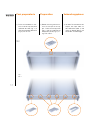
MOVEMENT
FLÄCHENBÜNDIGES
SCHIEBESYSTEM
MOVIMENTO
COMPLANARE
0% Cyan
64% Magenta
100% Yellow
0% Black
0% Cyan
0% Magenta
15% Yellow
82% Black
0% Cyan
0% Magenta
0% Yellow
37% Black

1
L’esclusività Exclusivity Exklusivität
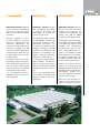
Bortoluzzi Sistemi progetta e
realizza soluzioni tecnologiche
per la chiusura e lo scorrimento
delle ante di mobili ed elementi
d’arredo.
Soluzioni standard e su misu-
ra sono sviluppate nel reparto
R&S da un gruppo di tecnici
altamente specializzato, per
mezzo di strutture informatiche
avanzate; i progetti sono poi
realizzati dal reparto produttivo,
secondo rigorosi criteri di orga-
nizzazione del lavoro e control-
lo della qualità.
Completa il processo un meto-
do innovativo di raccolta dell’or-
dine, effettuabile direttamente
dal sito internet dell’Azienda,
anche sulla base di specifiche
richieste del singolo cliente.
Dal 1987 Bortoluzzi Sistemi è
affidabilità tecnica, ed esclusi-
vità progettuale.
Bortoluzzi Sistemi designs
and manufactures technologi-
cal solutions for closing and
sliding doors on furniture and-
furnishing accessories.
Standard and custom solutions
are developed in the R&D de-
partment by a group of highly
specialized technicians us-
ing advanced computer tech-
nologies; the projects are then
created in the production de-
partment in accordance with
rigorous working organisation
and quality control criteria.
An innovative ordering proce-
dure completes the process,
directly through the company
website, also based on specific
requirements of each single cli-
ent.
Since 1987, Bortoluzzi Siste-
mi has been synonymous with
technical reliability, and exclu-
sive design.
Bortoluzzi Sistemi beschäf-
tigt sich mit Planung und Her-
stellung von technischen Lö-
sungen für das Schließen und
Gleiten von Türen für Möbel
und Einrichtungsgegenstände.
Standardlösungen und maßge-
schneiderte Lösungen werden
in der Abteilung F&E von einer
Gruppe hoch spezialisierter
Fachleute mit Hilfe der neu-
esten Computertechnik ent-
worfen. Anschließend werden
die Projekte von der Produkti-
onsabteilung hergestellt, nach
strengen Kriterien zu Arbeitsab-
läufen und Qualitätskontrolle.
Ergänzt wird dieser Prozess
durch eine innovative Art der
Bestellaufnahme, die direkt auf
der Website des Unternehmens
durchgeführt werden kann,
auch bei speziellen Wünschen
des einzelnen Kunden.
Seit 1987 steht Bortoluzzi Si-
stemi für technische Zuverläs-
sigkeit, und exklusive Planung.

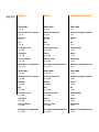
2
Slider M35
pag. 5
Caratteristiche tecniche
pag. 6
Brevetti
pag. 7
Kit
pag. 8
Legenda codici
pag. 10
Tipologie
pag. 11
Come ordinare
pag. 15
Montaggio e regolazioni
pag. 17
Slider M50
pag. 31
Caratteristiche tecniche
pag. 32
Brevetti
pag. 33
Kit
pag. 34
Legenda codici
pag. 36
Tipologie
pag. 37
Come ordinare
pag. 39
Montaggio e regolazioni
pag. 43
Indice
Slider M35
page 5
Technical features
page 6
Patent
page 7
Kit
page 8
Legend of codes
page 10
Types
page 11
How to order
page 15
Assembly and adjustments
page 17
Slider M50
page 31
Technical features
page 32
Patent
page 33
Kit
page 34
Legend of codes
page 36
Types
page 37
How to order
page 39
Assembly and adjustments
page 43
Slider M35
S. 5
Technische Eigenschaften
S. 6
Patent
S. 7
Kit
S. 8
Codelegende
S. 10
Typen
S. 11
Bestellung
S. 15
Montage und Regulierung
S. 17
Slider M50
S. 31
Technische Eigenschaften
S. 32
Patent
S. 33
Kit
S. 34
Codelegende
S. 36
Typen
S. 37
Bestellung
S. 39
Montage und Regulierung
S. 43
InhaltsverzeichnisIndex

3
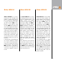
35
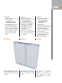
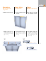
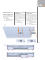
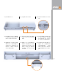
Slider M35/50 è un movi-
mento per ante complanari di
medie e grandi dimensioni e
pesi che possono raggiungere
i 50 Kg. Il meccanismo si rivol-
ge nella versione M35 a mo-
bili per la zona giorno e nella
versione M50 ad armadi per la
zona notte. Applicato sulla par-
te superiore delle strutture, per-
mette la realizzazione di mobili
a due ante o ad anta singola. I
pregi fondamentali del mecca-
nismo sono la silenziosità e la
fluidità dello scorrimento. Ogni
anta è provvista di un ammor-
tizzatore in apertura e di uno in
chiusura.
Il movimento è inoltre dotato di
una nuova copertura frontale,
che si presta ad essere perso-
nalizzata a piacere dal cliente.
Il meccanismo, nella versione
M50 standard, è adattabile a
contenitori con larghezze fino
a 200 mm superiori al mecca-
nismo.
The Slider M35/50 is a versa-
tile sliding mechanism for cabi-
net and wardrobe doors. The
Slider systems can support
medium to large sized doors up
to 50 kg in weight. The M35 is
designed for cabinets and the
M50 for bedroom wardrobes.
Applied to the top panel of the
structure, these sliders can be
used to create single or two-
door cabinets and wardrobes,
the major benefit of system
being the smooth and silent
movement of the doors. Each
door is equipped with a de-
celerating system that softens
both the opening and closing
phase.
The mechanism also features
a new front cover, which can
be customised to meet the cli-
ent’s preferences. The stand-
ard M50 can be adapted to fit
structures up to 200-mm wider
than the mechanism.
Slider M35/50 ist ein Schiebe-
system für Türen mittleren und
großen Maßes und mit Gewich-
ten bis zu 50 kg. Das System
der Version M35 eignet sich
für Möbel im Wohnbereich,
während die Version M50 für
Schlafzimmerschränke einge-
setzt wird. Der Beschlag wird
auf die Oberplatte montiert und
ermöglicht den Aufbau von ein-
oder zweitürigen Möbeln. Der
Mechanismus zeichnet sich
insbesondere durch seine ge-
räuscharme und hervorragen-
de Gleitfähigkeit aus. Alle Türen
haben eine gedämpfte Schlie-
ßung und Öffnung.
Das Schiebesystem ist zudem
mit einer neuen Frontabdeck-
leiste ausgestattet, die entspre-
chend dem Wunsch des Kun-
den gestaltet werden kann. Der
Mechanismus in der Standard
Version M50 kann bei Schrän-
ken, die bis 200 mm breiten als
der Beschlag selbst sind, ein-
gesetzt werden.
Slider M35/50 Slider M35/50 Slider M35/50

PANT.
166 C
0% Cyan
64% Magenta
100% Yellow
0% Black
PANT.
Black 7 C
0% Cyan
0% Magenta
15% Yellow
82% Black
PANT.
Cool gray
7
C
PANT.
158 U
PANT.
Black 7 U
PANT.
Cool gray
5
U
0% Cyan
0% Magenta
0% Yellow
37% Black

6
Composizione movimenti
●
Profili in alluminio: lega 6060T5
anodizzati argento ARC10
●
Ruote di scorrimento:
cuscinetti per alta velocità
rivestiti in materiale plastico
●
Guide per l’uscita delle ante:
in materiale plastico per una
ottimale insonorizzazione
●
Carrelli di scorrimento:
in lamiera verniciata e zincata
●
Componenti di traslazione
e regolazione:
in zama primaria 15
Caratteristiche delle ante
●
Peso massimo per singola
anta = 35 Kg
(uniformemente distribuito)
●
Larghezza:
- minima 600 mm
- massima 2000 mm
●
Altezza: massima 2200 mm
●
Spessore:
- con regolatore superiore
incassato minimo 18 mm,
massimo 45 mm
(maniglia compresa);
- con regolatore superiore
esterno minimo 18 mm,
massimo 40 mm
(maniglia compresa).
●
Regolazione verticale
dell'anta ± 5 mm
●
Regolazione orizzontale
dell'anta ± 3.5 mm
(per eventuali meccanismi
fuori misura, contattare
la Bortoluzzi Sistemi).
Caratteristiche
tecniche
Technical
features
Technische
Eigenschaften
Mechanism elements
●
ARC10 silver anodised
6060T5 aluminium alloy
profiles
●
Nylon-coated rollers with high
velocity bearings
●
Thermoplastic guide rails for
excellent sound-proofing
●
Slide brackets in galvanised
steel
●
Sliders and adjusters in
primary Zamak 15
Door features
●
Maximum weight for each
door = 35 kg
(Evenly distributed)
●
Width:
- minimum 600 mm
- maximum 2000 mm
●
Height: maximum 2200 mm
●
Thickness:
- with upper adjusters
recessed
minimum 18 mm,
maximum 45 mm
(including handle);
- with surface mounted upper
adjusters
minimum 18 mm,
maximum 40 mm
(including handle).
●
Door vertical adjustment
± 5 mm
●
Door horizontal adjustment
± 3.5 mm
(For mechanisms out of the
range contact Bortoluzzi
Sistemi).
Zusammensetzung
der Beschläge
●
Aluprofil: aus Aluminium
Legierung 6060T5, eloxiert Silber
ARC10
●
Schieberollen:
mit Hochgeschwindigkeitslagern
und kunststoffüberzogen
●
Türgleitschienen:
Aus Kunststoffmaterial für eine
optimale Geräuschdämmung
●
Laufwagen: aus verzinktem
und lackiertem Blech
●
Einstell- und
Verschiebungselemente:
aus 15er Zamakdruckguss
Eigenschaften der Türen
●
Max. Gewicht je Tür = 35 Kg
(Gleichmäßig verteilt)
●
Breite: min. 600 mm
max. 2000 mm
●
Höhe: max. 2200 mm
●
Stärke:
- mit eingebautem oberen
Ausrichtungsbeschlag
min. 18 mm, max. 45 mm
(inkl. Griff);
- mit externem oberen
Ausrichtungsbeschlag
min. 18 mm, max. 40 mm
(inkl. Griff).
●
Vertikal Regulierung des Blattes
± 5 mm
●
Horizontale Regulierung des
Blattes ± 3.5 mm
(Bei Systemen außerhalb
dieser Maße Bortoluzzi Sistemi
kontaktieren).

7
35
Brevetto depositato presso il
Ministero delle Attività Produttive
Ufficio Italiano Brevetti e Marchi
(U.I.B.M.).
Patent filed with the Ministry
of Productive Activities - Italian
Patent and Trademark Office
(U.I.B.M.).
Das Patent ist bei dem
Ministerium für Industrie,
Handel und Handwerk auf
dem Italienischen Patent-
und Markenamt (U.I.B.M.)
hinterlegt.
Brevetti Patent Patent
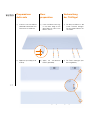
●
Materiale:
a) legno o derivati;
b) vetro con telaio in alluminio
(per verificare
la fattibilità contattare la
Bortoluzzi Sistemi).
●
Sono disponibili meccanismi
per l'apertura di due ante
complanari uguali oppure di
un’unica anta complanare su
anta battente o vano a giorno.
●
L’apertura delle ante è prevista
tramite l’ausilio di maniglie
posizionate al centro del
mobile.
●
Materials:
a) wood or derivatives;
b) glass with aluminium frame
(for feasibility contact
Bortoluzzi Sistemi).
●
Mechanisms are available for
the opening of two identical
sliding doors, or a single
sliding door paired with a
hinged door or an open
compartment.
●
The doors can be opened
with the use of handles placed
in the centre of the cabinet
or wardrobe.
●
Material:
a) Holz oder Holzprodukte;
b) Glas mit Alurahmen
(für die Machbarkeit
Bortoluzzi Sistemi
kontaktieren).
●
Verfügbar sind
Öffnungsmechanismen mit
Öffnung von zwei gleichbreiten
flächenbündigen Türen
oder einer flächenbündigen
Einzeltür an Drehtür oder
offenem Element.
●
Die Öffnung der Türflügel
erfolgt mithilfe von in der
Mitte des Möbelstücks
positionierten Griffen.

8
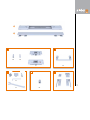
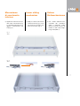
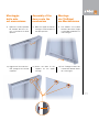
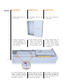
Il cliente riceverà
una scatola contenente:
1
n. 1 binario superiore
di scorrimento
completo di carrelli
2
n. 1 binario inferiore
di scorrimento
completo di carrelli
PER OGNI ANTA
A
n. 1 regolatore verticale
e orizzontale;
n. 1 regolatore verticale;
n. 4 bussole in zama
M6x23;
n. 4 viti speciali TE M6x22.
B
n. 2 distanziali per regolatori
esterni.
PER OGNI MECCANISMO
C
n. 1 chiave esagonale
4 mm;
n. 1 chiave fissa 10 mm;
n. 4 paracolpi autoadesivi;
n. 4 paracolpi a fungo;
n. 4 viti TCEI M5x16.
D
n. 2 bussole M6x13.
LA QUANTITÀ DEGLI
ELEMENTI SOTTO ELENCATI,
DIPENDE DAL MECCANISMO
E
- Clip profilo superiore;
- Clip profilo inferiore.
Kit Kit Kit
The client will receive a
box containing:
1
1 no. top slider rail
complete with carriages
2
1 no. bottom slider rail
complete with carriages
FOR EACH DOOR
A
1 no. horizontal and vertical
adjuster;
1 no. vertical adjuster;
4 no. M6x23 Zamak
bushings;
4 no. special TE
M6x22screws;
B
2 no. spacers for external
adjusters.
FOR EACH MECHANISM
C
1 no. 4 mm hexagonal key;
1 no. 10 mm spanner;
4 no. self-adhesive buffers;
4 no. buffer heads;
4 no. M5x16 TCEI screws.
D
2 no. M6x13 bushings.
THE QUANTITY OF THE
FOLLOWING COMPONENTS
WILL VARY DEPENDING ON
THE MECHANISM.
E
- Upper profile clip;
- Lower profile clip.
Dem Kunden wird eine
Packung mit folgendem
Material geliefert:
1
n. 1 obere Schiene
komplett mit Laufwagen
2
n. 1 untere Schiene komplett
mit Laufwagen
FÜR JEDE TÜR
A
n. 1 Waagrecht-
Senkrecht-
Ausrichtbeschlag;
n. 1 Senkrecht-
Ausrichtbeschlag;
n. 4 Zamak Buchsen
M6x23;
n. 4 Spezial-
Sechskantschrauben
TE M6x22.
B
n. 2 Abstandhalter für
externe
Ausrichtbeschläge.
FÜR JEDEN MECHANISMUS
C
n. 1 Sechskantschlüssel
4 mm;
n. 1 Maulschlüssel 10 mm;
n. 4 selbsthaftende Puffer;
n. 4 Gummipuffer;
n. 4 TCEI Schrauben
M5x16.
D
n. 2 Buchsen M6x13.
DIE ANZAHL DER UNTEN
AUFGEFÜHRTEN ELEMENTE
IST VOM BESCHLAG
ABHÄNGIG
E
- Clips für oberes Profil;
- Clips für unteres Profil.

9
35
1
2
A
E
B
C D
x 1
x 1
x 4 x 4
x 1
x 1
x 4x 1x 4
x 2
x 2

10
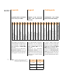
LT LA HT HI HA SPA SPAM SPB SPC SPE SPI SAE AA DYPL DXPL RAS RM REG
Larghezza totale mobile (mm)
Total width of cabinet (mm)
Gesamtes Schrankkorpusbreitenmass (mm)
Larghezza anta (mm)
Width of door (mm)
Türbreite (mm)
Altezza totale mobile (mm)
Total height of exterior of cabinet (mm)
Gesamtes Schrankkorpushöhenmass (mm)
Altezza vano interno mobile (mm)
Height of interior of cabinet (mm)
Innen Schrankkorpushöhe (mm)
Altezza anta (mm)
Height of door (mm)
Türhöhe (mm)
Spessore anta (mm)
Thickness of door (mm)
Türstärke (mm)
Spessore anta + maniglia (mm)
Thickness of door + handle (mm)
Türstärke + Griff (mm)
Spessore base (mm)
Thickness of bottom panel (mm)
Untere Korpusplattenstärke (mm)
Spessore cielo (mm)
Thickness of top panel (mm)
Obere Korpusplattenstärke (mm)
Spessore spalla esterna (mm)
Thickness of side panel (mm)
Seiten Korpusstärke (mm)
Spessore spalla centrale (mm)
Thickness of centre panel (mm)
Mittelseite Korpusstärke (mm)
Sormonto anta su spalla esterna (mm) (Tip. A)
Superimposition of door on side panel (mm) (Tip. A) Tür vor
Aussenseiten (mm) (Tip. A)
Distanza spalla centrale-anta in apertura (mm)
Central shoulder-wing distance when open (mm)
Abstand Mittelstruktur geöffneter Türflügel (mm)
Distanza base-piedino in profondità (mm)
Base-foot depth distance (mm)
Abstand Basis-Stellfuß in Tiefe (mm)
Ingombro piedino dal fianco laterale (mm)
Space for foot from side panel (mm)
Raumbedarf Stellfuß ab Seitenwand (mm)
Rientro anta dalla struttura (mm) (Tip. B)
Space between door and structure (mm) (Type B)
Türabstand von Korpus (mm) (Typ. B)
Rientro maniglia dal bordo anta (mm)
Space between handle and door edge (mm)
Griffabstand von seitlicher Kante (mm)
Regolatori superiori esterni (EST.) o incassati (INC.)
Upper external (EST.) or mounted (INC.) adjustment elements
Obere Ausrichtbeschläge, extern (EST.) oder eingebaut (INC.)
LI
(mm)
DXPL max
(mm)
LI< 1550 190
1550≤LI< 1750 100
LI≥ 1750 125
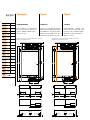
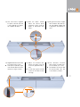
Legenda
Legenda codici e specifiche
necessarie per l’ordine.
Nella tabella sono indicate le va-
riabili riguardanti la progettazione
del contenitore sul quale appli-
care la tipologia di Slider M35
prescelta.
Sulla base di tali informazioni,
Bortoluzzi Sistemi fornirà gli
elaborati riguardanti le lavorazioni
da eseguire su struttura ed ante.
CodelegendeLegend
Legend of the necessary
codes and specifications
for order.
Codelegende und nötige
Details für die Bestellung.
This table provides the design
parameters for the cabinet or
structure on which the selected
type of Slider M35 will be-
mounted.
Based on this information,
Bortoluzzi Sistemi will pro-
vide detailed information on the
drilling and machining require-
ments for the furniture panels
and doors.
In dieser Tabelle werden die
Variablen zum Entwurf des Mö-
belstücks (Korpus) angegeben,
in dem das ausgewählte Slider
M35 eingesetzt werden soll.
Auf der Grundlage dieser Infor-
mationen wird Bortoluzzi Sis-
temi Zeichnungen über die an
den Möbelbauteilen vorzuneh-
menden Bearbeitungen liefern.
*
Ingombro piedino dal fianco laterale
Space for foot from side panel
Raumbedarf Stellfuß ab Seitenwand
*
DXPL

Slider M35 tipologia A27
regolatori esterni
Slider M35 tipologia A27
regolatori incassati
SPAM
Max 40 mm
HA
HI
SPC
SPB
54
HT
SPA
SPAM
Max 45 mm
HA
HI
SPC
SPB
54
HT
SPE SPESPI
LT
RM RM SAESAE
LA LA
4
AA
SPE SPESPI
LT
RM RM SAESAE
LA LA
4
AA
266
223.5
3150 150 3
27 27
54
212.5*
255*
DXPL
DYPL
DXPL
DYPL
Min 150 mm
DXPL
DYPL
DXPL
DYPL
Min 150 mm
SPA
22.5
Min
60 mm
Min
60 mm
22.5
54
Slider M35 tipologia A43
regolatori esterni
Slider M35 tipologia A43
regolatori incassati
SPAM
Max 40 mm
HA
HI
SPC
SPB
54
HT
SPA
SPAM
Max 45 mm
HA
HI
SPC
SPB
54
HT
SPE SPESPI
LT
RM RM SAESAE
LA LA
4
AA
SPE SPESPI
LT
RM RM SAESAE
LA LA
4
AA
266
223.5
54
212.5*
255*
DXPL
DYPL
DXPL
DYPL
Min 150 mm
DXPL
DYPL
DXPL
DYPL
Min 150 mm
SPA
Min
60 mm
Min
60 mm
54
150 3
43
12.5
150 3
43
12.5
55 55 55 55
24
Min
60 mm
24
Min
60 mm
24 24
Min
60 mm
Min
60 mm
Piedino laterale
Lateral foot
Seitlicher Stellfuß
Piedino laterale
Lateral foot
Seitlicher Stellfuß
Piedino centrale
Central foot
Zentraler Stellfuß
Piedino laterale
Lateral foot
Seitlicher Stellfuß
Piedino laterale
Lateral foot
Seitlicher Stellfuß
Piedino centrale
Central foot
Zentraler Stellfuß
Piedino laterale
Lateral foot
Seitlicher Stellfuß
Piedino laterale
Lateral foot
Seitlicher Stellfuß
Piedino centrale
Central foot
Zentraler Stellfuß
Piedino laterale
Lateral foot
Seitlicher Stellfuß
Piedino laterale
Lateral foot
Seitlicher Stellfuß
Piedino centrale
Central foot
Zentraler Stellfuß
Slider M35 tipologia A27
regolatori esterni
Slider M35 tipologia A27
regolatori incassati
SPAM
Max 40 mm
HA
HI
SPC
SPB
54
HT
SPA
SPAM
Max 45 mm
HA
HI
SPC
SPB
54
HT
SPE SPESPI
LT
RM RM SAESAE
LA LA
4
AA
SPE SPESPI
LT
RM RM SAESAE
LA LA
4
AA
266
223.5
3150 150 3
27 27
54
212.5*
255*
DXPL
DYPL
DXPL
DYPL
Min 150 mm
DXPL
DYPL
DXPL
DYPL
Min 150 mm
SPA
22.5
Min
60 mm
Min
60 mm
22.5
54
Slider M35 tipologia A43
regolatori esterni
Slider M35 tipologia A43
regolatori incassati
SPAM
Max 40 mm
HA
HI
SPC
SPB
54
HT
SPA
SPAM
Max 45 mm
HA
HI
SPC
SPB
54
HT
SPE SPESPI
LT
RM RM SAESAE
LA LA
4
AA
SPE SPESPI
LT
RM RM SAESAE
LA LA
4
AA
266
223.5
54
212.5*
255*
DXPL
DYPL
DXPL
DYPL
Min 150 mm
DXPL
DYPL
DXPL
DYPL
Min 150 mm
SPA
Min
60 mm
Min
60 mm
54
150 3
43
12.5
150 3
43
12.5
55 55 55 55
24
Min
60 mm
24
Min
60 mm
24 24
Min
60 mm
Min
60 mm
Piedino laterale
Lateral foot
Seitlicher Stellfuß
Piedino laterale
Lateral foot
Seitlicher Stellfuß
Piedino centrale
Central foot
Zentraler Stellfuß
Piedino laterale
Lateral foot
Seitlicher Stellfuß
Piedino laterale
Lateral foot
Seitlicher Stellfuß
Piedino centrale
Central foot
Zentraler Stellfuß
Piedino laterale
Lateral foot
Seitlicher Stellfuß
Piedino laterale
Lateral foot
Seitlicher Stellfuß
Piedino centrale
Central foot
Zentraler Stellfuß
Piedino laterale
Lateral foot
Seitlicher Stellfuß
Piedino laterale
Lateral foot
Seitlicher Stellfuß
Piedino centrale
Central foot
Zentraler Stellfuß
11
35
COD. mm
LT
●
LA
●
HT
●
HI
●
HA
●
SPA
●
SPAM
●
SPB
●
SPC
●
SPE
●
SPI
●
SAE
●
AA
●
DYPL
●
DXPL
●
RAS
RM
●
REG
❏ EST.
❏ INC.
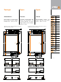
Tipologie
TIPOLOGIA A27
Ante a ridosso su cielo, base e
fianchi laterali. Distanza “bordo
inferiore ante” - “base” 27 mm.
TYPE A27
The doors covering both top,
bottom and side panels. The
Distance between the lower
edge of door and the bottom
panel is 27 mm.
TYP A27
Aufschlagende Fronten am
Korpus. Abstand "Front-Unter-
kante" - "Basis" 27 mm
Types Typen
Regolatori incassati - Mounted adjustment elements
Eingebaute Ausrichtbeschläge
Regolatori esterni - External adjustment elements
Externe Ausrichtbeschläge
*Con telaio Clipper + 6 mm
*With Clipper frame + 6 mm
*Mit Clipper Beschlager + 6 mm

12
COD. mm
LT
●
LA
●
HT
●
HI
●
HA
●
SPA
●
SPAM
●
SPB
●
SPC
●
SPE
●
SPI
●
SAE
●
AA
●
DYPL
●
DXPL
●
RAS
RM
●
REG
❏ EST.
❏ INC.
Slider M35 tipologia A27
regolatori esterni
Slider M35 tipologia A27
regolatori incassati
SPAM
Max 40 mm
HA
HI
SPC
SPB
54
HT
SPA
SPAM
Max 45 mm
HA
HI
SPC
SPB
54
HT
SPE SPESPI
LT
RM RM SAESAE
LA LA
4
AA
SPE SPESPI
LT
RM RM SAESAE
LA LA
4
AA
266
223.5
3150 150 3
27 27
54
212.5*
255*
DXPL
DYPL
DXPL
DYPL
Min 150 mm
DXPL
DYPL
DXPL
DYPL
Min 150 mm
SPA
22.5
Min
60 mm
Min
60 mm
22.5
54
Slider M35 tipologia A43
regolatori esterni
Slider M35 tipologia A43
regolatori incassati
SPAM
Max 40 mm
HA
HI
SPC
SPB
54
HT
SPA
SPAM
Max 45 mm
HA
HI
SPC
SPB
54
HT
SPE SPESPI
LT
RM RM SAESAE
LA LA
4
AA
SPE SPESPI
LT
RM RM SAESAE
LA LA
4
AA
266
223.5
54
212.5*
255*
DXPL
DYPL
DXPL
DYPL
Min 150 mm
DXPL
DYPL
DXPL
DYPL
Min 150 mm
SPA
Min
60 mm
Min
60 mm
54
150 3
43
12.5
150 3
43
12.5
55 55 55 55
24
Min
60 mm
24
Min
60 mm
24 24
Min
60 mm
Min
60 mm
Piedino laterale
Lateral foot
Seitlicher Stellfuß
Piedino laterale
Lateral foot
Seitlicher Stellfuß
Piedino centrale
Central foot
Zentraler Stellfuß
Piedino laterale
Lateral foot
Seitlicher Stellfuß
Piedino laterale
Lateral foot
Seitlicher Stellfuß
Piedino centrale
Central foot
Zentraler Stellfuß
Piedino laterale
Lateral foot
Seitlicher Stellfuß
Piedino laterale
Lateral foot
Seitlicher Stellfuß
Piedino centrale
Central foot
Zentraler Stellfuß
Piedino laterale
Lateral foot
Seitlicher Stellfuß
Piedino laterale
Lateral foot
Seitlicher Stellfuß
Piedino centrale
Central foot
Zentraler Stellfuß
Slider M35 tipologia A27
regolatori esterni
Slider M35 tipologia A27
regolatori incassati
SPAM
Max 40 mm
HA
HI
SPC
SPB
54
HT
SPA
SPAM
Max 45 mm
HA
HI
SPC
SPB
54
HT
SPE SPESPI
LT
RM RM SAESAE
LA LA
4
AA
SPE SPESPI
LT
RM RM SAESAE
LA LA
4
AA
266
223.5
3150 150 3
27 27
54
212.5*
255*
DXPL
DYPL
DXPL
DYPL
Min 150 mm
DXPL
DYPL
DXPL
DYPL
Min 150 mm
SPA
22.5
Min
60 mm
Min
60 mm
22.5
54
Slider M35 tipologia A43
regolatori esterni
Slider M35 tipologia A43
regolatori incassati
SPAM
Max 40 mm
HA
HI
SPC
SPB
54
HT
SPA
SPAM
Max 45 mm
HA
HI
SPC
SPB
54
HT
SPE SPESPI
LT
RM RM SAESAE
LA LA
4
AA
SPE SPESPI
LT
RM RM SAESAE
LA LA
4
AA
266
223.5
54
212.5*
255*
DXPL
DYPL
DXPL
DYPL
Min 150 mm
DXPL
DYPL
DXPL
DYPL
Min 150 mm
SPA
Min
60 mm
Min
60 mm
54
150 3
43
12.5
150 3
43
12.5
55 55 55 55
24
Min
60 mm
24
Min
60 mm
24 24
Min
60 mm
Min
60 mm
Piedino laterale
Lateral foot
Seitlicher Stellfuß
Piedino laterale
Lateral foot
Seitlicher Stellfuß
Piedino centrale
Central foot
Zentraler Stellfuß
Piedino laterale
Lateral foot
Seitlicher Stellfuß
Piedino laterale
Lateral foot
Seitlicher Stellfuß
Piedino centrale
Central foot
Zentraler Stellfuß
Piedino laterale
Lateral foot
Seitlicher Stellfuß
Piedino laterale
Lateral foot
Seitlicher Stellfuß
Piedino centrale
Central foot
Zentraler Stellfuß
Piedino laterale
Lateral foot
Seitlicher Stellfuß
Piedino laterale
Lateral foot
Seitlicher Stellfuß
Piedino centrale
Central foot
Zentraler Stellfuß
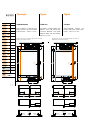
Regolatori incassati - Mounted adjustment elements
Eingebaute Ausrichtbeschläge
Regolatori esterni - External adjustment elements
Externe Ausrichtbeschläge
*Con telaio Clipper + 6 mm
*With Clipper frame + 6 mm
*Mit Clipper Beschlager + 6 mm
Tipologie Types Typen
TIPOLOGIA A43
Ante a ridosso su cielo, base e
fianchi laterali. Distanza “bordo
inferiore ante” - “base” 43 mm.
TYPE A43
The doors covering both top,
bottom and side panels.The
Distance between the lower
edge of door and the bottom
panel is 43 mm.
TYP A43
Aufschlagende Fronten am
Korpus. Abstand "Front-Unter-
kante" - "Basis" 43 mm.

Slider M35 tipologia B27
regolatori esterni
Slider M35 tipologia B27
regolatori incassati
SPAM
max 40 mm
HA
HI
SPC
SPB
54
HT
SPA
SPAM
max 45 mm
HA
HI
SPC
SPB
54
HT
SPE SPESPI
LT
RM RM
LA LA
4
266
223.5
3150 150 3
27 27
212.5*
255*
DXPL
DYPL
DXPL
DYPL
Min 150 mm
Piedino laterale
Lateral foot
Seitlicher Stellfuß
Piedino laterale
Lateral foot
Seitlicher Stellfuß
Piedino centrale
Central foot
Zentraler Stellfuß
SPA
22.5
Min
60 mm
Min
60 mm
22.5
5454
RAS RAS
4 4
AA
SPE SPESPI
LT
RM RM
LA LA
4
DXPL
DYPL
DXPL
DYPL
Min 150 mm
Piedino laterale
Lateral foot
Seitlicher Stellfuß
Piedino laterale
Lateral foot
Seitlicher Stellfuß
Piedino centrale
Central foot
Zentraler Stellfuß
4 4
AA
RAS RAS
55 55
24 24
Min
60 mm
Min
60 mm
Slider M35 tipologia B43
regolatori esterni
Slider M35 tipologia B43
regolatori incassati
SPAM
max 40 mm
HA
HI
SPC
SPB
54
HT
SPA
SPAM
max 45 mm
HA
HI
SPC
SPB
54
HT
SPE SPESPI
LT
RM RM
LA LA
4
266
223.5 212.5*
255*
DXPL
DYPL
DXPL
DYPL
Min 150 mm
Piedino laterale
Lateral foot
Seitlicher Stellfuß
Piedino laterale
Lateral foot
Seitlicher Stellfuß
Piedino centrale
Central foot
Zentraler Stellfuß
SPA
Min
60 mm
Min
60 mm
5454
RAS RAS
4 4
AA
SPE SPESPI
LT
RM RM
LA LA
4
DXPL
DYPL
DXPL
DYPL
Min 150 mm
Piedino laterale
Lateral foot
Seitlicher Stellfuß
Piedino laterale
Lateral foot
Seitlicher Stellfuß
Piedino centrale
Central foot
Zentraler Stellfuß
4 4
AA
RAS RAS
150 3
43
12.5
150 3
43
12.5
5555
24 24
Min
60 mm
Min
60 mm
Slider M35 tipologia B27
regolatori esterni
Slider M35 tipologia B27
regolatori incassati
SPAM
max 40 mm
HA
HI
SPC
SPB
54
HT
SPA
SPAM
max 45 mm
HA
HI
SPC
SPB
54
HT
SPE SPESPI
LT
RM RM
LA LA
4
266
223.5
3150 150 3
27 27
212.5*
255*
DXPL
DYPL
DXPL
DYPL
Min 150 mm
Piedino laterale
Lateral foot
Seitlicher Stellfuß
Piedino laterale
Lateral foot
Seitlicher Stellfuß
Piedino centrale
Central foot
Zentraler Stellfuß
SPA
22.5
Min
60 mm
Min
60 mm
22.5
5454
RAS RAS
4 4
AA
SPE SPESPI
LT
RM RM
LA LA
4
DXPL
DYPL
DXPL
DYPL
Min 150 mm
Piedino laterale
Lateral foot
Seitlicher Stellfuß
Piedino laterale
Lateral foot
Seitlicher Stellfuß
Piedino centrale
Central foot
Zentraler Stellfuß
4 4
AA
RAS RAS
55 55
24 24
Min
60 mm
Min
60 mm
Slider M35 tipologia B43
regolatori esterni
Slider M35 tipologia B43
regolatori incassati
SPAM
max 40 mm
HA
HI
SPC
SPB
54
HT
SPA
SPAM
max 45 mm
HA
HI
SPC
SPB
54
HT
SPE SPESPI
LT
RM RM
LA LA
4
266
223.5 212.5*
255*
DXPL
DYPL
DXPL
DYPL
Min 150 mm
Piedino laterale
Lateral foot
Seitlicher Stellfuß
Piedino laterale
Lateral foot
Seitlicher Stellfuß
Piedino centrale
Central foot
Zentraler Stellfuß
SPA
Min
60 mm
Min
60 mm
5454
RAS RAS
4 4
AA
SPE SPESPI
LT
RM RM
LA LA
4
DXPL
DYPL
DXPL
DYPL
Min 150 mm
Piedino laterale
Lateral foot
Seitlicher Stellfuß
Piedino laterale
Lateral foot
Seitlicher Stellfuß
Piedino centrale
Central foot
Zentraler Stellfuß
4 4
AA
RAS RAS
150 3
43
12.5
150 3
43
12.5
5555
24 24
Min
60 mm
Min
60 mm
13
35
COD. mm
LT
●
LA
●
HT
●
HI
●
HA
●
SPA
●
SPAM
●
SPB
●
SPC
●
SPE
●
SPI
●
SAE
AA
●
DYPL
●
DXPL
●
RAS
●
RM
●
REG
❏ EST.
❏ INC.
Regolatori incassati - Mounted adjustment elements
Eingebaute Ausrichtbeschläge
Regolatori esterni - External adjustment elements
Externe Ausrichtbeschläge
*Con telaio Clipper + 6 mm
*With Clipper frame + 6 mm
*Mit Clipper Beschlager + 6 mm
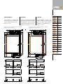
TYPE B27
The doors covering both top and
bottom panels and inset between
the side panels. The Distance be-
tween thelower edge of the door
and the bottom panel is 27 mm.
TYP B27
Aufschlagende Fronten am
Korpus und im lichten Abstand
zwischen den Seitenwänden.
Abstand "Front-Unterkante" -
"Basis" 27 mm.
TIPOLOGIA B27
Ante a ridosso su cielo e base
e in luce tra i fianchi laterali. Di-
stanza “bordo inferiore ante” -
“base” 27 mm.

14
COD. mm
LT
●
LA
●
HT
●
HI
●
HA
●
SPA
●
SPAM
●
SPB
●
SPC
●
SPE
●
SPI
●
SAE
AA
●
DYPL
●
DXPL
●
RAS
●
RM
●
REG
❏ EST.
❏ INC.
Slider M35 tipologia B27
regolatori esterni
Slider M35 tipologia B27
regolatori incassati
SPAM
max 40 mm
HA
HI
SPC
SPB
54
HT
SPA
SPAM
max 45 mm
HA
HI
SPC
SPB
54
HT
SPE SPESPI
LT
RM RM
LA LA
4
266
223.5
3150 150 3
27 27
212.5*
255*
DXPL
DYPL
DXPL
DYPL
Min 150 mm
Piedino laterale
Lateral foot
Seitlicher Stellfuß
Piedino laterale
Lateral foot
Seitlicher Stellfuß
Piedino centrale
Central foot
Zentraler Stellfuß
SPA
22.5
Min
60 mm
Min
60 mm
22.5
5454
RAS RAS
4 4
AA
SPE SPESPI
LT
RM RM
LA LA
4
DXPL
DYPL
DXPL
DYPL
Min 150 mm
Piedino laterale
Lateral foot
Seitlicher Stellfuß
Piedino laterale
Lateral foot
Seitlicher Stellfuß
Piedino centrale
Central foot
Zentraler Stellfuß
4 4
AA
RAS RAS
55 55
24 24
Min
60 mm
Min
60 mm
Slider M35 tipologia B43
regolatori esterni
Slider M35 tipologia B43
regolatori incassati
SPAM
max 40 mm
HA
HI
SPC
SPB
54
HT
SPA
SPAM
max 45 mm
HA
HI
SPC
SPB
54
HT
SPE SPESPI
LT
RM RM
LA LA
4
266
223.5 212.5*
255*
DXPL
DYPL
DXPL
DYPL
Min 150 mm
Piedino laterale
Lateral foot
Seitlicher Stellfuß
Piedino laterale
Lateral foot
Seitlicher Stellfuß
Piedino centrale
Central foot
Zentraler Stellfuß
SPA
Min
60 mm
Min
60 mm
5454
RAS RAS
4 4
AA
SPE SPESPI
LT
RM RM
LA LA
4
DXPL
DYPL
DXPL
DYPL
Min 150 mm
Piedino laterale
Lateral foot
Seitlicher Stellfuß
Piedino laterale
Lateral foot
Seitlicher Stellfuß
Piedino centrale
Central foot
Zentraler Stellfuß
4 4
AA
RAS RAS
150 3
43
12.5
150 3
43
12.5
5555
24 24
Min
60 mm
Min
60 mm
Slider M35 tipologia B27
regolatori esterni
Slider M35 tipologia B27
regolatori incassati
SPAM
max 40 mm
HA
HI
SPC
SPB
54
HT
SPA
SPAM
max 45 mm
HA
HI
SPC
SPB
54
HT
SPE SPESPI
LT
RM RM
LA LA
4
266
223.5
3150 150 3
27 27
212.5*
255*
DXPL
DYPL
DXPL
DYPL
Min 150 mm
Piedino laterale
Lateral foot
Seitlicher Stellfuß
Piedino laterale
Lateral foot
Seitlicher Stellfuß
Piedino centrale
Central foot
Zentraler Stellfuß
SPA
22.5
Min
60 mm
Min
60 mm
22.5
5454
RAS RAS
4 4
AA
SPE SPESPI
LT
RM RM
LA LA
4
DXPL
DYPL
DXPL
DYPL
Min 150 mm
Piedino laterale
Lateral foot
Seitlicher Stellfuß
Piedino laterale
Lateral foot
Seitlicher Stellfuß
Piedino centrale
Central foot
Zentraler Stellfuß
4 4
AA
RAS RAS
55 55
24 24
Min
60 mm
Min
60 mm
Slider M35 tipologia B43
regolatori esterni
Slider M35 tipologia B43
regolatori incassati
SPAM
max 40 mm
HA
HI
SPC
SPB
54
HT
SPA
SPAM
max 45 mm
HA
HI
SPC
SPB
54
HT
SPE SPESPI
LT
RM RM
LA LA
4
266
223.5 212.5*
255*
DXPL
DYPL
DXPL
DYPL
Min 150 mm
Piedino laterale
Lateral foot
Seitlicher Stellfuß
Piedino laterale
Lateral foot
Seitlicher Stellfuß
Piedino centrale
Central foot
Zentraler Stellfuß
SPA
Min
60 mm
Min
60 mm
5454
RAS RAS
4 4
AA
SPE SPESPI
LT
RM RM
LA LA
4
DXPL
DYPL
DXPL
DYPL
Min 150 mm
Piedino laterale
Lateral foot
Seitlicher Stellfuß
Piedino laterale
Lateral foot
Seitlicher Stellfuß
Piedino centrale
Central foot
Zentraler Stellfuß
4 4
AA
RAS RAS
150 3
43
12.5
150 3
43
12.5
5555
24 24
Min
60 mm
Min
60 mm
Regolatori incassati - Mounted adjustment elements
Eingebaute Ausrichtbeschläge
Regolatori esterni - External adjustment elements
Externe Ausrichtbeschläge
*Con telaio Clipper + 6 mm
*With Clipper frame + 6 mm
*Mit Clipper Beschlager + 6 mm
TIPOLOGIA B43
Ante a ridosso su cielo e base
e in luce tra i fianchi laterali. Di-
stanza “bordo inferiore ante” -
“base” 43 mm.
TYPE B43
The doors covering both top and
bottom panels and inset between
the side panels. The distance be-
tween the lower edge of the door
and the bottom panel is 43 mm.
TYP B43
Aufschlagende Fronten am
Korpus und im lichten Abstand
zwischen den Seitenwänden.
Abstand "Front-Unterkante" -
"Basis" 43 mm.
Tipologie Types Typen

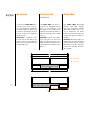
COME ORDINARE
- Meccanismi
su misura
HOW TO ORDER
- Customised
mechanisms
BESTELLUNG
- Nach Kunden-
spezifikationen
realisierte Beschläge

16
SPE SPE
LT
AA
LI
LP
LI = LT-2*SPE
LP= LI-1 mm
LI = LT-2*SPE
LP = LI-1 mm
Su misura Customised
systems
Nach Maß
I meccanismi Slider M35 pos-
sono essere richiesti “su misu-
ra”, cioé progettati (grazie alle
variabiali di pag. 10) per essere
installati su contenitori con luce
interna (LI) pari alla lunghezza
dei binari (LP).
Attenzione: l'apertura del-
le ante può essere decisa dal
cliente grazie alla variabile AA
(distanza tra la spalla centrale e
il bordo dell'anta).
The Slider M35 can be cus-
tomised, i.e., designed (on the
basis of the variables listed
on page 10) for installation on
cabinets with internal width (LI)
equal to the length of the slider
rail (LP).
Attention: clients can deter-
mine the extent to which the
door will open based on vari-
able AA (distance between the
central panel and edge of the
door).
Die Slider M35 Beschläge
können "nach Maß“ angefor-
dert bzw. entworfen werden
(dank der Variablen auf S. 10),
um an Korpussen mit einem
lichten Innenmaß (LI) gleich der
Schienenlänge (LP) installiert zu
werden.
Achtung: die Öffnung der Tür-
flügel kann dank der Variablen
AA (Abstand zwischen Korpus
Mittelseite und der seitlichen
Kante) vom Kunden entschie-
den werden.

MONTAGGIO
E REGOLAZIONI
ASSEMBLY AND
ADJUSTMENTS
MONTAGE UND
REGULIERUNG

18
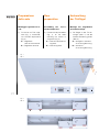
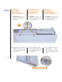
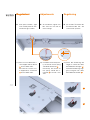
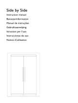
Fasi preparatorie
1) Prima di assemblare la strut-
tura, fissare le clip sulla parte
superiore del cielo (Fig. 1) e
sulla parte inferiore della base
(Fig. 2) con viti TPS.
1) Before mounting the mecha-
nism, fix the clips to the up-
per surface of the top panel
(Fig.1) and the underside of
the bottom panel (Fig. 2) us-
ing TPS screws.
1) Vor dem Zusammenbau des
Korpus, die Clips oben an
den Oberseiten (Abb. 1) und
unten am Sockel (Abb. 2) mit
Schrauben TPS befestigen.
Fig. 1
Abb. 1
Fig. 2
Abb. 2
Vorbereitungsphasen
Preparation

19
35
3) Apply the upper mechanism
to the top panel (Fig.3) mak-
ing certain that it fastens
correctly to the clips (Fig 4A
and 4B).
3) Den oberen Mechanismus
am Oberteil anbringen (Abb.
3), wobei darauf zu achten
ist, dass er korrekt an den
Clips eingehängt wird (Abb.
4A und 4B)
2) Mettere in bolla la struttura.
3) Applicare il meccanismo su-
periore sul cielo (Fig. 3) fa-
cendo attenzione che si ag-
ganci correttamente alle clip
(Fig. 4A e 4B).
Fig. 3
Abb. 3
Fig. 4A
Abb. 4A
Fig. 4B
Abb. 4B
Oberer
Gleitmechanismus
Upper sliding
mechanism
1) Ensure the cabinet is plumb
and level.
2) Den Korpus ins Lot bringen
bzw. waagrecht ausrichten.
Meccanismo
di scorrimento
superiore

20
Meccanismo
di scorrimento
superiore
4) Fissare il meccanismo con le
viti presenti alle due estremi-
tà.
4) Fasten the mechanism us-
ing the screws located at the
two ends.
4) Den Mechanismus mit den
Schrauben an den beiden
Enden befestigen.
Oberer
Gleitmechanismus
Upper sliding
mechanism
La pagina si sta caricando...
La pagina si sta caricando...
La pagina si sta caricando...
La pagina si sta caricando...
La pagina si sta caricando...
La pagina si sta caricando...
La pagina si sta caricando...
La pagina si sta caricando...
La pagina si sta caricando...
La pagina si sta caricando...
La pagina si sta caricando...
-
 1
1
-
 2
2
-
 3
3
-
 4
4
-
 5
5
-
 6
6
-
 7
7
-
 8
8
-
 9
9
-
 10
10
-
 11
11
-
 12
12
-
 13
13
-
 14
14
-
 15
15
-
 16
16
-
 17
17
-
 18
18
-
 19
19
-
 20
20
-
 21
21
-
 22
22
-
 23
23
-
 24
24
-
 25
25
-
 26
26
-
 27
27
-
 28
28
-
 29
29
-
 30
30
-
 31
31


Bortoluzzi slider M50 Manuale utente
- Tipo
- Manuale utente
- Questo manuale è adatto anche per
in altre lingue
- English: Bortoluzzi slider M50 User manual
- Deutsch: Bortoluzzi slider M50 Benutzerhandbuch
Altri documenti
-
 Slider SLIDER SMALL Guida Rapida
-
CAME 801XG-0048, 801XG-0049, 801XG-0050, 801XG-0051 Guida d'installazione
-
 De Dietrich DKK200X Manuale utente
-
Aeg-Electrolux SBSKITA2 Manuale utente
-
Caso WineMaster Touch 66 Istruzioni per l'uso
-
Caso WineComfort Touch 66 Istruzioni per l'uso
-
DeLonghi H 190510MEX1 Manuale del proprietario
-
Groupe Brandt NC-1500 Manuale del proprietario
-
Caso Wine Duett 12 Istruzioni per l'uso
-
Caso WineDuett 12 Istruzioni per l'uso

