La pagina si sta caricando...

ART./ITEM:
1486DTP20
1497DTP100
1578DTP100/23
La dichiarazione CE del presente articolo è
reperibile sul sito www.lince.net.
L’installazione dei prodotti riportati nel presente
manuale deve essere eseguita da personale
specializzato in possesso delle dovute conoscenze
tecniche; i prodotti sono stati progettati per utilizzo in
contesti domestici e civili.
The CE declaration of this item is available on
www.lince.net website.
The installation of the products listed in this manual
must be performed by specialized personnel with the
necessary technical knowledge; the products have
been designed for use in domestic and civil contexts.
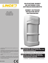
IT RIVELATORE DI PRESENZA A DOPPIA
TECNOLOGIA
Manuale di installazione, programmazione ed uso.
- Istruzioni originali -
DESCRIZIONE
I rilevatori serie DTP riuniscono in un unico dispositivo un
sensibile rilevatore a microonda ed un sensore ad infrarosso.
Appositamente studiati e realizzati per il funzionamento in
ambienti molto difcili garantiscono un eccellente grado di
immunità a fenomeni che in altri tipi di sensori possono causare
falsi allarmi.
La sequenza dei preallarmi forniti dai due sensori presenti
viene opportunamente analizzata dal microprocessore evitando
così che fenomeni esterni come correnti d’aria, sorgenti di
calore, e disturbi di origine elettrica diano luogo ad indesiderati
allarmi. Facilmente adattabile a qualsiasi tipo di installazione
sia a parete che ad angolo è dotato di LED per la verica del
corretto orientamento e regolazioni di sensibilità dei sensori. La
programmazione delle funzioni del rilevatore si effettua tramite
dip-switch (solo per 1497DTP100 e 1578DTP100/23)
EN DOUBLE TECHNOLOGY DETECTOR
Installation, programming and operating manual.
- Translation of original instructions -
DESCRIPTION
The DTP series detectors combines in only one device a
microwave detector with an infrared sensor. On purpose studied
and realized to guarantee perfect functioning in difcult places,
it also guarantees high immunity against phenomena which in
other different devices may cause false alarms.
The sequence of the pre-alarms provided by the two built-in
sensors, is duly analysed by the microprocessor, thus avoiding
that external phenomena such as air currents, heat sources,
little animal movements or electric origin troubles, may cause
undesired false alarms.
Suitable both on wall and corner installations, it is supplied
with luminous indicators to check correct orientation and
adjustment of sensor sensitivity. Programmation of the detector’s
functions is made by the dip switch (only for 1497DTP100 and
1578DTP100/23).
CARATTERISTICHE TECNICHE
1486DTP20 1497DTP100 1578DTP100/23
Sensore infrarosso / Infrared sensor Doppio elemento a basso rumore / Double low noise element
Frequenza microonda / Microwave frequency 10,525 GHz strip line
Portata / Range 15 m 20 m 23 m
Copertura orizzontale / Horizontal coverage 90°
Alimentazione / Power supply 8 ÷16 Vcc
Assorbimento Stand-By / Stand-by Consumption 38 mA
Relè di allarme / Alarm relay N.C. 10 Ω in serie / N.C. 10 Ω in series
Installazione / Installation A parete / Wall mountable
Switch antisabotaggio / Anti-tamper switch N.C. contatto dedicato / N.C. dedicated contact
Temperatura di esercizio / Operating temperature 5° ÷ +40°C
Dimensioni (mm LxHxP) / Dimensions (WxHxD mm) 71 x 102 x 56 senza snodo / without bracket
Peso / Weight 106 g
TECHNICAL FEATURES
MADE IN ITALY
RIVELATORE DI PRESENZA A DOPPIA TECNOLOGIA
DOUBLE TECHNOLOGY DETECTOR

LINCE ITALIA
2
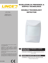
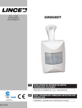
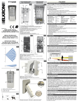
1497DTP100 1578DTP100/23 1486DTP20
MW TRIMMER
IR TRIMMER
DIP SWITCH
Fig. 1
AA
CC
BB
LED
JUMPER
AND/OR
JUMPER
INSTALLAZIONE
Individuare il punto dove ssare il sensore valutando i passaggi
più probabili e gli oggetti più facilmente asportabili da un
eventuale intruso. L’altezza consigliata è di 2,2 m. Per il ssaggio
agire come segue: Togliere la copertura facendo pressione sugli
incastri ( C ). Fissare il supporto di ssaggio (A) con la vite ed il
tassello in dotazione ad un’altezza da terra compresa tra i 2,10
mt e i 2,30 m. Fissare il sensore al supporto e prima di serrare
le viti ( B ) orientare il sensore secondo le esigenze. Effettuare i
collegamenti, chiudere il sensore facendo attenzione che gli scatti
automatici siano incastrati. Se necessario è possibile eliminare lo
snodo di ssaggio ( A ) e ssare direttamente il sensore a parete,
o ad angolo usando le preforature previste.
COLLEGAMENTI
I collegamenti al rilevatore devono essere effettuati con cavo
schermato: collegare lo schermo alla massa della centrale
lasciandolo scollegato dalla parte del sensore. Se la distanza tra
il rilevatore e la centrale è notevole, assicurarsi che non vi sia
caduta di tensione.
INSTALLATION
Find a place where to x the sensor, evaluating the most probable
passages and the objects which could be easily removed by
possible intruders. Advisable height is 2.2 m. For the xing act
as follows (see C) Take the cover off by making pressure on the
joints (A) Fix the xing support (g. 2) with the screw and the
supplied dowel at a height between 2,10 and 2,30 m. Fix the
sensor to the support and before tightening the screw, direct
the sensor. Make the connections and close the sensor paying
attention that the automatic clicks are well stuck. If necessary it is
possible to eliminate the xing articulation (A) and directly x the
sensor to the wall by using the pre- perforations.
CONNECTIONS
Connections with detectors must be performed with shielded
cable: Connect the shield to the control panel earth, leaving
it unconnected on the detector side. If the distance between
detector and control panel is signicant, ensure there is no
voltage drop.
Morsetto /
Terminal block Descrizione Description
WT Morsetto per l'esclusione a distanza dei LED di allarme, e abilitazione memoria
(vedi paragrafo Esclusione LED ed abilitazione memoria).
Terminal for remote exclusion of the alarm LEDs and memory enabling (see para.
“LEDs exclusion and memory enabling)
AS Contatti dello switch antisabotaggio (8) Normalmente chiuso: Collegare questi
morsetti alla linea antisabotaggio Tamper switch contacts (8) NC: Connect these terminals to the tamper line
NC Contatti del relé di allarme Normalmente Chiuso: Collegare ad una linea di allarme NC alarm relay contact: connect to an alarm line
AC
Contatto relè N.C. dell’antimascheramento. Si apre quando il sensore attiva
l’allarme Antimask e Warning.
Solo per 1497DTP100 e 1578DTP100/23
NC relay contact: Antimask. It opens when the sensor activates the Antimask and
Warning alarm.
Only for 1497DTP100 and 1578DTP100/23
+/- Morsetti di alimentazione 12V , 34mA, quando il sensore viene alimentato impiega
circa 60 sec. Per stabilizzarsi.
Power terminal: 12V 34mA. Once the sensor is powered it takes 60 sec. to become
stable.

3
LINCE ITALIA.
ESCLUSIONE LED DI ALLARME 1486DTP20
Il morsetto WT consente di escludere a distanza i tre LED , ed il
relé di allarme. Se si vuole che i LED di allarme (LED verde, giallo
e rosso) non segnalino i movimenti rilevati a centrale disinserita,
si deve inviare un positivo sul questo morsetto quando l’impianto
è disinserito (+OFF sulle centrali Lince). E’ possibile escludere in
modo permanente i LED, slando il jumper LED OFF presente
sulla scheda. (vedi g 1)
ALARM EXCLUSION 1486DTP20
The WT terminal allows to remotely exclude the three alarm
LEDs and the alarm relays. If you want the alarm LEDs (green,
yellow and red) to do not signal the detected movements when
the control panel is off, You must send a positive on this terminal
(+OFF on LINCE control panels). It is possible to permanently
exclude the LEDs by removing the LED OFF jumper on the board
(see g 1)
MASCHERAMENTO 1497DTP100 /1578DTP100/23
Ad impianto inserito, il rilevatore è operativo anche in caso di
accecamento del sensore infrarosso dopo 5 rilevazioni (entro 30
secondi ) della microonda.
MASKING 1497DTP100 /1578DTP100/2
When the system is on, in case the infrared sensor has been
covered, the alarm will be switched on after 5 pre-alarms (Within
3 s) of the microwave.
WARNING 1497DTP100 /1578DTP100/2
Quando i LED sono inibiti, (positivo sul morsetto WT), in
caso di guasto o accecamento di una delle due tecnologie,
il microprocessore, esclude automaticamente il sensore che
non risponde. L’anomalia verrà segnalata con l’apertura dello
scambio AC ed il lampeggio del LED corrispondente alla
tecnologia guasta, il ripristino avverrà alla prima rilevazione utile
della tecnologia accecata.
NOTA:
Se si toglie il positivo da WT il sensore ripristina la visualizzazione
dei LED dopo circa 15/20 secondi
WARNING 1497DTP100 /1578DTP100/2
When the LEDs are inhibited (+OFF on the WT terminal) in
case of fault or masking of one of the two technologies, the
microprocessor automatically excludes the sensor that does
not answer, thus signalling the anomaly by the ashing up of
the corresponding LED. The AC exchange will be opened thus
signalling the anomaly and the LED of the correspondent to the
faulty technology will ash up.
NOTE:
If positive is taken away form the WT, the sensor restores the
LED visualisation after about 15/20 seconds.
FUNZIONE DEI LED
LED giallo: Lampeggiante, la microonda sta rilevando del
movimento nell’ambiente.
LED verde: Acceso sso, il sensore infrarosso ha rilevato una
presenza.
LED rosso: Acceso sso, condizione di allarme.
LED MEANING
Yellow: Flashing, it indicates that the microwave is detecting a
movement.
Green: On x, it indicates that the infrared sensor has been
detecting.
Red: On x, alarm condition.
PROGRAMMAZIONE 1497DTP100/1578DTP100/23
Tramite i dip-switch è possibile programmare il rilevatore a
seconda delle proprie necessità.
SETTINGS 1497DTP100/1578DTP100/23
Through the dip-switches it is possible to program the detector
according to your needs.
Dipswitch Funzione On Off
1LED ACCESI/ON SPENTI/OFF
2AND/OR OR AND
3ANTIMASK ACCESO/ON SPENTO/OFF
4WARNING ACCESO/ON SPENTO/OFF
PROGRAMMAZIONE 1486DTP20
Tramite il ponticello slabile (jumper) è possibile programmare il
sensore per due distinti modi di funzionamento:
JUMPER INSERITO = AND: Il DTP20 invia l’allarme solo se
entrambi i sensori rilevano contemporaneamente un’intrusione.
JUMPER SFILATO = OR: Il DTP20 invia l’allarme anche se a
rilevare è uno solo dei due sensori.
SETTINGS 1486DTP20
By the exctractable jumper it is possible to programme the sensor
in two different ways:
JUMPER ON = AND: The DTP20 sends the alarm only if both
sensorcontemporaneouslydetectanintrusion.
JUMPER OFF = OR: The DPT20 sends the alarm even if only
one sensor is detecting.
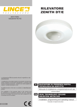
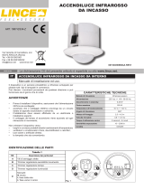
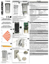
COPERTURA 1486DTP20
La copertura dell’area protetta è determinata dall’effetto
combinato dei due sensori presenti all’interno del DTP20. La
microonda ha un angolo di copertura di 90° sul piano orizzontale
mentre il sensore infrarosso, all’interno della stessa area,
dispone di 24 fasci su 4 livelli, ognuno dei quali genera un
segnale differenziale. Nella gura sono riportati sia i fasci del
sensore infrarosso sia, mediante linea continua, l’area coperta
dalla microonda.
COVERAGE AREA 1486DTP20
The protected area is determined by the combined effect of the
two sensors inside the DTP 20.
The microwave has a 90° covering angle on horizontal plane,
while the infrared sensor in the same area has 24 beams on 4
levels, each of them generates a differential sensor. In the gure
here below, we show both the infrared beams and the microwave
area (continuous line)

001530/00801AD REV0
LINCE ITALIA S.r.l.
Via Variante di Cancelliera, snc
00072 ARICCIA (Roma)
Tel. +39 06 9301801
Fax +39 06 930180232
info@lince.net
www.lince.net
20 m6 m3 m1 m
2,1 m
0
5 m
10 mt
5 m
10 m
1497DTP100
Fig. 2 1578DTP100/23 1486DTP20
TEST DI COPERTURA 1486DTP20
Eseguire una prova di portata del DTP aumentando gradualmente
la sensibilità della microonda tramite il trimmer (range) al ne di
ottenere l’accensione del LED giallo no al limite della zona da
proteggere e non oltre.
NOTA: La prova di copertura và effettuata con il sensore perfe
chiuso
COVERAGE TEST 1486DTP20
Where the DTP is instalLED, test the covering by gradually
increase the microwave’s sensitivity range (trimmer) so that the
yellow LED lights up til the zone to protect and not over.
NOTE.: Covering test shall be effected with a perfectly closed
detector
COPERTURA 1497DTP100/1578DTP100/23
La copertura dell’area protetta è determinata dall’effetto
combinato dei due sensori presenti all’interno del DTP20. La
microonda ha un angolo di copertura di 90° sul piano orizzontale
mentre il sensore infrarosso, all’interno della stessa area,
dispone di 24 fasci su 4 livelli, ognuno dei quali genera un
segnale differenziale. Nella gura sono riportati sia i fasci del
sensore infrarosso sia, mediante linea continua, l’area coperta
dalla microonda.
COVERAGE AREA 1497DTP100/1578DTP100/23
The protected area is determined by the combined effect of the
two sensors inside the DTP 20.
The microwave has a 90° covering angle on horizontal plane,
while the infrared sensor in the same area has 24 beams on 4
levels, each of them generates a differential sensor. In the gure
here below, we show both the infrared beams and the microwave
area (continuous line)
TEST COPERTURA 1497DTP100/1578DTP100/23
Eseguire una prova di portata del DTP aumentando gradualmente
la sensibilità della microonda tramite il trimmer (range) al ne di
ottenere l’accensione del LED giallo no al limite della zona da
proteggere e non oltre.
NOTA: La prova di copertura và effettuata con il sensore perfe
chiuso
COVERAGE TEST 1497DTP100/1578DTP100/23
Where the DTP is instalLED, test the covering by gradually
increase the microwave’s sensitivity range (trimmer) so that the
yellow LED lights up til the zone to protect and not over.
NOTE.: Covering test shall be effected with a perfectly closed
detector
SMALTIMENTO E ROTTAMAZIONE
Smaltire il materiale di imballo secondo i codici identicativi
riportati sul materiale stesso:
• PAP 20 / PAP 21 – raccolta differenziata carta;
• PVC 3 / LDPE 4 / O 7 – raccolta differenziata plastica.
Vericare il sistema di raccolta del proprio comune.
• Svitare il fondo, rimuovere la pila e tutte le parti del prodotto
quali scheda e contenitore plastico;
• Dividere le parti in base alla loro tipologia e smaltirle in
accordo con le leggi vigenti.
ATTENZIONE!
Non disperdere nell’ambiente i componenti ed ogni
altro materiale del prodotto. Rivolgersi a consorzi
abilitati allo smaltimento ed al riciclaggio dei materiali.
DISPOSAL AND SCRAPPING
Dispose of the packaging material according to the identication
codes shown on the material itself:
• PAP 20 / PAP 21 - separate paper collection;
• PVC 3 / LDPE 4 / O 7 - plastic separate collection.
Check your municipality's collection system.
• Unscrew the bottom, remove the battery and all parts of the
product such as the board and plastic case;
• Divide the parts by type and dispose of them in accordance
with applicable laws.
IMPORTANT!
Do not dispose of the components or any other pro-
duct material in the environment. Seek the assistan-
ce of companies authorised to dispose of and recycle waste
materials.
1/4