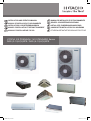
Hitachi RAS-10HNCE Istruzioni per l'uso
- Categoria
- Condizionatori d'aria a sistema split
- Tipo
- Istruzioni per l'uso

INSTALLATION AND OPERATION MANUAL
MANUAL DE INSTALACIÓN Y FUNCIONAMIENTO
INSTALLATIONS- UND BETRIEBSHANDBUCH
MANUEL D’INSTALLATION ET DE FUNCTIONNEMENT
MANUALE D’INSTALLAZIONE E D’USO
MANUAL DE INSTALAÇÃO E DE FUNCIONAMENTO
BRUGER- OG MONTERINGSVEJLEDNING
INSTALLATIE- EN BEDIENINGSHANDLEIDING
HANDBOK FÖR INSTALLATION OCH ANVÄNDING
ΕΓΧΕΙΡΙΔΙΟΕΓΚΑΤΑΣΤΑΣΗΣΚΑΙΛΕΙΤΟΥΡΓΙΑΣ
UTOPIA IVX PREMIUM / IVX STANDARD Series
RAS-(3-10)H(V)NPE / RAS-(4-10)H(V)NCE
PMML0251A rev.2 - 02/2013 Printed in Spain
PMML0251A rev.2 - 02/2013
UTOPIA IVX PREMIUM / IVX STANDARD SERIES
_PMML0251A_r2.indb 1 06/02/2013 9:04:41

_PMML0251A_r2.indb 2 06/02/2013 9:04:41

Specications in this manual are subject to change without notice in order that HITACHI may bring the latest innovations to their
customers.
Whilst every effort is made to ensure that all specications are correct, printing errors are beyond Hitachi’s control; Hitachi can-
not be held responsible for these errors.
Las especicaciones de este manual están sujetas a cambios sin previo aviso a n de que HITACHI pueda ofrecer las últimas
innovaciones a sus clientes.
A pesar de que se hacen todos los esfuerzos posibles para asegurarse de que las especicaciones sean correctas, los errores
de impresión están fuera del control de HITACHI, a quien no se hará responsable de ellos.
Bei den technischen Angaben in diesem Handbuch sind Änderungen vorbehalten, damit HITACHI seinen Kunden die jeweils
neuesten Innovationen präsentieren kann.
Sämtliche Anstrengungen wurden unternommen, um sicherzustellen, dass alle technischen Informationen ohne Fehler
veröffentlicht worden sind. Für Druckfehler kann HITACHI jedoch keine Verantwortung übernehmen, da sie außerhalb ihrer
Kontrolle liegen.
Les caractéristiques publiées dans ce manuel peuvent être modiées sans préavis, HITACHI souhaitant pouvoir toujours offrir à
ses clients les dernières innovations.
Bien que tous les efforts sont faits pour assurer l’exactitude des caractéristiques, les erreurs d’impression sont hors du contrôle
de HITACHI qui ne pourrait en être tenu responsable.
Le speciche di questo manuale sono soggette a modica senza preavviso afnché HITACHI possa offrire ai propri clienti le
ultime novità.
Sebbene sia stata posta la massima cura nel garantire la correttezza dei dati, HITACHI non è responsabile per eventuali errori
di stampa che esulano dal proprio controllo.
As especicações apresentadas neste manual estão sujeitas a alterações sem aviso prévio, de modo a que a HITACHI possa
oferecer aos seus clientes, da forma mais expedita possível, as inovações mais recentes.
Apesar de serem feitos todos os esforços para assegurar que todas as especicações apresentadas são correctas, quaisquer
erros de impressão estão fora do controlo da HITACHI, que não pode ser responsabilizada por estes erros eventuais.
Specikationerne i denne vejledning kan ændres uden varsel, for at HITACHI kan bringe de nyeste innovationer ud til kunderne.
På trods af alle anstrengelser for at sikre at alle specikationerne er korrekte, har Hitachi ikke kontrol over trykfejl, og Hitachi
kan ikke holdes ansvarlig herfor.
De specicaties in deze handleiding kunnen worden gewijzigd zonder verdere kennisgeving zodat HITACHI zijn klanten kan
voorzien van de nieuwste innovaties.
Iedere poging wordt ondernomen om te zorgen dat alle specicaties juist zijn. Voorkomende drukfouten kunnen echter niet door
Hitachi worden gecontroleerd, waardoor Hitachi niet aansprakelijk kan worden gesteld voor deze fouten.
Specikationerna i den här handboken kan ändras utan föregående meddelande för att HITACHI ska kunna leverera de senaste
innovationerna till kunderna.
Vi på Hitachi gör allt vi kan för att se till att alla specikationer stämmer, men vi har ingen kontroll över tryckfel och kan därför
inte hållas ansvariga för den typen av fel.
Οι προδιαγραφές του εγχειριδίου μπορούν να αλλάξουν χωρίς προειδοποίηση, προκειμένου η HITACHI να παρέχει τις
τελευταίες καινοτομίες στους πελάτες της.
Αν και έχει γίνει κάθε προσπάθεια προκειμένου να εξασφαλιστεί ότι οι προδιαγραφές είναι σωστές, η Hitachi δεν μπορεί να
ελέγξει τα τυπογραφικά λάθη και, ως εκ τούτου, δεν φέρει καμία ευθύνη για αυτά τα λάθη.
_PMML0251A_r2.indb 3 06/02/2013 9:04:42

ATTENTION:
This product shall not be mixed with general house waste at the end of its life and it shall be retired according
to the appropriated local or national regulations in a environmentally correct way.
Due to the refrigerant, oil and other components contained in Air Conditioner, its dismantling must be done by
a professional installer according to the applicable regulations.
Contact to the corresponding authorities for more information.
ATENCIÓN:
Éste producto no se debe eliminar con la basura doméstica al nal de su vida útil y se debe desechar de ma-
nera respetuosa con el medio ambiente de acuerdo con los reglamentos locales o nacionales aplicables.
Debido al refrigerante, el aceite y otros componentes contenidos en el sistema de aire acondicionado, su des-
montaje debe realizarlo un instalador profesional de acuerdo con la normativa aplicable.
Para obtener más información, póngase en contacto con las autoridades competentes.
ACHTUNG:
Dass Ihr Produkt am Ende seiner Betriebsdauer nicht in den allgemeinen Hausmüll geworfen werden darf,
sondern entsprechend den geltenden örtlichen und nationalen Bestimmungen auf umweltfreundliche Weise
entsorgt werden muss.
Aufgrund des Kältemittels, des Öls und anderer in der Klimaanlage enthaltener Komponenten muss die De-
montage von einem Fachmann entsprechend den geltenden Vorschriften durchgeführt werden.
Für weitere Informationen setzen Sie sich bitte mit den entsprechenden Behörden in Verbindung.
ATTENTION:
Ne doit pas être mélangé aux ordures ménagères ordinaires à la n de sa vie utile et qu’il doit être éliminé
conformément à la réglementation locale ou nationale, dans le plus strict respect de l’environnement.
En raison du frigorigène, de l’huile et des autres composants que le climatiseur contient, son démontage doit
être réalisé par un installateur professionnel conformément aux réglementations en vigueur.
ATTENZIONE:
Indicazioni per il corretto smaltimento del prodotto ai sensi della Direttiva Europea 2002/96/EC e Dlgs 25 luglio
2005 n.151
Il simbolo del cassonetto barrato riportato sull’ apparecchiatura indica che il prodotto alla ne della propria vita
utile deve essere raccolto separatamente dagli altri riuti.
L’utente dovrà, pertanto, conferire l’apparecchiatura giunta a ne vita agli idonei centri di raccolta differenziata
dei riuti elettronici ed elettrotecnici, oppure riconsegnarla al rivenditore al momento dell’ acquisto di una nuo-
va apparecchiatura di tipo equivalente.
L’adeguata raccolta differenziata delle apparecchiature dismesse, per il loro avvio al riciclaggio, al trattamento
ed allo smaltimento ambientalmente compatibile, contribuisce ad evitare possibili effetti negativi sull’ ambiente
e sulla salute e favorisce il riciclo dei materiali di cui è composta l’ apparecchiatura.
Non tentate di smontare il sistema o l’unità da soli poichè ciò potrebbe causare effetti dannosi sulla vostra
salute o sull’ ambiente.
Vogliate contattare l’ installatore, il rivenditore, o le autorità locali per ulteriori informazioni.
Lo smaltimento abusivo del prodotto da parte dell’utente può comportare l’applicazione delle sanzioni ammi-
nistrative di cui all’articolo 50 e seguenti del D.Lgs. n. 22/1997.
ATENÇÃO:
O seu produto não deve ser misturado com os desperdícios domésticos de carácter geral no nal da sua du-
ração e que deve ser eliminado de acordo com os regulamentos locais ou nacionais adequados de uma forma
correcta para o meio ambiente.
Devido ao refrigerante, ao óleo e a outros componentes contidos no Ar condicionado, a desmontagem deve
ser realizada por um instalador prossional de acordo com os regulamentos aplicáveis.
Contacte as autoridades correspondentes para obter mais informações.
BEMÆRK:
At produktet ikke må smides ud sammen med almindeligt husholdningsaffald, men skal bortskaffes i overenss-
temmelse med de gældende lokale eller nationale regler på en miljømæssig korrekt måde.
Da klimaanlægget indeholder kølemiddel, olie samt andre komponenter, skal afmontering foretages af en fag-
mand i overensstemmelse med de gældende bestemmelser.
Kontakt de pågældende myndigheder for at få yderligere oplysninger.
ATTENTIE:
Dit houdt in dat uw product niet wordt gemengd met gewoon huisvuil wanneer u het weg doet en dat het wordt
gescheiden op een milieuvriendelijke manier volgens de geldige plaatselijke en landelijke reguleringen.
Vanwege het koelmiddel, de olie en andere onderdelen in de airconditioner moet het apparaat volgens de
geldige regulering door een professionele installateur uit elkaar gehaald worden.
Neem contact op met de betreffende overheidsdienst voor meer informatie.
OBS!:
Det innebär att produkten inte ska slängas tillsammans med vanligt hushållsavfall utan kasseras på ett
miljövänligt sätt i enlighet med gällande lokal eller nationell lagstiftning.
Luftkonditioneringsaggregatet innehåller kylmedium, olja och andra komponenter, vilket gör att det måste de-
monteras av en fackman i enlighet med tillämpliga regelverk.
Ta kontakt med ansvarig myndighet om du vill ha mer information.
ΠΡΟΣΟΧΗ:
Σημαίνει ότι το προϊόν δεν θα πρέπει να αναμιχθεί με τα διάφορα οικιακά απορρίμματα στο τέλος του κύκλου
ζωής του και θα πρέπει να αποσυρθεί σύμφωνα με τους κατάλληλους τοπικούς ή εθνικούς κανονισμούς και με
τρόπο φιλικό προς το περιβάλλον.
Λόγω του ψυκτικού, του λαδιού και άλλων στοιχείων που περιέχονται στο κλιματιστικό, η αποσυναρμολόγησή
του πρέπει να γίνει από επαγγελματία τεχνικό και σύμφωνα με τους ισχύοντες κανονισμούς.
Για περισσότερες λεπτομέρειες, επικοινωνήστε με τις αντίστοιχες αρχές.
_PMML0251A_r2.indb 4 06/02/2013 9:04:42

English
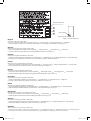
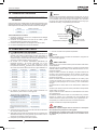
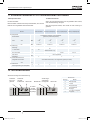
From 4th July 2007 and following Regulation EC Nº 842/2006 on Certain Fluorinated Greenhouse gases, it is mandatory to ll in the label attached to the unit
with the total amount of refrigerant charged on the installation.
Do not vent R410A/R407C into the atmosphere: R410A & R407C are uorinated greenhouse gases covered by the Kyoto protocol global warming potential
(GWP) R410A/R407C: = 1975/1652.5.
Español
Desde el 4 de Julio de 2007 y en base al Reglamento CE Nº 842/2006 sobre determinados gases uorados de efecto invernadero, es obligatorio rellenar la
etiqueta suministrada con la unidad con la cantidad total de refrigerante con que se ha cargado la instalación.
No descargue el R410A/R407C en la atmósfera: R410A y R407C son gases uorados cubiertos por el protocolo de Kyoto con un potencial de calentamiento
global (GWP): = 1975/1652.5.
Deutsch
Ab 4. Juli 2007 und folgende Verordnung EG Nr. 842/2006 Bestimmte uorierte Treibhausgase, auf dem Schild, das sich am Gerät bendet, muss die
Gesamtkältemittelmenge verzeichnet sein, die bei der Installation eingefüll wird.
Lassen sie R410A/R407C nicht in die luft entweichen: R410A & R407C sind uorierte treibhausgase, die durch das Kyoto-protokoll erfasst sind. Sie besitzen
folgendes treibhauspotential (GWP) R410A/R407C: = 1975/1652.5.
France:
Du 4 Juillet 2007 et en fonction de la Réglementation CE Nº 842/2006 concernant certains gaz à effet de serre uorés, il est obligatoire de remplir l'étiquette
attachée à l'unité en indiquant la quantité de uide frigorigène qui a été chargée à l'installation.
Ne laissez pas le R410A/R407C se répandre dans l'atmosphère: le R410A et le R407C sont des gaz à effet de serre uorés, couverts par le protocole de
Kyoto avec un potentiel de rechauffement global (PRG) R410A/R407C: = 1975/1652.5.
Italiano
Dal 4 Luglio 2007 e in base alla Normativa EC Nº 842/2006 su determinati gas uorurati ad effetto serra, è obbligatorio compilare l'etichetta che si trova
sull'unità inserendo la quantità totale di refrigerante caricato nell'installazione.
Non scaricare R410A/R407C nell'atmosfera: R410A e R407C sono gas uorurati ad effetto serra che in base al protocollo di Kyoto presentano un potenziale
riscaldamento globale (GWP) R410A/R407C: = 1975/1652.5.
Português
A partir de 4 de Julho de 2007 e em conformidade com a Regulamentação da UE Nº 842/2006 sobre determinados gases uorados com efeito de estufa, é
obrigatório preencher a etiqueta axada na unidade com a quantidade total de refrigerante carregada na instalação.
Não ventilar R410A/R407C para a atmosfera: o R410A e o R407C são gases uorados com efeito de estufa abrangidos pelo potencial de aquecimiento global
(GWP) do protocolo de Quioto: = 1975/1652.5.
Dansk
Fra d. 4. Juli 2007 og i henhold til Rådets forordning (EF) nr. 842/2006 om visse uorholdige drivhusgasser, skal installationens samlede mængde kølevæske
fremgå at den etiket, der er klæbet fast på enheden.
Slip ikke R410A/R407C ud i atmosfæren: R410 & R407C er uorholdige drivhus-gasser, der er omfattet af Kyoto-protokollens globale opvarmningspotentiale
(GWP) R410A/R407C: = 1975/1652.5.
Nederlands
Vanaf 4 Juli 2007 en conform richtlijn EC Nº 842/2006 voor bepaalde uorbroeikasgassen, dient u de tabel in te vullen op de unit met het totale koelmiddel-
volume in de installatie.
Laat geen R410A/R407C ontsnappen in de atmosfeer: R410A & R407C zijn uorbroeikasgassen die vallen onder het protocol van Kyoto inzake klimaatve-
randering global warming potential (GWP) R410A/R407C: = 1975/1652.5.
Svenska
Från och med 4 Juli 2007 och enligt reglering EC Nº 842/2006 om vissa uorhaltiga växthusgaser, måste etiketten som sitter på enheten fyllas i med sam-
manlagd mängd kylmedium som fyllts på under installationen.
Släpp inte ur R410A/R407C i atmosfären: R410A & R407C är uorhaltiga växthus-gaser som omfattas av Kyotoprotokollet om global uppvärmnings-potential
(GWP) R410/R407C: = 1975/1652.5.
Eλλhnika
Από τις 4 Ιουλίου 2007 και σύμφωνα με τον Κανονισμό 842/2006/ΕΚ για για ορισμένα φθοριούχα αέρια θερμοκηπίου, είναι υποχρεωτική η συμπλήρωση της
επισήμανσης που επισυνάπτεται στη μονάδα με το συνολικό ποσό ψυκτικού που εισήχθη κατά την εγκατάσταση.
Μην απελευθερωνετε R410A/R407C στην ατμοσφαιρα τα R410A & R407C ειναι φθοριουχα αερια του θερμοκηπιου που εμπιπτουν στο πρωτοκολλο του
κυοτο δυναμικο θερμανσησ του πλανητη (GWP) R410A/R407C: = 1975/1652.5
_PMML0251A_r2.indb 5 06/02/2013 9:04:43

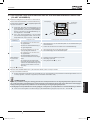
English
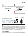
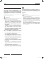
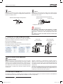
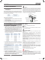
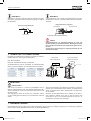
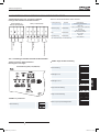
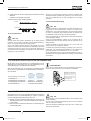
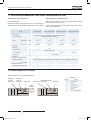
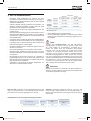
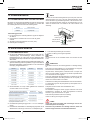
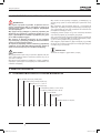
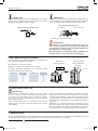
Instructions to ll in the "F-Gas Label":
1.- Fill in the Label with indelible ink the refrigerant amounts:
- Factory Charge,
- Additional Charge &
- Total Charge.
2.- Stick the Protection Plastic Film on the F-Gas Label (delivered in a plastic bag with the Manual). To see Figure nº 2.
Español
Instrucciones para rellenar la etiqueta "F-Gas Label":
1.- Anote las cantidades en la etiqueta con tinta indeleble:
- Carga de Fábrica,
- Carga Adicional y
- Carga Total.
2.- Coloque el adhesivo plástico de protección (entregado adjunto al Manual). Ver Figura nº 2.
Deutsch
Anleitung zum Ausfüllen des Etiketts "F-Gas Label":
1.- Schreiben Sie die Mengen mit wischfester Tinte auf das Etikett:
- Werksbefüllung,
- Zusätzliche Befüllung &
- Gesamtfüllmenge.
2.- Bringen Sie den Schutzaufkleb an (zusammen mit dem Handbuch geliefert). Siehe Abbildung Nr. 2.
France:
Instructions pour remplir l'Étiquette "F-Gas Label":
1.- Annotez les quantités sur l'Étiquette avec de l'encre indélébile:
- Charge en usine,
- Charge supplémentaire et
- Charge totale.
2.- Placez le plastique autocollant de protection (remis avec le Manual). Voir Figure nº 2.
Italiano
Istruzioni per compilare l'Etichetta "F-Gas Label":
1.- Annotare le quantità sull'etichetta con inchiostro indelebile:
- Quantità già caricata,
- Carica aggiuntiva e
- Carica totale.
2.- Collocare l'adesivo plastico di protezione (consegnato assieme al Manuale). Vedere Figura n. 2.
Português
Instruções para preencher a etiqueta "F-Gas Label":
1.- Anote as quantidades na etiqueta com tinta indelével:
- Carga de fábrica,
- Carga adicional e
- Carga total.
2.- Coloque o adesivo plástico de protecção (fornecido com o Manual). Ver Figura nº 2.
Dansk
Instruktioner til udfyldning af etiketten "F-Gas Label":
1.- Angiv mængderne på etiketten med uudsletteligt blæk:
- Fabrikspåfyldning,
- Ekstrapåfyldning &
- Samletpåfyldning.
2.- Sæt det beskyttende klæbemærke (der leveres sammen med brugervejledningen) på. Se g. 2.
Nederlands
Instructies voor het invullen van het label "F-Gas Label":
1.- Noteer de hoeveelheden met onuitwisbare inkt op het label:
- Fabrieksvulling,
- Extra vulling &
- Totale vulling.
2.- Plaats de plastic beschermband (met de handleiding meegeleverd). Zie Figuur nr. 2.
Svenska
Instruktioner för påfyllning, etiketten "F-Gas Label":
1.- Anteckna kvantiteterna på etiketten med permanent bläck:
- Fabrikspåfyllning,
- Ytterligare påfyllning &
- Total påfyllning.
2.- Klistra på skyddslmen i plast (nns i pärmen till handboken). Se bild nr. 2.
Eλλhnika
Τρόπος συμπλήρωσης της ετικέτας "F-Gas Label":
1.- Σημειώστε στην ετικέτα τις ποσότητες με ανεξίτηλο μελάνι:
- Εργοστασιακή πλήρωση,
- Πρόσθετη πλήρωση &
- Συνολική πλήρωση.
2.- Τοποθετήστε το πλαστικό, προστατευτικό αυτοκόλλητο (που έχει παραδοθεί με το Εγχειρίδιο). Ανατρέξτε στην εικόνα 2
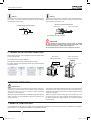
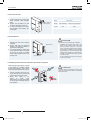
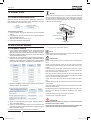
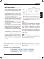
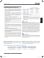
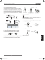
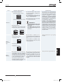
Figure 1. F-Gas Label with Protection Plastic Film Figure 2. Protection Plastic Film
Protection Plastic Film
Adhesive Surface
Peel-off Paper
_PMML0251A_r2.indb 6 06/02/2013 9:04:45

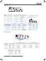
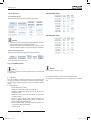
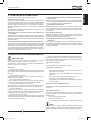
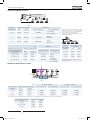
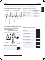
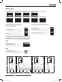
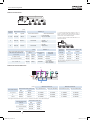
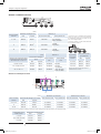
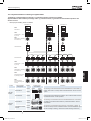
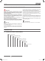
MODELS CODIFICATION
Important note: Please, check, according to the model name, which is your air conditioner type,
how it is abbreviated and referred to in this instruction manual. This Installation and Opera-
tion Manual is only related to Indoor Units FSN(H)(2/3/4)(E)(i)(M) combined with Outdoor Units
H(V)N(P/C)E.
CODIFICACIÓN DE MODELOS
Nota importante: compruebe, de acuerdo con el nombre del modelo, el tipo de sistema
de aire acondicionado del que dispone, su abreviatura y su referencia en el presente manual de
instrucciones. Este Manual de instalación y funcionamiento sólo está relacionado con unidades
interiores FSN(2/3/4)(E)(i)(M) combinadas con unidades externas H(V)N(P/C)E.
MODELLCODES
Wichtiger Hinweis: Bitte stellen Sie anhand der Modellbezeichnung den Klimaanlagentyp und
das entsprechende, in diesem Technischen Handbuch verwendete Kürzel fest. Dieses Installa-
tions- und Betriebshandbuch bezieht sich nur auf FSN(H)(2/3/4)(E)(i)(M)-Innengeräte in Kombi-
nation mit H(V)N(P/C)E-Außengeräten.
CODIFICATION DES MO-
DÈLES
Note importante : Veuillez déterminer, d’après le nom du modèle, quel est votre type de clima-
tiseur et quelle est son abréviation et référence dans le présent manuel d’instruction. Ce manuel
d’installation et de fonctionnement ne concernent que les unités intérieures FSN(H)(2/3/4)(E)(i)
(M) combinées à des groupes extérieurs H(V)N(P/C)E.
CODIFICAZIONE DEI MODE-
LLI
Nota importante: in base al nome del modello, vericare il tipo di climatizzatore in pos-
sesso nonché il tipo di abbreviazione e di riferimento utilizzati in questo manuale di istruzio-
ni. Questo manuale di installazione e di funzionamento fa riferimento alla sola combinazione
di unità interne FSN(H)(2/3/4)(E)(i)(M) e unità esterne H(V)N(P/C)E.
CODIFICAÇÃO DE MODELOS
Nota Importante: por favor, verique, de acordo com o nome do modelo, qual é o seu tipo
de ar condicionado, e como este é abreviado e mencionado neste manual de instruções. Este
manual de instalação e de funcionamento só está relacionado com a unidade interior FSN(H)
(2/3/4)(E)(i)(M) combinada com as unidades exteriores H(V)N(P/C)E.
MODELKODIFICERING
Vigtig information: Kontroller modelnavnet på dit klimaanlæg for at se, hvilken type klimaanlæg
du har, hvordan det forkortes, og hvordan der henvises til det i denne vejledning. Denne bruger-
og monteringsvejledning gælder kun FSN(H)(2/3/4)(E)(i)(M)-indendørsenheder kombineret med
H(V)N(P/C)E.-udendørsenheder.
CODERING VAN DE MODE-
LLEN
Belangrijke opmerking: Controleer aan de hand van de modelnaam welk type aircon-
ditioner u heeft, hoe de naam wordt afgekort en hoe ernaar wordt verwezen in deze ins-
tructie-handleiding. Deze Installatie- en bedieningshandleiding heeft alleen betrekking op
binnenunits FSN(H)(2/3/4)(E)(i)(M) gecombineerd met buitenunits H(V)N(P/C)E.
MODELLER
Viktigt! Kontrollera med modellnamnet vilken typ av luftkonditionering du har, hur den förkortas
och hur den anges i den här handboken. Denna handbok för installation och användning gä-
ller endast för inomhusenheter FSN(H)(2/3/4)(E)(i)(M) kombinerade med utomhusenheter H(V)
N(P/C)E.
ΚΩΔΙΚΟΠΟΙΗΣΗ ΜΟΝΤΕΛΩΝ
Σημαντική σημείωση: Ελέγξτε, σύμφωνα με το όνομα μοντέλου, τον τύπο του δικού σας
κλιματιστικού και με ποια σύντμηση δηλώνεται και αναφέρεται σε αυτό το εγχειρίδιο. Αυτό
το εγχειρίδιο εγκατάστασης και λειτουργίας αφορά μόνο τις Εσωτερικές Μονάδες FSN(H)(2/3/4)
(E)(i)(M) σε συνδυασμό με Εξωτερικές Μονάδες H(V)N(P/C)E.
_PMML0251A_r2.indb 7 06/02/2013 9:04:45

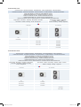
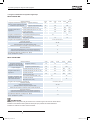
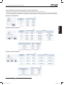
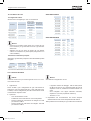
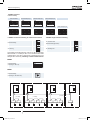
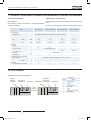
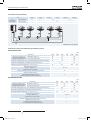
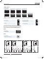
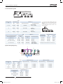
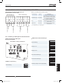
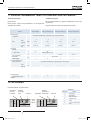
IVX Premium series
OUTDOOR UNIT · UNIDAD EXTERIOR · AUßENEINHEIT · UNITÉ EXTÉRIEURE · UNITÀ ESTERNA ·
UNIDADE EXTERIOR · UDENDRS AGGREGAT · BUITENTOESTEL · UTOMHUSENHET · ΕΞΩΤΕΡΙΚΗ ΜΟΝΑΔΑ
HEAT PUMP MODELS - MODELOS CON BOMBA DE CALOR
WÄRMEPUMPENMODELLE - MODÈLES POMPE À CHALEUR
MODELLI POMPA DI CALORE - MODELOS BOMBA DE CALOR
VARMEPUMPEMODELLER - MODELLEN MET WARMTEPOMP
MODELLER ENDAST FÖR KYLNINGSFUNKTION - ΜΟΝΤΕΛΑ ΜΕ ΑΝΤΛΙΑ ΘΕΡΜΟΤΗΤΑΣ
Single Phase - Monofásico - Einphasig - Monophasé - Monofase
Monofásico - Enfaset - Eenfasig - En fas - Μονοφασικά
Three Phase - Trifásico - Dreiphasig -
Triphasé -Trifase - Trifásico
Trefaset - Driefasig - Trefasig - Tριφασικά
1~ 230V 50Hz 3N~ 400V 50Hz
Unit Unit Unit
RAS-3HVNPE
RAS-4HVNPE RAS-4HNPE
RAS-5HVNPE RAS-5HNPE
RAS-6HVNPE RAS-6HNPE
RAS-8HNPE
RAS-10HNPE
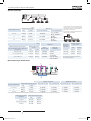
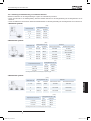
IVX Standard series
OUTDOOR UNIT · UNIDAD EXTERIOR · AUßENEINHEIT · UNITÉ EXTÉRIEURE · UNITÀ ESTERNA ·
UNIDADE EXTERIOR · UDENDRS AGGREGAT · BUITENTOESTEL · UTOMHUSENHET · ΕΞΩΤΕΡΙΚΗ ΜΟΝΑΔΑ
HEAT PUMP MODELS - MODELOS CON BOMBA DE CALOR
WÄRMEPUMPENMODELLE - MODÈLES POMPE À CHALEUR
MODELLI POMPA DI CALORE - MODELOS BOMBA DE CALOR
VARMEPUMPEMODELLER - MODELLEN MET WARMTEPOMP
MODELLER ENDAST FÖR KYLNINGSFUNKTION - ΜΟΝΤΕΛΑ ΜΕ ΑΝΤΛΙΑ ΘΕΡΜΟΤΗΤΑΣ
Single Phase - Monofásico - Einphasig - Monophasé -
Monofase - Monofásico - Enfaset - Eenfasig
En fas - Μονοφασικά
Three Phase - Trifásico - Dreiphasig - Triphasé -Trifase - Trifásico
Trefaset - Driefasig - Trefasig - Tριφασικά
1~ 230V 50Hz 3N~ 400V 50Hz
Unit Unit
RAS-4HVNCE RAS-4HNCE
RAS-5HVNCE RAS-5HNCE
RAS-6HVNCE RAS-6HNCE
RAS-8HNCE
RAS-10HNCE
_PMML0251A_r2.indb 8 06/02/2013 9:04:47

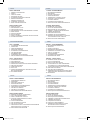
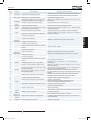
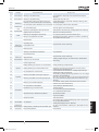
INDEX ÍNDICE
PART I OPERATION
1. GENERAL INFORMATION
2. SAFETY
3. PRODUCT GUIDE
4. IMPORTANT NOTICE
5. TRANSPORTATION AND HANDLING
6. BEFORE OPERATION
7. REMOTE CONTROLLER
8. AUTOMATIC CONTROLS
9. BASIC TROUBLESHOOTING
PART II INSTALLATION
10. NAME OF PARTS
11. REFRIGERANT CYCLE
12. UNITS INSTALLATION
13. REFRIGERANT PIPING & REFRIGERANT CHARGE
14. DRAIN PIPING
15. ELECTRIC WIRING
16. TEST RUNNING
17. SAFETY SUMMARY & CONTROL DEVICE SETTING
18. TROUBLESHOOTING
1ª PARTE: FUNCIONAMIENTO
1. INFORMACIÓN GENERAL
2. SEGURIDAD
3. GUÍA DEL PRODUCTO
4. AVISO IMPORTANTE
5. TRANSPORTE Y MANIPULACIÓN
6. ANTES DEL FUNCIONAMIENTO
7. CONTROL REMOTO
8. CONTROLES AUTOMÁTICOS
9. RESOLUCIÓN DE PROBLEMAS BÁSICOS
2ª PARTE: INSTALACIÓN
10. NOMBRE DE LAS PIEZAS
11. CICLO DE REFRIGERANTE
12. INSTALACIÓN DE LAS UNIDADES
13. TUBERÍA Y CARGA DE REFRIGERANTE
14. TUBERÍA DE DESAGÜE
15. CABLEADO ELÉCTRICO
16. PRUEBAS DE FUNCIONAMIENTO
17. RESUMEN DE SEGURIDAD Y AJUSTE DE
LOS DISPOSITIVOS DE CONTROL
18. RESOLUCIÓN DE PROBLEMAS
INHALTSVERZEICHNIS INDEX
TEIL I – BETRIEB
1. ALLGEMEINE INFORMATIONEN
2. SICHERHEIT
3. PRODUKTÜBERSICHT
4. WICHTIGER HINWEIS
5. TRANSPORT UND BEDIENUNG
6. VOR DEM BETRIEB
7. FERNBEDIENUNG
8. AUTOMATISCHE STEUERUNG
9. GRUNDLEGENDE FEHLERBESEITIGUNG
TEIL II – INSTALLATION
10. TEILEBEZEICHNUNG
11. KÜHLKREISLAUF
12. GERÄTEINSTALLATION
13. KÄLTEMITTELROHRE UND KÄLTEMITTELMENGE
14. ABFLUSSLEITUNGEN
15. KABELANSCHLUSS
16. TESTLAUF
17. SICHERHEITSÜBERSICHT UND EINSTELLUNG
DER STEUERGERÄTE
18. FEHLERBEHEBUNG
PARTIE I – FONCTIONNEMENT
1. INFORMATIONS GÉNÉRALES
2. SÉCURITÉ
3. GUIDE DU PRODUIT
4. REMARQUES IMPORTANTES
5. TRANSPORT ET MANIPULATION
6. AVANT L’UTILISATION
7. TÉLÉCOMMANDE
8. CONTRÔLES AUTOMATIQUES
9. DÉPANNAGE DE BASE
PARTIE II – INSTALLATION
10. NOMENCLATURE DES PIÈCES
11. CYCLE FRIGORIFIQUE
12. INSTALLATION DES UNITÉS
13. TUYAUTERIE DU FLUIDE FRIGORIGÈNE
ET CHARGE DU FLUIDE FRIGORIGÈNE
14. TUYAUTERIE D’ÉVACUATION DES CONDENSATS
15. CÂBLAGE ÉLECTRIQUE
16. TEST DE FONCTIONNEMENT
17. SOMMAIRE DES DISPOSITIFS DE SÉCURITÉ
& RÉGLAGE DES ORGANES DE CONTRÔLE
18. DEPANNAGE
INDICE ÍNDICE
PARTE I FUNZIONAMENTO
1. INFORMAZIONI GENERALI
2. SICUREZZA
3. GUIDA DEL PRODOTTO
4. NOTA IMPORTANTE
5. TRASPORTO E MOVIMENTAZIONE
6. PROCEDURA PRELIMINARE
7. CONTROLLO REMOTO
8. CONTROLLI AUTOMATICI
9. RISOLUZIONE DEI PROBLEMI MINORI
PART II INSTALLAZIONE
10. NOMENCLATURA DEI COMPONENTI
11. CICLO DI REFRIGERAZIONE
12. INSTALLAZIONE DELLE UNITÀ
13. LINEA DEL REFRIGERANTE E CARICA
DI REFRIGERANTE
14. LINEA DI DRENAGGIO
15. COLLEGAMENTI ELETTRICI
16. COLLAUDO DI PROVA
17. PRECAUZIONI PER LA SICUREZZA E IMPOSTAZIONI
DEI DISPOSITIVI DI CONTROLLO
18. RISOLUZIONE DEI PROBLEMI
PARTE I FUNCIONAMENTO
1. INFORMAÇÃO GERAL
2. SEGURANÇA
3. GUIA DO PRODUTO
4. NOTA IMPORTANTE
5. TRANSPORTE E MANUSEAMENTO
6. ANTES DE ARRANCAR A UNIDADE
7. CONTROLO REMOTO
8. CONTROLOS AUTOMÁTICOS
9. RESOLUÇÃO DE PROBLEMAS BÁSICOS
PARTE II INSTALAÇÃO
10. NOME DAS PEÇAS
11. CICLO DE REFRIGERAÇÃO
12. INSTALAÇÃO DAS UNIDADES
13. TUBAGEM E CARGA DE REFRIGERANTE
14. TUBAGEM DE ESGOTO
15. LIGAÇÕES ELÉCTRICAS
16. PROVA DE FUNCIONAMENTO
17. SUMÁRIO DE SEGURANÇA E AJUSTE
DE DISPOSITIVO DE CONTROLO
18. RESOLUÇÃO DE PROBLEMAS
_PMML0251A_r2.indb 9 06/02/2013 9:04:48

INDHOLDSFORTEGNELSE INHOUDSOPGAVE
DEL I - BETJENING
1. GENEREL INFORMATION
2. SIKKERHED
3. PRODUKTVEJLEDNING
4. VIGTIG MEDDELELSE
5. TRANSPORT OG HÅNDTERING
6. FØR DRIFT
7. FJERNBETJENING
8. AUTOMATISK BETJENING
9. BASIS FEJLFINDING
DEL II- MONTERING
10. NAVNE PÅ DELE
11. KØLEKREDSLØB
12. MONTERING AF ENHEDER
13. KØLERØRSYSTEM OG PÅFYLDNING AF
KØLEMIDDEL
14. AFLØBSRØR
15. ELEKTRISK LEDNINGSFØRING
16. TESTKØRSEL
17. OVERSIGT OVER INDSTILLINGER FOR
SIKKERHEDS- OG KONTROLENHEDER
18. FEJLFINDING
DEEL I BEDIENING
1. ALGEMENE INFORMATIE
2. VEILIGHEID
3. PRODUCTGIDS
4. BELANGRIJKE MEDEDELING
5. TRANSPORT EN HANTERING
6. VOORDAT U HET SYSTEEM IN GEBRUIK NEEMT
7. AFSTANDSBEDIENING
8. AUTOMATISCHE BESTURING
9. ELEMENTAIRE PROBLEMEN OPLOSSEN
DEEL II INSTALLATIE
10. NAMEN VAN ONDERDELEN
11. KOUDEMIDDELCYCLUS
12. INSTALLATIE VAN DE UNITS
13. KOELMIDDELLEIDINGEN & KOELMIDDEL VULLEN
14. AFVOERLEIDING
15. ELEKTRISCHE BEDRADING
16. PROEFDRAAIEN
17. VEILIGHEIDSSAMENVATTING &
BESTURINGSINRICHTING
18. PROBLEMEN OPLOSSEN
INNEHALLSFÖRTECKNING ΕΥΡΕΤΗΡΙΟ
DEL I ANVÄNDNING
1. ALLMÄN INFORMATION
2. SÄKERHET
3. PRODUKTGUIDE
4. VIKTIG ANMÄRKNING
5. TRANSPORT OCH HANTERING
6. FÖRE DRIFT
7. FJÄRRKONTROLL
8. AUTOMATIK KONTROLLANORDNING
9. GRUNDLÄGGANDE FELSÖKNING
DEL II INSTALLATION
10. DELARNAS NAMN
11. KYLMEDIETS CYKEL
12. INSTALLATION AV ENHETER
13. KYLRÖR & PÅFYLLNING AV KYLMEDIUM
14. DRÄNERINGSRÖR
15. ELEKTRISKA KABLAR
16. PROVKÖRNING
17. SÄKERHETSSAMMANFATTNING OCH
SÄKERHETSINSTÄLLNINGAR
18. FELSÖKNING
ΜΕΡΟΣ Ι – ΛΕΙΤΟΥΡΓΙΑ
1. ΓΕΝΙΚΕΣ ΠΛΗΡΟΦΟΡΙΕΣ
2. ΑΣΦΆΛΕΙΑ
3. ΟΔΗΓΟΣ ΠΡΟΪΟΝΤΟΣ
4. ΣΗΜΑΝΤΙΚΗ ΠΑΡΑΤΗΡΗΣΗ
5. ΜΕΤΑΦΟΡΆ ΚΑΙ ΧΕΙΡΙΣΜΌΣ
6. ΠΡΙΝ ΤΗ ΛΕΙΤΟΥΡΓΙΑ
7. ΧΕΙΡΙΣΤΗΡΙΟ
8. ΑΥΤΟΜΑΤΕΣ ΛΕΙΤΟΥΡΓΙΕΣ
9. ΑΝΤΙΜΕΤΩΠΙΣΗ ΠΡΟΒΛΗΜΑΤΩΝ - ΒΑΣΙΚΑ
ΜΕΡΟΣ ΙΙ – ΕΓΚΑΤΑΣΤΑΣΗ
10. ΟΝΟΜΑΤΑ ΕΞΑΡΤΗΜΑΤΩΝ
11. ΚΥΚΛΟΣ ΨΥΞΗΣ
12. ΕΓΚΑΤΑΣΤΑΣΗ ΕΣΩΤΕΡΙΚΩΝ ΜΟΝΑΔΩΝ
13. ΣΩΛΗΝΩΣΕΙΣ ΨΥΚΤΙΚΟΥ & ΠΛΗΡΩΣΗ ΜΕ
ΨΥΚΤΙΚΟ ΜΕΣΟ
14. ΣΩΛΗΝΩΣΕΙΣ ΑΠΟΧΕΤΕΥΣΗΣ
15. ΗΛΕΚΤΡΙΚΗ ΚΑΛΩΔΙΩΣΗ
16. ΔΟΚΙΜΑΣΤΙΚΗ ΛΕΙΤΟΥΡΓΙΑ
17. ΣΥΝΟΠΤΙΚΕΣ ΠΡΟΦΥΛΑΞΕΙΣ ΑΣΦΑΛΕΙΑΣ
& ΡΥΘΜΙΣΕΙΣ ΣΥΣΚΕΥΩΝ ΕΛΕΓΧΟΥ
18. ΑΝΤΙΜΕΤΩΠΙΣΗ ΠΡΟΒΛΗΜΑΤΩΝ
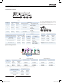
EN English Original version
ES Español Versión traducida
DE Deutsch Übersetzte Version
FR Français Version traduite
IT Italiano Versione tradotta
PT Português Versão traduzidal
DA Dansk Oversat version
NL Nederlands Vertaalde versie
SV Svenska Översatt version
EL ΕΛΛΗΝΙΚΑ Μεταφρασμένη έκδοση
_PMML0251A_r2.indb 10 06/02/2013 9:04:48

PMML0251A rev.2 - 02/2013
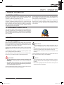
General information
11
ENGLISH
PART I - OPERATION
1.2 ENVIRONMENT-FRIENDLY UNITS
1 GENERAL INFORMATION
1.1 GENERAL NOTES
No part of this publication may be reproduced, copied, led or
transmitted in any shape or form without the permission of HI-
TACHI Air Conditioning Products Europe, S.A.
Within the policy of continuous improvement of its products, HI-
TACHI Air Conditioning Products Europe, S.A. reserves the right
to make changes at any time without prior notication and without
being compelled to introducing them into products subsequently
sold. This document may therefore have been subject to amend-
ments during the life of the product.
HITACHI makes every effort to offer correct, up-to-date documen-
tation. Despite this, printing errors cannot be controlled by HI-
TACHI and are not its responsibility.
As a result, some of the images or data used to illustrate this
document may not refer to specic models. No claims will be ac-
cepted based on the data, illustrations and descriptions included
in this manual.
This range of HITACHI outdoor units uses environmentally-friend-
ly R410A gas refrigerant, and the RoHS and Greed Dot regula-
tions are applied throughout the manufacturing and installation
process to reect HITACHI’s awareness of environmental respect
and commitment.
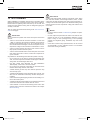
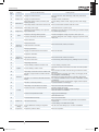
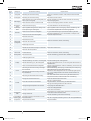
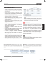
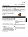
2 SAFETY
2.1 APPLIED SYMBOLS
During normal air conditioning system design work or unit instal-
lation, greater attention must be paid in certain situations requir-
ing particular care in order to avoid injuries an damage to the unit,
the installation or the building or property.
Situations that jeopardise the safety of those in the surrounding
area or that put the unit itself a risk will be clearly indicated in this
manual.
To indicate these situations, a series of special symbols will be
used to clearly identify these situations.
Pay close attention to these symbols and to the messages follow-
ing them, as your safety and that of others depends on it.
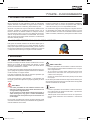
D A N G E R
• Thetextfollowingthissymbolcontainsinformationand
instructionsrelatingdirectlytoyoursafetyandphysical
wellbeing.
• Nottakingtheseinstructionsintoaccountcouldleadto
serious,veryseriousorevenfatalinjuriestoyouandoth-
ersintheproximitiesoftheunit.
In the text following the danger symbol you can also nd informa-
tion on safe procedures during unit installation.
C A U T I O N
• The text following this symbol contains information and in-
structions relating directly to your safety and physical wellbe-
ing.
• Not taking these instructions into account could lead to minor
injuries to you and others in the proximities of the unit.
• Not taking these instructions into account could lead to unit
damage.
In the text following the caution symbol you can also nd informa-
tion on safe procedures during unit installation.
N O T E
• The text following this symbol contains information or instruc-
tions that may be of use or that require a more thorough ex-
planation.
• Instructions regarding inspections to be made on unit parts or
systems may also be included.
_PMML0251A_r2.indb 11 06/02/2013 9:04:49

PMML0251A rev.2 - 02/201312
Product guide
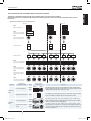
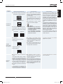
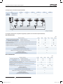
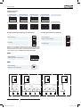
3 PRODUCT GUIDE
3.1 CLASSIFICATION OF IVX OUTDOOR UNITS MODELS
D A N G E R
Do not pour water into the indoor or outdoor unit. These
productsareequippedwithelectricalparts.Ifwatercontacts
withelectricalcomponentsthenitwillcauseaseriouselec-
tricalshock.
Donottouch oradjustsafetydevices insidetheindooror
outdoor units. If these devices are touched or adjusted, it
maycauseaseriousaccident.
Donotopentheservicecoveroraccesstheindoororout-
doorunitswithoutdisconnectingthemainpowersupply.
IncaseofreTurnOFFthemainswitch,putoutthereat
onceandcontactyourservicecontractor.
C A U T I O N
Do not use any sprays such as insecticide, lacquer, hair spray or
other ammable gases within approximately one (1) meter from
the system.
If circuit breaker or fuse is often activated, stop the system and
contact your service contractor.
Do not make service or inspections tasks by yourself. This works
must be performed by qualied service person.
Do not put any strange material (sticks, etc...) into the air inlet and
outlet. These units have high speed rotating fans and it is danger-
ous that any object touches them.
Refrigerant leakage can cause difculty with breathing due to in-
sufcient air.
This appliance must be used only by adult and capable people,
having received the technical information or instructions to handle
properly and safely this appliance.
Children should be supervised to ensure that they do not play
with the appliance.
N O T E
It is recommended to ventilate the room every 3 or 4 hours.
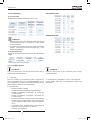
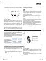
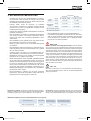
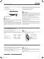
2.2 ADDITIONAL INFORMATION ABOUT SAFETY
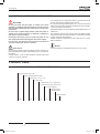
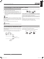
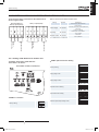
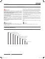
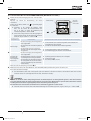
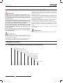
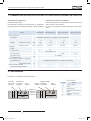
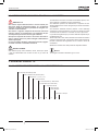
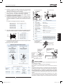
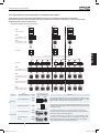
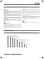
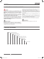
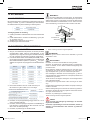
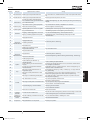
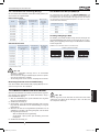
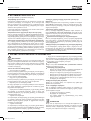
Unit type (Outdoor unit): RAS
Position-separating hyphen (xed)
Capacity (HP): 3, 4, 5, 6, 8, 10
H = Heat pump
V = Single phase unit (1~ 230V 50Hz)
- = Three phase unit (3N~ 400V 50Hz)
N = R410A refrigerant
P: Premium series
C: Standard series
E = Made in Europe
XXX – XX H (X) N X X
_PMML0251A_r2.indb 12 06/02/2013 9:04:49

PMML0251A rev.2 - 02/2013
Important notice
13
ENGLISH
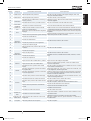
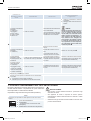
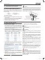
4 IMPORTANT NOTICE
• Verify, in accordance with the manuals which appear in the
outdoor and indoor units, that all the information required for
the correct installation of the system is included. If this is not
the case, contact your distributor.
• HITACHI pursues a policy of continuing improvement
in design and performance of products. The right is therefore
reserved to vary specications without notice.
• HITACHI cannot anticipate every possible circumstance that
might involve a potential hazard.
• This air conditioner has been designed for standard air condi-
tioning for human beings. For use in other applications, please
contact your HITACHI dealer or service contractor.
• No part of this manual may be reproduced without written per-
mission.
• If you have any questions, contact your service contractor of
HITACHI.
• This manual gives a common description and information
for this air conditioner which you operate as well as for other
models.
• Check and make sure that the explanations of each part of
this manual correspond to your air conditioner model.
• Refer to the models codication to conrm the main charac-
teristics of your system.
• Signal words (DANGER, WARNING and CAUTION) are used
to identify levels of hazard seriousness. Denitions for iden-
tifying hazard levels are provided below with their respective
signal words.
• It is assumed that this unit will be operated and serviced by
English speaking people. If this is not the case, the customer
should add safety, caution and operating signs in the native
language of the personal.
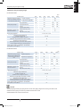
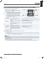
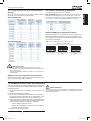
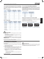
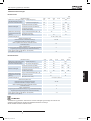
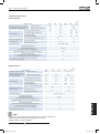
• This air conditioner has been designed for the following tem-
perature. Operate the air conditioner within this range:
Temperature
Maximum Minimum
Cooling
Mode
Indoor 32°C DB/23°C WB 21°C DB/15°C WB
Outdoor 46 ºC DB -5 °C DB
Heating
Mode
Indoor 27 °C DB 15 °C DB
Outdoor 15 °C WB -20 °C WB
DB: Dry Bulb Temperature
WB: Wet Bulb Temperature
• These operations modes are controlled by the remote control
switch.
• This manual should be considered as a permanent part of the
air conditioner. This manual gives a common description and
information for this air conditioner which you operate as well
as for other models.
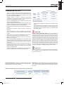
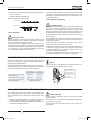
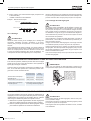
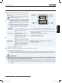
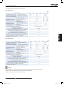
D A N G E R
Pressure Vessel and Safety Device: This air conditioner is
equipped with a high pressure vessel under PED (Pressure Equip-
ment Directive). The pressure vessel has been designed and test-
ed before shipment according to PED. Also, in order to prevent the
system from an abnormal pressure, a high pressure switch, which
needs no eld adjustment, is utilized in the refrigeration system.
Therefore, this air conditioner is protected from abnormal pres-
sures. However, if abnormally high pressure is applied to the re-
frigeration cycle including the high pressure vessel(s), it will result
in serious injury or death due to explosion of the pressure vessel.
Do not apply a pressure higher than the following pressure to the
system, by modifying or changing the high pressure switch.
C A U T I O N
This unit is designed for commercial and light industrial applica-
tion. If installed in house hold appliance, it could cause electro-
magnetic interference.
Start-up and Operation: Check to ensure that all the stop valves
are fully opened and no obstacle exists at the inlet/outlet sides
before start-up and during the operation.
Maintenance: Periodically check the high pressure side pres-
sure. If the pressure is higher than the maximum allowable pres-
sure, stop the system and clean the heat exchanger or remove
the cause.
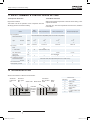
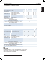
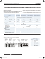
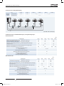
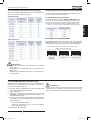
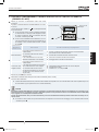
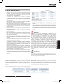
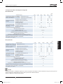
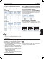
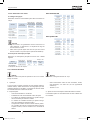
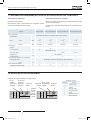
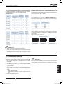
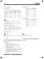
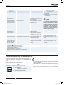
Maximum Allowable Pressure and High Pressure Cut-out Value:
Outdoor Unit Model Refrigerant
Maximum Allowable
Pressure (MPa)
High Pressure Switch
Cut-out Value (MPa)
RAS-(3-10)H(V)N(P/C)E R410A 4.15 4.00 ~ 4.10
_PMML0251A_r2.indb 13 06/02/2013 9:04:50

PMML0251A rev.2 - 02/201314
Transportation and handling
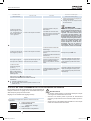
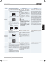
N O T E
The label for the vessel under PED are attached on the high pres-
sure vessel. The pressure vessel capacity and vessel category
are indicated on the vessel.
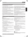
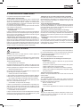
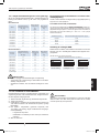
Location of High Pressure Switch
Compressor
N O T E
The high pressure switch is indicated on the electrical wiring di-
agram in the outdoor unit as PSH connected to printed circuit
board (PCB1) in the outdoor unit
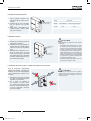
Structure of High Pressure Switch
Contact Point Pressure Detected
Connected to the electrical wire
D A N G E R
Do notchange the high-pressureswitch locally or change
thehighpressurecut-outsetvaluelocally.Ifchanged,itwill
causeseriousinjuryordeathduetoexplosion.
Donotattempttoturnservicevalverodbeyonditsstop.
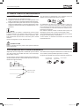
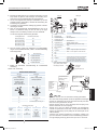
6 BEFORE OPERATION
C A U T I O N
Supply electrical power to the system for approximately 12 hours be-
fore start-up or a long shutdown. Do not start the system immediately
after power supply, it may cause a compressor failure because the
compressor is not heated well.
When the system is started after a shutdown longer that approxi-
mately 3 months, it is recommended to check the system by your
service contractor.
Turn OFF the main switch when the system is to be stopped for a
long period of time: If the main switch is not turned OFF, electric-
ity will be used, because the oil heater is always energised during
compressor stopping.
Make sure that the outdoor unit is not covered with snow or ice.
If covered, remove it by using hot water (approximately 50°C). If
the water temperature is higher that 50 °C, it will cause damage
to plastic parts.
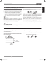
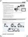
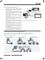
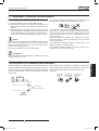
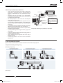
7 REMOTE CONTROLLER
It is advisable to use PC-ART or PC-ARF remote controller (both optional). For more information about it installation and operation,
please refer to its corresponding Installation and Operation Manuals.
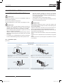
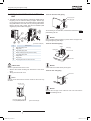
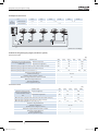
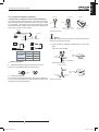
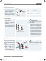
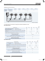
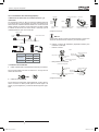
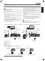
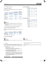
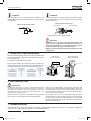
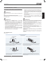
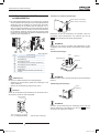
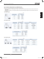
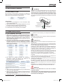
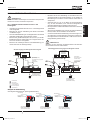
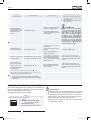
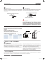
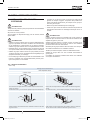
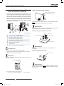
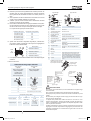
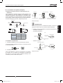
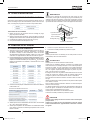
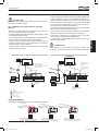
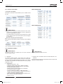
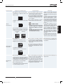
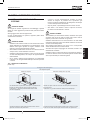
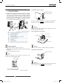
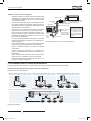
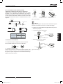
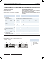
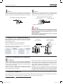
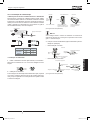
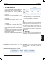
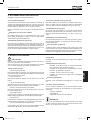
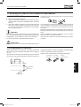
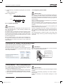
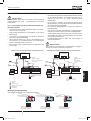
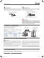
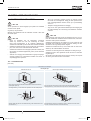
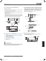
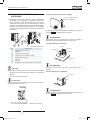
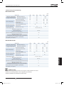
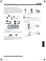
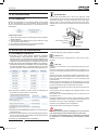
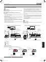
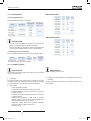
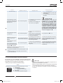
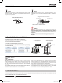
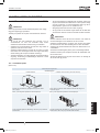
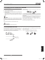
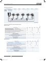
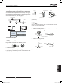
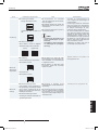
5 TRANSPORTATION AND HANDLING
When hanging the unit, ensure a balance of the unit, check safety
and lift it up smoothly
Do not remove any packing materials.
Hang the unit under packing condition with two ropes.
For safety reasons ensure that the outdoor unit is lifted smoothly
and does not lean
Model
Gross Weight
(kg)
RAS-3HVNPE
77
RAS-(4-6)H(V)NPE
116
RAS-4H(V)NCE
78
Model
Gross Weight
(kg)
RAS-(5-6)H(V)NCE
90
RAS-8HN(P/C)E
149
RAS-10HN(P/C)E
151
RAS-3HVNP RAS-(4-6)H(V)NPE
RAS-(4-6)H(V)NCE RAS-(8-10)HN(P/C)E
0.7 -1.0 m
> 60º
_PMML0251A_r2.indb 14 06/02/2013 9:04:51

PMML0251A rev.2 - 02/2013
Automatic controls
15
ENGLISH
8 AUTOMATIC CONTROLS
The system is equipped with the following functions.
Three minute guard
The compressor remains off for at least 3 minutes once it has
stopped. If the system is started within approximately 3 minutes
after it has stopped, the RUN indicator is activated. However, the
cooling operation or the heating operation remains off and does
not start until after 3 minutes has elapsed.
Operation may stop for 6 minutes maximum to protect compressor.
Frost prevention during cooling operation
When the system is operated in a low temperature room, the
cooling operation may be changed to fan operation for a while to
avoid frost formation on the indoor heat exchanger.
Automatic restart after power failure
If the power supply is interrupted for short periods of time (up to
2 seconds) the Remote Control switch will retain the settings and
the unit will restart when the power is restored. If Automatic Re-
start is required after periods of lost power supply in excess of 2
seconds please contact your distributor (optional function).
Slow air control during heating operation
Can be setting than when the compressor is stopped while the
thermostat is OFF, or the system is performing the automatic de-
frosting operation, the fan speed is set at the slow position.
Automatic defrosting cycle
When the heating operation is stopped by pressing RUN/STOP
switch, frosting on the outdoor unit is checked and the defrosting
operation may be performed for the maximum of 10 minutes.
Prevention of overload operation
When the outdoor temperature is too high during heating opera-
tion, heating operation is stopped due to activation of the outdoor
thermistor until the temperature becomes low.
Hot start during heating operation
To prevent cold air discharge, the fan speed is controlled from
the slow position to the set position according to the discharge air
temperature. At this time the lover is xed horizontally.
9 BASIC TROUBLESHOOTING
C A U T I O N
When water leakage from the indoor unit occurs, stop the opera-
tion and contact your contractor
When you smell or white smoke occurs from the unit, stop the
system and contact your contractor.
This is not abnormal
• Sound from deforming Part
During system starting or stopping, and abrading sound might
be heard. However, this is due to thermal deformation of plastic
parts. It is not abnormal.
• Refrigerant Flow Sound
While the system is being started or stopping, sound from the
refrigerant ow may be heard.
• Smells from Indoor Unit
Smell adheres on indoor unit after a long period of time. Clean the
air lter and panels or make a good ventilation.
• Steam from Outdoor Heat Exchanger
During defrosting operation, ice on the outdoor heat exchanger is
melted, resulting in making steam.
• Dew on Air Panel
When the cooling operation continues for a long period of time
under high humidity conditions (higher than 27°C DB/80% R.H.),
dew can form on the air panel.
• Dew on Cabinet
When the cooling operation continues for a long period of timer
(higher than 27°C DB/80% R.H.), dew can form on the cabinet.
• Sound for the indoor unit heat exchanger
During the cooling operation, a sound may be heard from the in-
door unit heat exchanger due to water freezing or melting.
No operation
Check whether the SET TEMPERATURE is set at the correct
temperature.
Not cooling well or heating well
- Check for obstruction of air ow of the outside or inside
units.
- Check if too much heat source exists in the room.
- Check if the air lter is clogged with dust.
- Check to see if the doors or windows are opened or not.
- Check if the temperature condition is not within the operat-
ing range.
Abnormal swing louver’s position
Check if the four louver’s position at the air outlet are in same
position.
If trouble still remains...
If the trouble still remains even after checking the above items,
contact your service contractor and inform the following data:
- Unit Model Name
- Content of Trouble
- Alarm Code no. on Liquid Crystal Display
N O T E
Except for a long period of shutdown, keep the main switch ON,
since the oil heater is energised when the compressor is stopped.
_PMML0251A_r2.indb 15 06/02/2013 9:04:51

PMML0251A rev.2 - 02/201316
Name of parts
PART II - INSTALLATION
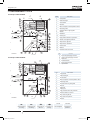
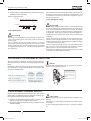
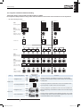
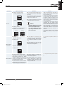
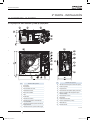
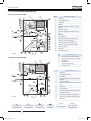
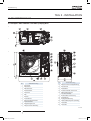
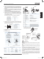
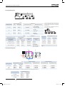
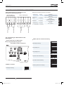
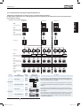
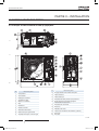
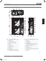
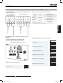
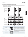
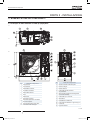
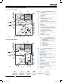
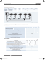
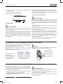
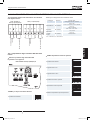
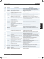
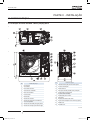
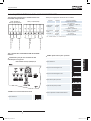
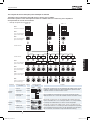
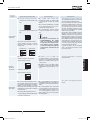
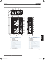
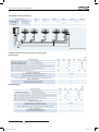
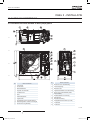
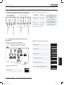
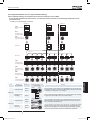
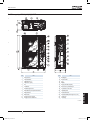
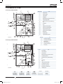
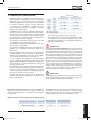
10 NAME OF PARTS
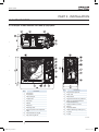
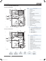
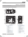
10.1 Example of RAS-3HVNPE and RAS-(4-6)H(V)NCE
No. Part Name
1 Compressor
2 Accumulator
3 Heat exchanger
4 Propeller fan
5 Fan motor
6 Strainer
7 Distributor
8 Reversing valve
9
Micro-computer control expansion
valve
10 Solenoid valve for hot gas
11 Stop valve for gas line
No. Part Name
12 Stop valve for liquid line
13 Check Joint
14 Electrical box
15 High pressure switch for protection
16
Sensor for refrigerant pressure
(RAS-3HVNPE only)
17 Pressure switch for control
18 Silencer
19 Crankcase heater
20 Vibration absorbing rubber (3pcs.)
21 Air outlet
22 Air inlet
7T143458
_PMML0251A_r2.indb 16 06/02/2013 9:04:53

PMML0251A rev.2 - 02/2013
Name of parts
17
ENGLISH
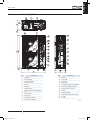
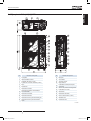
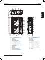
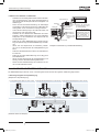
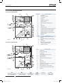
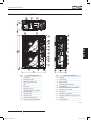
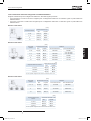
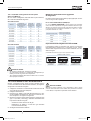
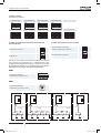
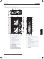
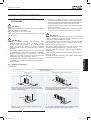
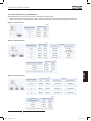
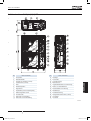
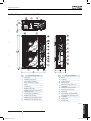
10.2 Example of RAS-(4-6)H(V)NPE
No. Part Name
1 Compressor
2 Heat exchanger
3 Propeller fan (2pcs.)
4 Fan motor (2pcs.)
5 Strainer
6 Distributor
7 Reversing Valve
8
Micro-computer control expansion
valve
9 Solenoid valve
10 Check valve
11 Stop valve for gas line
12 Stop valve for liquid line
No. Part Name
13 Receiver
14 Accumulator
15 Check joint
16 Electrical box
17 High pressure switch for protection
18 Sensor for refrigerant pressure
19 Pressure switch for control
20 Silencer
21 Crankcase heater
22 Vibration absorbing rubber (4pcs.)
23 Air outlet
24 Air inlet
7T143459
_PMML0251A_r2.indb 17 06/02/2013 9:04:54

PMML0251A rev.2 - 02/201318
Refrigerant cycle
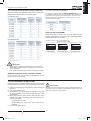
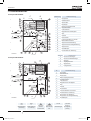
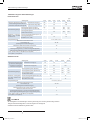
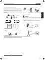
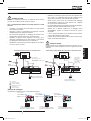
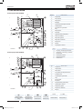
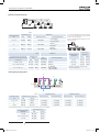
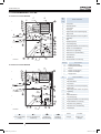
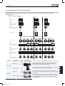
11 REFRIGERANT CYCLE
Example of RAS-4HVNPE:
D
C
B
A
E
7S138311
F
Mark Part name
1 Compressor
2 Heat exchanger
3 Accumulator
4 Receiver
5 Micro-computer control expansion valve
6 Reversing valve
7 Solenoid valve for gas bypass
8 Strainer
9 Distributor
10 Check joint
11 High pressure switch for protection
12 Sensor for refrigerant pressure
13 Stop valve for gas line
14 Stop valve for liquid line
15 Check valve
16 Silencer
17 Pressure switch for control
Example of RAS-4HVNCE:
A
B
C
D
F
F
E
7S136195
No. Part name
1 Compressor
2 Heat exchanger
3 Accumulator
4 Micro-Computer control expansion valve
5 Reversing valve
6 Solenoid valve for gas bypass
7 Strainer
8 Distributor
9 Check joint
10 High pressure switch for protection
11 Pressure switch for control
12 Stop valve for gas line
13 Stop valve for liquid line
14 Silencer
R410A 4.15 MPa
Refrigerant ow
or cooling
Refrigerant ow
for heating
Connection by
are nut
Connection by
welding
Gas refrigerant
Leakage test
pressure
Mark Part name
A Gas line refrigerant piping connection
B Liquid line refrigerant piping connection
C Outdoor unit
D Ambient thermistor
E Discharge gas thermistor
F Pipe thermistor
_PMML0251A_r2.indb 18 06/02/2013 9:04:56

PMML0251A rev.2 - 02/2013
Units installation
19
ENGLISH
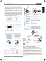
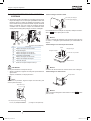
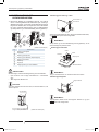
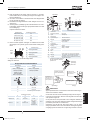
12 UNITS INSTALLATION
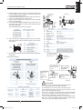
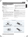
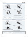
12.1 OUTDOOR UNITS INSTALLATION
C A U T I O N
Transport the products as close to the installation location as
practical before unpacking.
Do not put any material on the products.
Apply four lifting wires on to the outdoor, when lifting it by crane
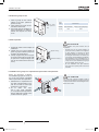
C A U T I O N
• Install the outdoor unit with sufcient clearance around it for
operation and maintenance as shown in the next gures.
Install the outdoor unit where good ventilation is available
• Do not install the outdoor unit where is a high level of oil mist,
salty air or sulphurous atmosphere.
• Install the outdoor unit as far as practical (being at least 3
meters) from electromagnetic wave radiator (such as medical
equipment).
• For cleaning, use noninammable and nontoxic cleaning liq-
uid. Use of inammable agent may cause explosion or re.
• Work with sufcient ventilation, for working in an enclosed
space may cause oxygen deciency. Toxic gas may be pro-
duced when cleaning agent is heated to high temperature by,
e.g., being exposed to re.
• Cleaning liquid shall be collected after cleaning.
• Pay attention not to clamp cables when attaching the service
cover to avoid electric shock or re.
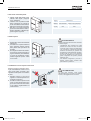
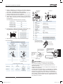
C A U T I O N
Keep clearance between the units of more than 100mm, and
avoid obstacles that may hamper air intake, when installing more
than one units together.
Install the outdoor unit in the shade or not exposed to direct sun-
shine or direct radiation from high temperature heat source.
Do not install the Outdoor Unit in a space where a seasonal wind
directly blows to the Outdoor fan.
Check to ensure that the foundation is at, level and sufciently
strong.
Install the unit in a restricted area not accessible by the general
public
Aluminium ns have very sharp edges. Pay attention to the ns
to avoid injury.
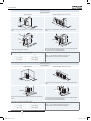
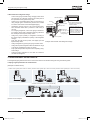
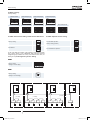
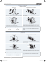
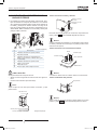
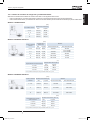
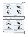
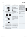
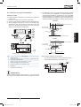
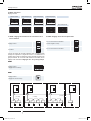
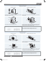
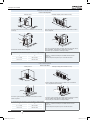
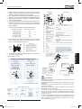
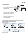
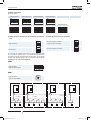
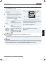
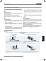
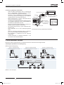
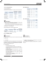
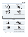
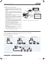
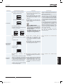
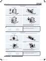
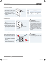
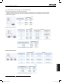
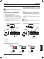
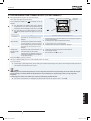
12.1.1 Installation space
(Unit: mm)
Blocked in Inlet Side
Upper Side Open
Single Installation Multiple Installation (Two units or more)
200 or more of the back space is acceptable when the right and left
sides are open.
Dimensions in ( ) shows numbers especially for RAS-3HVN(P/C)E.
Allow 100 mm of space between units. Leave open both right and left
sides.
Dimensions in ( ) shows numbers especially for RAS-3HVN(P/C)E.
Be sure to use the fan direction guide. Leave open both right and left
sides.
Be sure to use the fan direction guide. Allow 100 mm of space between
units. Leave open both right and left sides.
_PMML0251A_r2.indb 19 06/02/2013 9:04:57

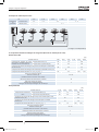
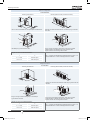
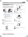
PMML0251A rev.2 - 02/201320
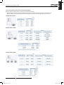
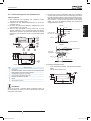
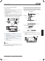
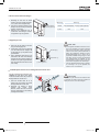
Units installation
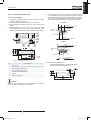
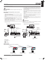
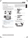
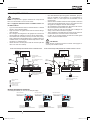
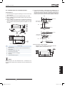
Blocked in Inlet Side
Upper Side Blocked
Single Installation Multiple Installation (Two units or more)
100 mm or more of the side space is acceptable on the service cover
side.
Allow 100 mm of space between units. Leave open both right and left
sides..
Leave open both right and left sides.
Be sure to use the fan direction guide. Allow 100 mm of space between
units. Leave open both right and left sides.
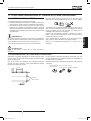
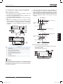
No more than 2 units for multiple installation.
The length A is as shown in the following table:
L A
0 < L ≤ 1/2H 600 or greater
1/2H < L≤ H 1400 or greater
When L > H use a base for outdoor unit to make L ≤ H.
Close the base not to allow the outlet air bypassed.
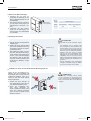
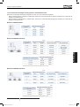
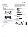
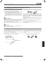
Outlet Side Blocked
Upper Side Open
Single Installation Multiple Installation (Two units or more)
Allow 100 mm of space between units. Both right and left sides shall be
open.
Be sure to use the fan direction guide. Leave open both right and left
sides.
Be sure to use the fan direction guide. Allow 100 mm of space between
units. Leave open both right and left sides.
No more than 2 units for multiple installation.
The length A is as shown in the following table:
L A
0 < L ≤ 1/2H 600 or greater
1/2H < L≤ H 1400 or greater
When L > H use a base for outdoor unit to make L ≤ H.
Close the base not to allow the outlet air bypassed.
_PMML0251A_r2.indb 20 06/02/2013 9:04:58
La pagina sta caricando ...
La pagina sta caricando ...
La pagina sta caricando ...
La pagina sta caricando ...
La pagina sta caricando ...
La pagina sta caricando ...
La pagina sta caricando ...
La pagina sta caricando ...
La pagina sta caricando ...
La pagina sta caricando ...
La pagina sta caricando ...
La pagina sta caricando ...
La pagina sta caricando ...
La pagina sta caricando ...
La pagina sta caricando ...
La pagina sta caricando ...
La pagina sta caricando ...
La pagina sta caricando ...
La pagina sta caricando ...
La pagina sta caricando ...
La pagina sta caricando ...
La pagina sta caricando ...
La pagina sta caricando ...
La pagina sta caricando ...
La pagina sta caricando ...
La pagina sta caricando ...
La pagina sta caricando ...
La pagina sta caricando ...
La pagina sta caricando ...
La pagina sta caricando ...
La pagina sta caricando ...
La pagina sta caricando ...
La pagina sta caricando ...
La pagina sta caricando ...
La pagina sta caricando ...
La pagina sta caricando ...
La pagina sta caricando ...
La pagina sta caricando ...
La pagina sta caricando ...
La pagina sta caricando ...
La pagina sta caricando ...
La pagina sta caricando ...
La pagina sta caricando ...
La pagina sta caricando ...
La pagina sta caricando ...
La pagina sta caricando ...
La pagina sta caricando ...
La pagina sta caricando ...
La pagina sta caricando ...
La pagina sta caricando ...
La pagina sta caricando ...
La pagina sta caricando ...
La pagina sta caricando ...
La pagina sta caricando ...
La pagina sta caricando ...
La pagina sta caricando ...
La pagina sta caricando ...
La pagina sta caricando ...
La pagina sta caricando ...
La pagina sta caricando ...
La pagina sta caricando ...
La pagina sta caricando ...
La pagina sta caricando ...
La pagina sta caricando ...
La pagina sta caricando ...
La pagina sta caricando ...
La pagina sta caricando ...
La pagina sta caricando ...
La pagina sta caricando ...
La pagina sta caricando ...
La pagina sta caricando ...
La pagina sta caricando ...
La pagina sta caricando ...
La pagina sta caricando ...
La pagina sta caricando ...
La pagina sta caricando ...
La pagina sta caricando ...
La pagina sta caricando ...
La pagina sta caricando ...
La pagina sta caricando ...
La pagina sta caricando ...
La pagina sta caricando ...
La pagina sta caricando ...
La pagina sta caricando ...
La pagina sta caricando ...
La pagina sta caricando ...
La pagina sta caricando ...
La pagina sta caricando ...
La pagina sta caricando ...
La pagina sta caricando ...
La pagina sta caricando ...
La pagina sta caricando ...
La pagina sta caricando ...
La pagina sta caricando ...
La pagina sta caricando ...
La pagina sta caricando ...
La pagina sta caricando ...
La pagina sta caricando ...
La pagina sta caricando ...
La pagina sta caricando ...
La pagina sta caricando ...
La pagina sta caricando ...
La pagina sta caricando ...
La pagina sta caricando ...
La pagina sta caricando ...
La pagina sta caricando ...
La pagina sta caricando ...
La pagina sta caricando ...
La pagina sta caricando ...
La pagina sta caricando ...
La pagina sta caricando ...
La pagina sta caricando ...
La pagina sta caricando ...
La pagina sta caricando ...
La pagina sta caricando ...
La pagina sta caricando ...
La pagina sta caricando ...
La pagina sta caricando ...
La pagina sta caricando ...
La pagina sta caricando ...
La pagina sta caricando ...
La pagina sta caricando ...
La pagina sta caricando ...
La pagina sta caricando ...
La pagina sta caricando ...
La pagina sta caricando ...
La pagina sta caricando ...
La pagina sta caricando ...
La pagina sta caricando ...
La pagina sta caricando ...
La pagina sta caricando ...
La pagina sta caricando ...
La pagina sta caricando ...
La pagina sta caricando ...
La pagina sta caricando ...
La pagina sta caricando ...
La pagina sta caricando ...
La pagina sta caricando ...
La pagina sta caricando ...
La pagina sta caricando ...
La pagina sta caricando ...
La pagina sta caricando ...
La pagina sta caricando ...
La pagina sta caricando ...
La pagina sta caricando ...
La pagina sta caricando ...
La pagina sta caricando ...
La pagina sta caricando ...
La pagina sta caricando ...
La pagina sta caricando ...
La pagina sta caricando ...
La pagina sta caricando ...
La pagina sta caricando ...
La pagina sta caricando ...
La pagina sta caricando ...
La pagina sta caricando ...
La pagina sta caricando ...
La pagina sta caricando ...
La pagina sta caricando ...
La pagina sta caricando ...
La pagina sta caricando ...
La pagina sta caricando ...
La pagina sta caricando ...
La pagina sta caricando ...
La pagina sta caricando ...
La pagina sta caricando ...
La pagina sta caricando ...
La pagina sta caricando ...
La pagina sta caricando ...
La pagina sta caricando ...
La pagina sta caricando ...
La pagina sta caricando ...
La pagina sta caricando ...
La pagina sta caricando ...
La pagina sta caricando ...
La pagina sta caricando ...
La pagina sta caricando ...
La pagina sta caricando ...
La pagina sta caricando ...
La pagina sta caricando ...
La pagina sta caricando ...
La pagina sta caricando ...
La pagina sta caricando ...
La pagina sta caricando ...
La pagina sta caricando ...
La pagina sta caricando ...
La pagina sta caricando ...
La pagina sta caricando ...
La pagina sta caricando ...
La pagina sta caricando ...
La pagina sta caricando ...
La pagina sta caricando ...
La pagina sta caricando ...
La pagina sta caricando ...
La pagina sta caricando ...
La pagina sta caricando ...
La pagina sta caricando ...
La pagina sta caricando ...
La pagina sta caricando ...
La pagina sta caricando ...
La pagina sta caricando ...
La pagina sta caricando ...
La pagina sta caricando ...
La pagina sta caricando ...
La pagina sta caricando ...
La pagina sta caricando ...
La pagina sta caricando ...
La pagina sta caricando ...
La pagina sta caricando ...
La pagina sta caricando ...
La pagina sta caricando ...
La pagina sta caricando ...
La pagina sta caricando ...
La pagina sta caricando ...
La pagina sta caricando ...
La pagina sta caricando ...
La pagina sta caricando ...
La pagina sta caricando ...
La pagina sta caricando ...
La pagina sta caricando ...
La pagina sta caricando ...
La pagina sta caricando ...
La pagina sta caricando ...
La pagina sta caricando ...
La pagina sta caricando ...
La pagina sta caricando ...
La pagina sta caricando ...
La pagina sta caricando ...
La pagina sta caricando ...
La pagina sta caricando ...
La pagina sta caricando ...
La pagina sta caricando ...
La pagina sta caricando ...
La pagina sta caricando ...
La pagina sta caricando ...
La pagina sta caricando ...
La pagina sta caricando ...
La pagina sta caricando ...
La pagina sta caricando ...
La pagina sta caricando ...
La pagina sta caricando ...
La pagina sta caricando ...
La pagina sta caricando ...
La pagina sta caricando ...
La pagina sta caricando ...
La pagina sta caricando ...
La pagina sta caricando ...
La pagina sta caricando ...
La pagina sta caricando ...
La pagina sta caricando ...
La pagina sta caricando ...
La pagina sta caricando ...
La pagina sta caricando ...
La pagina sta caricando ...
La pagina sta caricando ...
La pagina sta caricando ...
La pagina sta caricando ...
La pagina sta caricando ...
La pagina sta caricando ...
La pagina sta caricando ...
La pagina sta caricando ...
La pagina sta caricando ...
La pagina sta caricando ...
La pagina sta caricando ...
La pagina sta caricando ...
La pagina sta caricando ...
La pagina sta caricando ...
La pagina sta caricando ...
La pagina sta caricando ...
La pagina sta caricando ...
La pagina sta caricando ...
La pagina sta caricando ...
La pagina sta caricando ...
La pagina sta caricando ...
La pagina sta caricando ...
La pagina sta caricando ...
La pagina sta caricando ...
La pagina sta caricando ...
La pagina sta caricando ...
La pagina sta caricando ...
La pagina sta caricando ...
La pagina sta caricando ...
La pagina sta caricando ...
La pagina sta caricando ...
La pagina sta caricando ...
La pagina sta caricando ...
La pagina sta caricando ...
La pagina sta caricando ...
La pagina sta caricando ...
La pagina sta caricando ...
La pagina sta caricando ...
La pagina sta caricando ...
La pagina sta caricando ...
La pagina sta caricando ...
La pagina sta caricando ...
La pagina sta caricando ...
La pagina sta caricando ...
La pagina sta caricando ...
La pagina sta caricando ...
La pagina sta caricando ...
La pagina sta caricando ...
La pagina sta caricando ...
La pagina sta caricando ...
La pagina sta caricando ...
La pagina sta caricando ...
La pagina sta caricando ...
La pagina sta caricando ...
La pagina sta caricando ...
La pagina sta caricando ...
La pagina sta caricando ...
La pagina sta caricando ...
La pagina sta caricando ...
La pagina sta caricando ...
La pagina sta caricando ...
La pagina sta caricando ...
La pagina sta caricando ...
La pagina sta caricando ...
La pagina sta caricando ...
La pagina sta caricando ...
La pagina sta caricando ...
La pagina sta caricando ...
La pagina sta caricando ...
La pagina sta caricando ...
La pagina sta caricando ...
La pagina sta caricando ...
La pagina sta caricando ...
La pagina sta caricando ...
La pagina sta caricando ...
La pagina sta caricando ...
La pagina sta caricando ...
La pagina sta caricando ...
La pagina sta caricando ...
La pagina sta caricando ...
La pagina sta caricando ...
La pagina sta caricando ...
La pagina sta caricando ...
La pagina sta caricando ...
La pagina sta caricando ...
La pagina sta caricando ...
La pagina sta caricando ...
La pagina sta caricando ...
La pagina sta caricando ...
La pagina sta caricando ...
La pagina sta caricando ...
La pagina sta caricando ...
La pagina sta caricando ...
La pagina sta caricando ...
La pagina sta caricando ...
La pagina sta caricando ...
La pagina sta caricando ...
La pagina sta caricando ...
La pagina sta caricando ...
-
 1
1
-
 2
2
-
 3
3
-
 4
4
-
 5
5
-
 6
6
-
 7
7
-
 8
8
-
 9
9
-
 10
10
-
 11
11
-
 12
12
-
 13
13
-
 14
14
-
 15
15
-
 16
16
-
 17
17
-
 18
18
-
 19
19
-
 20
20
-
 21
21
-
 22
22
-
 23
23
-
 24
24
-
 25
25
-
 26
26
-
 27
27
-
 28
28
-
 29
29
-
 30
30
-
 31
31
-
 32
32
-
 33
33
-
 34
34
-
 35
35
-
 36
36
-
 37
37
-
 38
38
-
 39
39
-
 40
40
-
 41
41
-
 42
42
-
 43
43
-
 44
44
-
 45
45
-
 46
46
-
 47
47
-
 48
48
-
 49
49
-
 50
50
-
 51
51
-
 52
52
-
 53
53
-
 54
54
-
 55
55
-
 56
56
-
 57
57
-
 58
58
-
 59
59
-
 60
60
-
 61
61
-
 62
62
-
 63
63
-
 64
64
-
 65
65
-
 66
66
-
 67
67
-
 68
68
-
 69
69
-
 70
70
-
 71
71
-
 72
72
-
 73
73
-
 74
74
-
 75
75
-
 76
76
-
 77
77
-
 78
78
-
 79
79
-
 80
80
-
 81
81
-
 82
82
-
 83
83
-
 84
84
-
 85
85
-
 86
86
-
 87
87
-
 88
88
-
 89
89
-
 90
90
-
 91
91
-
 92
92
-
 93
93
-
 94
94
-
 95
95
-
 96
96
-
 97
97
-
 98
98
-
 99
99
-
 100
100
-
 101
101
-
 102
102
-
 103
103
-
 104
104
-
 105
105
-
 106
106
-
 107
107
-
 108
108
-
 109
109
-
 110
110
-
 111
111
-
 112
112
-
 113
113
-
 114
114
-
 115
115
-
 116
116
-
 117
117
-
 118
118
-
 119
119
-
 120
120
-
 121
121
-
 122
122
-
 123
123
-
 124
124
-
 125
125
-
 126
126
-
 127
127
-
 128
128
-
 129
129
-
 130
130
-
 131
131
-
 132
132
-
 133
133
-
 134
134
-
 135
135
-
 136
136
-
 137
137
-
 138
138
-
 139
139
-
 140
140
-
 141
141
-
 142
142
-
 143
143
-
 144
144
-
 145
145
-
 146
146
-
 147
147
-
 148
148
-
 149
149
-
 150
150
-
 151
151
-
 152
152
-
 153
153
-
 154
154
-
 155
155
-
 156
156
-
 157
157
-
 158
158
-
 159
159
-
 160
160
-
 161
161
-
 162
162
-
 163
163
-
 164
164
-
 165
165
-
 166
166
-
 167
167
-
 168
168
-
 169
169
-
 170
170
-
 171
171
-
 172
172
-
 173
173
-
 174
174
-
 175
175
-
 176
176
-
 177
177
-
 178
178
-
 179
179
-
 180
180
-
 181
181
-
 182
182
-
 183
183
-
 184
184
-
 185
185
-
 186
186
-
 187
187
-
 188
188
-
 189
189
-
 190
190
-
 191
191
-
 192
192
-
 193
193
-
 194
194
-
 195
195
-
 196
196
-
 197
197
-
 198
198
-
 199
199
-
 200
200
-
 201
201
-
 202
202
-
 203
203
-
 204
204
-
 205
205
-
 206
206
-
 207
207
-
 208
208
-
 209
209
-
 210
210
-
 211
211
-
 212
212
-
 213
213
-
 214
214
-
 215
215
-
 216
216
-
 217
217
-
 218
218
-
 219
219
-
 220
220
-
 221
221
-
 222
222
-
 223
223
-
 224
224
-
 225
225
-
 226
226
-
 227
227
-
 228
228
-
 229
229
-
 230
230
-
 231
231
-
 232
232
-
 233
233
-
 234
234
-
 235
235
-
 236
236
-
 237
237
-
 238
238
-
 239
239
-
 240
240
-
 241
241
-
 242
242
-
 243
243
-
 244
244
-
 245
245
-
 246
246
-
 247
247
-
 248
248
-
 249
249
-
 250
250
-
 251
251
-
 252
252
-
 253
253
-
 254
254
-
 255
255
-
 256
256
-
 257
257
-
 258
258
-
 259
259
-
 260
260
-
 261
261
-
 262
262
-
 263
263
-
 264
264
-
 265
265
-
 266
266
-
 267
267
-
 268
268
-
 269
269
-
 270
270
-
 271
271
-
 272
272
-
 273
273
-
 274
274
-
 275
275
-
 276
276
-
 277
277
-
 278
278
-
 279
279
-
 280
280
-
 281
281
-
 282
282
-
 283
283
-
 284
284
-
 285
285
-
 286
286
-
 287
287
-
 288
288
-
 289
289
-
 290
290
-
 291
291
-
 292
292
-
 293
293
-
 294
294
-
 295
295
-
 296
296
-
 297
297
-
 298
298
-
 299
299
-
 300
300
-
 301
301
-
 302
302
-
 303
303
-
 304
304
-
 305
305
-
 306
306
-
 307
307
-
 308
308
-
 309
309
-
 310
310
-
 311
311
-
 312
312
-
 313
313
-
 314
314
-
 315
315
-
 316
316
-
 317
317
-
 318
318
-
 319
319
-
 320
320
-
 321
321
-
 322
322
-
 323
323
-
 324
324
-
 325
325
-
 326
326
-
 327
327
-
 328
328
-
 329
329
-
 330
330
-
 331
331
-
 332
332
-
 333
333
-
 334
334
-
 335
335
-
 336
336
-
 337
337
-
 338
338
-
 339
339
-
 340
340
-
 341
341
-
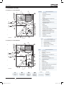 342
342
-
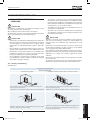 343
343
-
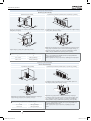 344
344
-
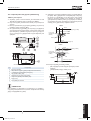 345
345
-
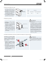 346
346
-
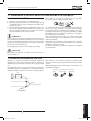 347
347
-
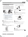 348
348
-
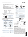 349
349
-
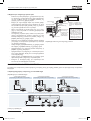 350
350
-
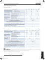 351
351
-
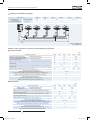 352
352
-
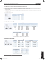 353
353
-
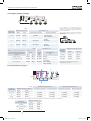 354
354
-
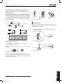 355
355
-
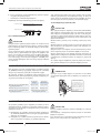 356
356
-
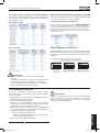 357
357
-
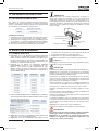 358
358
-
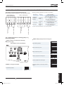 359
359
-
 360
360
-
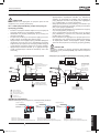 361
361
-
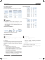 362
362
-
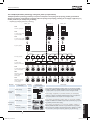 363
363
-
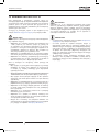 364
364
-
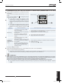 365
365
-
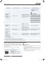 366
366
-
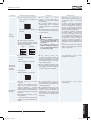 367
367
-
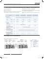 368
368
-
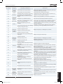 369
369
-
 370
370
-
 371
371
-
 372
372


Hitachi RAS-10HNCE Istruzioni per l'uso
- Categoria
- Condizionatori d'aria a sistema split
- Tipo
- Istruzioni per l'uso
in altre lingue
- English: Hitachi RAS-10HNCE Operating instructions
- français: Hitachi RAS-10HNCE Mode d'emploi
- español: Hitachi RAS-10HNCE Instrucciones de operación
- Deutsch: Hitachi RAS-10HNCE Bedienungsanleitung
- Nederlands: Hitachi RAS-10HNCE Handleiding
- português: Hitachi RAS-10HNCE Instruções de operação
- dansk: Hitachi RAS-10HNCE Betjeningsvejledning
- svenska: Hitachi RAS-10HNCE Bruksanvisningar
Documenti correlati
-
Hitachi HRNM/FSN(2)(M)(E) Istruzioni per l'uso
-
-
-
-
-
-
-
-
Hitachi DHWT300E-2.5H1E Istruzioni per l'uso
-
Altri documenti
-
McQuay 5ACV 55 CR Guida d'installazione
-
Acson IM-5ACV3-0505-ACSON Guida d'installazione
-
-
Haier 1U24GE6ERA Guida d'installazione
-
Haier 1U12BS1ERA Guida d'installazione
-
-
-
Castorama SCJA2519 Guida d'installazione
-
Panasonic CZANC3 Istruzioni per l'uso
-
Fujitsu AOYG90LRLA Guida d'installazione