
KCM Kondensatormodule
KCM Capacitor Modules
KCM Modulo Condensatore
KCM Módulos de Condensadores
Usable with AKD, S300, S400, S600, S700 (400/480V, max. 24A)
DEUTSCH
Betriebsanleitung
ENGLISH
Instruction Manual
ITALIANO
Manuale di Istruzioni
ESPAÑOL
Manual de instrucciones
Ausgabe/Edition/Edizione/Edition 01/2014
Datei/File/File KCM_deis.***
Bewahren Sie das Handbuch als Produktbestandteil während
der Lebensdauer des Produktes auf. Geben Sie das Handbuch
an nachfolgende Benutzer oder Besitzer des Produktes weiter.
Keep the manual as a product component during the life span of
the product. Pass the manual to future users / owners of the
product.
Conservare il manuale per l’intera durata del prodotto. In caso di
cambio di proprietà il manuale deve essere fornito al nuovo uti
-
lizzatore quale parte integrante del prodotto.
Conserve el manual durante toda la vida útil del producto.
Entregue el manual a posteriores usuarios o propietarios del
producto.

Record of Document Revisions
Revision Remarks
04 / 2013 First multilingual edition
05 / 2013 Correction Weight KCM-P
06 / 2013 Discharging time changed from 30s to 70s
01 / 2014 Switch-on sequence updated, safe voltage 40V->60V, KCM-P ready signal, X4-RS422
Technische Änderungen, die der Verbesserung der Geräte dienen, vorbehalten!
Originalbetriebsanleitung, gedruckt in der BRD
Alle Rechte vorbehalten. Kein Teil des Werkes darf in irgendeiner Form (Fotokopie, Mikrofilm oder in einem
anderen Verfahren) ohne schriftliche Genehmigung der Firma Kollmorgen reproduziert oder unter Verwen-
dung elektronischer Systeme verarbeitet, vervielfältigt oder verbreitet werden.
Technical changes to improve the performance of the equipment may be made without prior notice!
Translation of the original manual, printed in the Federal Republic of Germany
All rights reserved. No part of this work may be reproduced in any form (by photocopying, microfilm or any
other method) or stored, processed, copied or distributed by electronic means without the written permission
of Kollmorgen.
Il produttore si riserva la facoltà di apportare modifiche tecniche volte al miglioramento degli appa-
recchi
Traduzione del manuale originale, stampato nella Repubblica federale tedesca
Tutti i diritti riservati. Nessuna parte di questo documento può essere rielaborata, riprodotta in qualsiasi
forma (fotocopia, microfilm o altro processo) o diffusa mediante l'uso di sistemi elettronici senza l'approva-
zione scritta della ditta Kollmorgen o rielaborata, riprodotta o diffusa mediante l’uso di sistemi elettronici.
Reservado el derecho de introducir modificaciones técnicas para la mejora de los equipos
Traducción del manual original, impreso en la RFA
Reservados todos los derechos. Prohibida la reproducción total o parcial de la presente obra por cualquier
medio (fotocopia, microfilm u otros), así como su procesamiento, reproducción y divulgación por medio de
sistemas electrónicos, sin expresa autorización escrita de la empresa Kollmorgen.
TOC Dr uck
1 KCM Kondensatormodule
1.1 Allgemeines ......................3
1.2 Sicherheit ........................3
1.3 Technische Daten .................5
1.4 Mechanische Installation ............6
1.5 Elektrische Installation ..............7
1.6 Inbetriebnahme ..................10
1.7 KCM Module entladen .............10
2 KCM Capacitor Modules
2.1 General ........................11
2.2 Safety ..........................11
2.3 Technical Data ...................13
2.4 Mechanical Installation.............14
2.5 Electrical Installation ..............15
2.6 Setup ..........................18
2.7 Discharging KCM modules .........18
3 KCM Moduli Condensatore
3.1 Informazioni generali ..............19
3.2 Sicurezza .......................19
3.3 Dati tecnici ......................21
3.4 Installazzione meccanica...........22
3.5 Installazione elettrica ..............23
3.6 Messa in funzione ................26
3.7 Scaricare i moduli KCM ............26
4 KCM Módulos de Condensadores
4.1 Generalidades ...................27
4.2 Seguridad.......................27
4.3 Datos técnicos ...................29
4.4 Instalación mecánica ..............30
4.5 Instalación eléctrica ...............31
4.6 Puesta en funcionamiento ..........34
4.7 Descarga de los módulos KCM ......34
5 Approvals
5.1 CE ............................35
5.2 UL Markings.....................35
Inhaltsverzeichnis, Table of Content, Sommario, Sumario

1 KCM Kondensatormodule
1.1 Allgemeines
Die KCM Module (KOLLMORGEN Capacitor Module) nehmen Energie auf, die der Motor
im generatorischen Betrieb erzeugt. Normalerweise wird diese Energie über Bremswider-
stände in Verlustleistung umgesetzt. Die KCM Module speisen die gespeicherte Energie
in den Zwischenkreis zurück, wenn sie benötigt wird.
KCM-S Spart Energie: Die beim generatorischen Bremsen im Kondensatormodul ge-
speicherte Energie steht für den nächsten Beschleunigungsfall zur Verfügung.
Die Einsatzspannung des Moduls wird automatisch während der ersten Last-
zyklen ermittelt.
KCM-P Power trotz Netzausfall: Bei Ausfall der Leistungsversorgung stellt das Modul
dem Servoverstärker die gespeicherte Energie für ein gesteuertes Stillsetzen
des Antriebs zur Verfügung (nur Leistungsspannung, 24V separat puffern).
KCM-E Erweiterungsmodul für beide Einsatzzwecke. Erweiterungsmodule sind in zwei
Kapazitätsklassen verfügbar.
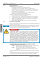
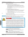
1.2 Sicherheit
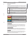
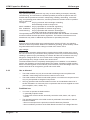
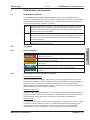
1.2.1 Verwendete Symbole
Symbol Bedeutung
Weist auf eine gefährliche Situation hin, die, *wenn sie nicht vermieden
wird, zum Tode oder zu schweren, irreversiblen Verletzungen führen wird
.
Weist auf eine gefährliche Situation hin, die, wenn sie nicht vermieden wird,
zum Tode oder zu schweren, irreversiblen Verletzungen führen kann
.
Weist auf eine gefährliche Situation hin, die, wenn sie nicht vermieden wird,
zu leichten Verletzungen führen kann
.
Dies ist kein Sicherheits-Symbol. Es weist auf eine Situation hin, die, wenn
sie nicht vermieden wird, zu Beschädigung von Sachen führen kann
.
Dies ist kein Sicherheits-Symbol. Dieses Symbol weist auf wichtige Informa-
tionen hin
.
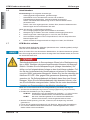
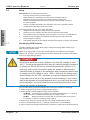
1.2.2 Das sollten Sie beachten
Dokumentation lesen
Lesen Sie vor der Montage und Inbetriebnahme die vorliegende Dokumentation. Fal-
sches Handhaben der KCM Module kann zu Personen- oder Sachschäden führen. Der
Betreiber muss daher sicherstellen, dass alle mit Arbeiten an KCM Modulen betrauten
Personen das Handbuch gelesen und verstanden haben und dass die Sicherheitshin-
weise in diesem Handbuch beachtet werden.
Technische Daten beachten
Halten Sie die technischen Daten und die Angaben zu den Anschlussbedingungen
(Typenschild und Dokumentation) ein. Wenn zulässige Spannungswerte oder Stromwerte
überschritten werden, können die Module z.B. durch Überhitzung geschädigt werden.
Heiße Oberfläche
Die Module können im Betrieb bis zu 80°C heiß werden. Bei Berührung besteht die
Gefahr leichter Verbrennungen. Beachten Sie die zulässige Einbaulage (senkrecht, Erd
-
anschlüsse unten) und achten Sie auf ausreichend Abstand (rechts/links > 20mm,
unten/oben>100mm) zu benachbarten Baugruppen.
Betriebsanleitung Deutsch - 3
Kollmorgen 01/2014 KCM Kondensatormodule
DEUTSCH

Fachpersonal erforderlich
Nur qualifiziertes Fachpersonal darf Arbeiten wie Transport, Montage, Inbetriebnahme
und Instandhaltung ausführen. Qualifiziertes Fachpersonal sind Personen, die mit Trans
-
port, Aufstellung, Montage, Inbetriebnahme und Betrieb von Leistungselektronik vertraut
sind und über die ihrer Tätigkeit entsprechenden Mindestqualifikationen verfügen:
Transport: nur durch Personal mit Kenntnissen in der Behandlung
elektrostatisch gefährdeter Bauelemente
Mech. Installation: nur durch Fachleute mit maschinenbautechnischer Ausbildung
Elektr. Installation: nur durch Fachleute mit elektrotechnischer Ausbildung
Inbetriebnahme: nur durch Fachleute mit weitreichenden Kenntnissen in
den Bereichen Elektrotechnik / Antriebstechnik
Das Fachpersonal muss ebenfalls IEC 60364 / IEC 60664 und nationale Unfallverhü-
tungsvorschriften kennen und beachten. Aus der Risikobeurteilung des Maschinenher-
stellers leiten sich eventuell zusätzliche Anforderungen an das Fachpersonal ab.
Erdung
Stellen Sie die ordnungsgemäße Erdung der KCM Module mit der PE-Schiene im Schalt-
schrank als Bezugspotential sicher. Ohne niederohmige Erdung ist keine personelle
Sicherheit gewährleistet und es besteht Lebensgefahr durch elektrischen Schlag.
Hohe Spannungen
Halten Sie während des Betriebs der KCM Module den Schaltschrank geschlossen. Zie-
hen Sie keine Stecker während des Betriebs, in ungünstigen Fällen können Lichtbögen
entstehen und Personen und Kontakte schädigen. Zwischenkreisanschlüsse können über
eine Stunde nach Abschalten der Netzspannung gefährliche Spannung führen (Selbst-
entladezeit). Lebensgefahr durch elektrischen Schlag.
Vor Installation oder Deinstallation müssen KCM Module komplett entladen werden. Füh-
ren Sie die Entladung wie im Kapitel "Module entladen" beschrieben durch.
Prüfen Sie vor Arbeitsbeginn an den Leistungsanschlüssen der Module die Spannung an
den Anschlussklemmen gegen Erde und gegeneinander auf Spannungsfreiheit.
1.2.3 Bestimmungsgemäße Verwendung
— Die KCM Module dürfen nur an Kollmorgen Servoverstärkern mit 400/480V Nenn-
spannung und maximal 24A Nennstrom angeschlossen werden.
— Die KCM Module werden als Bauteile in elektrische Anlagen oder Maschinen einge-
baut und dürfen nur als integrierte Bauteile in Betrieb genommen werden.
— Die Konformität der KCM Module zu den in der EG-Konformitätserklärung genann-
ten Normen garantieren wir nur, wenn von uns gelieferte Komponenten (Servover-
stärker, Motor, Leitungen usw.) verwendet werden.
1.2.4 Nicht bestimmungsgemäße Verwendung
— Der Betrieb der KCM Module ist verboten
- in explosionsgefährdeten Bereichen,
- in Umgebungen mit ätzenden und/oder elektrisch leitenden Säuren, Laugen, Ölen,
Dämpfen, Stäuben.
— Der bestimmungsgemäße Betrieb der KCM Module ist untersagt, wenn die Maschi-
ne, in die sie eingebaut wurden,
- nicht den Bestimmungen der EG Maschinenrichtlinie entspricht,
- nicht die Bestimmungen der EMV- und Niederspannungs-Richtlinien erfüllt.
Deutsch - 4 Betriebsanleitung
KCM Kondensatormodule 01/2014 Kollmorgen
DEUTSCH

1.2.5 Handhabung
1.2.5.1 Transportieren
—
Klimaklasse 2K3 nach EN61800-2, IEC 60721-3-2
—
Temperatur: -25..+70°C, max. 20K/Stunde schwankend
Luftfeuchtigkeit: relative Feuchte 5% ... 95% nicht kondensierend
— Überprüfen Sie bei beschädigter Verpackung das Modul auf sichtbare Schäden.
Informieren Sie den Transporteur und gegebenenfalls den Hersteller.
1.2.5.2 Lagern
— Klimaklasse 1K4 nach EN61800-2, IEC 60721-3-2
— Lagertemperatur -25...+55°C, max. 20K/Stunde schwankend
Luftfeuchtigkeit relative Feuchte 5% ... 95% nicht kondensierend
— Nur in der Originalverpackung des Herstellers, max. Stapelhöhe: 10 Kartons
— Lagerdauer > 1 Jahr: Kondensatoren müssen vor der Inbetriebnahme neu formiert
werden. Lösen Sie alle elektrischen Anschlüsse. Speisen Sie das KCM etwa
1Stunde/Lagerjahr mit max. 200V DC an den Klemmen +/- DC.
1.2.5.3 Warten / Reinigen
— Wartung und Reinigung nur von qualifiziertem Personal
— Gehäusereinigung mit Isopropanol o.ä., nicht tauchen oder absprühen
1.2.5.4 Deinstallieren
1. Gerät sicher entladen (siehe Kapitel "KCM Module Entladen" auf S.10)
2. Entladehilfsmittel (Steckbrücke, Verbindungskabel) gesteckt lassen
3. Spannungsfreiheit DC+/DC-, DC+/PE, DC-/PE prüfen
4. Verdrahtung entfernen, KCM Modul demontieren
1.2.5.5 Reparieren / Entsorgen
Reparaturen darf nur der Hersteller durchführen, Öffnen der Geräte bedeutet Verlust der
Gewährleistung. Gemäß der WEEE-2002/96/EG-Richtlinien nehmen wir Altgeräte und
Zubehör zur fachgerechten Entsorgung zurück, sofern die Transportkosten vom Absen-
der übernommen werden. Senden Sie die Geräte zur Reparatur oder Entsorgung an:
KOLLMORGEN Europe GmbH, Pempelfurtstr. 1, D-40880 Ratingen
1.3 Technische Daten
Typ DIM KCM-S200 KCM-P200 KCM-E200 KCM-E400
Speicherkapazität
Ws 1600 2000 2000 4000
Nenn-Anschlussspannung
V= max 850
Spitzen-Anschlussspannung
V= max 950 (30s in 6min)
Leistung
kW 18 18 18 18
Schutzart
IP20
Einsatzspannung
V= ermittelt 470 - -
Anschlussquerschnitt
mm² max. 6
Maße (HxBxT)
mm 300 x 100 x 201
Gewicht
kg 6,9 6,9 4,1 6,2
zul. Umgebungstemperatur
°C 0 ... 40
Betriebsanleitung Deutsch - 5
Kollmorgen 01/2014 KCM Kondensatormodule
DEUTSCH

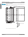
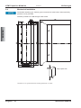
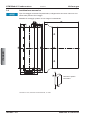
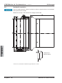
1.4 Mechanische Installation
Zulässige Montageart: Senkrecht, Erdanschlüsse unten. Andere Montagelagen sind nicht
zulässig.
Montagematerial: vier Innensechskant-Schrauben M6.
Maße in mm, Freimaßtoleranzen nach DIN7168, T1 mittel
Deutsch - 6 Betriebsanleitung
KCM Kondensatormodule 01/2014 Kollmorgen
DEUTSCH
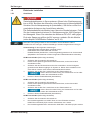
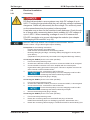
Freiräume einhalten!

1.5 Elektrische Installation
1.5.1 Anschluss
Zwischenkreisklemmen in Servosystemen führen hohe Gleichspannung
bis zu 900V. Berühren der Klemmen unter Spannung ist lebensgefährlich.
Schalten Sie die Netzspannung ab (freischalten). Sie dürfen nur bei frei-
geschalteter Anlage an den Anschlüssen arbeiten.
Die Selbstentladezeit der Module kann über eine Stunde betragen. Prüfen
Sie den Ladezustand mit einem für Gleichspannung bis 1000V geeigne-
ten Messgerät. Wenn Sie zwischen den Klemmen DC+/DC- oder gegen
Erde eine Spannung größer als 60V messen, entladen Sie die Module
(siehe Kapitel "KCM Module Entladen" auf S.10).
Maximale Leitungslänge zwischen Servoverstärker und KCM Modul: 500mm.
Verdrillen Sie die Leitungen. Größere Kabellängen erfordern abgeschirmte Leitungen.
Voraussetzung für die folgenden Anweisungen:
- Ordnungsgemäß freigeschaltete, geerdete Anlage.
- KCM Module sind im Schaltschrank montiert.
- Entladehilfsmittel (Steckbrücke, Verbindungskabel) gesteckt wie im Lieferzustand
(Kapazitäten sind dauerhaft mit dem integrierten Entladewiderstand verbunden).
KCM-S anschließen (Reihenfolge einhalten!)
1. Schließen Sie als erstes die Schutzerde an.
2. Prüfen Sie die Spannungsfreiheit des Zwischenkreises, an den Sie KCM-S
anschließen wollen.
3. Schließen Sie den BR Anschluss an den Servoverstärker mit den häufigsten
generatorischen Bremsvorgängen im System an. Dieser Servoverstärker muss
einen aktiven internen oder externen Bremswiderstand besitzen.
4. Schließen Sie die DC+/DC- Anschlüsse an den Zwischenkreis an.
Achten Sie auf korrekte Polung, bei Vertauschen von DC+/DC-
werden die KCM Module zerstört.
5. Entfernen Sie die Entladehilfsmittel (Steckbrücke).
KCM-P anschließen (Reihenfolge einhalten!)
1. Schließen Sie als erstes die Schutzerde an.
2. Prüfen Sie die Spannungsfreiheit des Zwischenkreises, an den Sie KCM-P
anschließen wollen.
3. Schließen Sie die DC+/DC- Anschlüsse an den Zwischenkreis an.
Achten Sie auf korrekte Polung, bei Vertauschen von DC+/DC-
werden die KCM Module zerstört.
4. Entfernen Sie die Entladehilfsmittel (Steckbrücke).
KCM-E anschließen (Reihenfolge einhalten!)
1. Schließen Sie als erstes die Schutzerde an.
2. Das Verbindungskabel vom KCM-E lösen und zum Entladen zwischen
KCM-E/X3 und KCM-S(-P)/X1 stecken. Mindestens 140 s warten.
3. Das Verbindungskabel lösen und zwischen KCM-E/X1 und KCM-S(-P)/X1 stecken.
Betriebsanleitung Deutsch - 7
Kollmorgen 01/2014 KCM Kondensatormodule
DEUTSCH

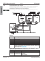
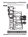
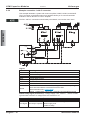
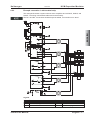
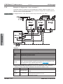
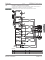
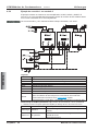
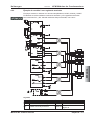
1.5.2 Anschlussbeispiel 1 mit Y-Stecker
Das Beispiel zeigt ein System mit Servoverstärker, KCM-P, KCM-S und KCM-E. Der
Y-Stecker am Kollmorgen Servoverstärker ermöglicht den Anschluss von zwei
KCM-Modulen am Zwischenkreis eines Servoverstärkers.
Die Verbindungen DC+ und DC- sollten immer verdrillt geführt werden (max. 6mm²).
Legende:
Kürzel Bedeutung
DC+ Gleichstrom Zwischenkreis positiv
DC- Gleichstrom Zwischenkreis negativ
BR Brems-Chopper
RBint Interner Bremswiderstand
RBintern Chopper Eingang für internen Bremswiderstand
RBext Externer Bremswiderstand
PE Schutzerde
RS422
Serielle Schnittstelle X4 zum Anschluss an PC, Gegenstecker liegt bei,
beliebige Terminalsoftware zur Kommunikation verwenden. Weitere Infor-
mation finden Sie im Produkt WIKI
.
Einstellung: 115200 Baud, 8 Data Bits, 1 Stop Bit, No Parity&Flow Control
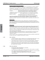
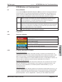
KCM-P Ready Signal (Klemmen 4,6): Schaltspannung +24V, Widerstand 1...100 kW
gegen Masse. Typische Abfallzeiten auf unter 5V kleiner 4 ms.
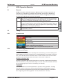
Klemme 6 KCM-P Status Mögliche Ursachen
High-Signal Betriebsbereit. Ladevorgang beendet, Spannung im Toleranzbereich.
Low-Signal Nicht betriebsbereit
- KCM-P ist noch im Lademodus
- Netzausfall.
- KCM-P ist defekt.
Deutsch - 8 Betriebsanleitung
KCM Kondensatormodule 01/2014 Kollmorgen
DEUTSCH

1.5.3 Anschlussbeispiel 2 mit Klemmleiste
Das Beispiel zeigt ein System zwei Servoverstärkern, KCM-P, KCM-S und KCM-E. Die
Verdrahtung erfolgt über verdrillte Leitungen und über eine Klemmleiste.
Die Verbindungen DC+ und DC- sollten immer verdrillt geführt werden (max. 6mm²)
Legende:
Kürzel Bedeutung Kürzel Bedeutung
DC+ Gleichstrom Zwischenkreis positiv RBext Externer Bremswiderstand
DC- Gleichstrom Zwischenkreis negativ BR Brems-Chopper
PE Schutzerde RS422 X4 Details siehe Seite 8
Betriebsanleitung Deutsch - 9
Kollmorgen 01/2014 KCM Kondensatormodule
DEUTSCH

1.6 Inbetriebnahme
Voraussetzung für die folgenden Anweisungen:
- Ordnungsgemäß freigeschaltete, geerdete Anlage.
- KCM Module sind im Schaltschrank montiert und verdrahtet.
- Entladehilfsmittel (Steckbrücke, Verbindungskabel) sind entfernt.
- KCM-P: Die Netzausfall-Überwachung muss im Servoverstärker korrekt
parametriert sein.
- KCM-S: Last muss angekoppelt sein, die dazu führt, dass beim Abbremsen der
Bremschopper des Servoverstärkers aktiv wird.
Gehen Sie wie folgt vor (Reihenfolge einhalten!):
1. 24V Versorgungsspannung des Servoverstärkers einschalten.
2. Netzspannung einschalten, wenn der Verstärker-Startvorgang beendet ist.
3. KCM-P beginnt den Ladevorgang bei ca. 470V DC, die LED blinkt.
4. Servoverstärker freigeben und ein Fahrprofil fahren, das zum Ansprechen des
Bremschoppers führt.
5. KCM-S ermittelt die Chopperschwelle und beginnt zu laden, die LED blinkt.
1.7 KCM Module entladen
Die jedem Modul beiliegenden Hilfsmittel (Steckbrücke bzw. Verbindungskabel) ermögli-
chen das sichere Entladen der Module.
Wenn die Lade-LED in der Oberseite der Module blinkt, sind die Kondensatoren geladen.
Die LED ermöglicht jedoch keine sichere Aussage über den Entladezustand, da sie nicht
auf Ausfall überwacht wird.
Zwischenkreisklemmen in Servosystemen führen hohe Gleichspannung
bis zu 900V. Berühren der spannungsführenden Klemmen ist lebensge-
fährlich. Schalten Sie die Netzspannung ab (Anlage freischalten). Sie
dürfen nur bei freigeschalteter Anlage an den Anschlüssen arbeiten. Prü-
fen Sie den Ladezustand der Kondensatoren mit einem für Gleichspan-
nung bis 1000V geeigneten Messgerät. Warten Sie, bis die zwischen den
Klemmen DC+/DC- oder gegen Erde gemessene Spannung unter 60V
gesunken ist. Die Selbstentladezeit der Module kann über eine Stunde
betragen. Wenn Sie die Selbstentladezeit nicht abwarten können, müs-
sen Sie die Module zwangsentladen. Halten Sie das unten beschrieben
Vorgehen zur Zwangsentladung der Module unbedingt ein.
Gehen Sie zu Ihrer Sicherheit bei der Zwangsentladung der Module wie folgt vor:
1. Schalten Sie die Netzspannung und 24V Versorgungsspannung ab (freischalten).
2. Entladen Sie die Module (ca. 70s pro Modul):
KCM-S/-P: Steckbrücke in die Schraubklemmen (schwarz-1 <=> grau-2) an der
Unterseite der Module stecken, Steckbrücke stecken lassen.
KCM-E: Mit einem Verbindungskabel an der Oberseite des Moduls die
Stecker X2/X3 brücken, Verbindungskabel stecken lassen.
3. Messen Sie die Spannung +DC/-DC , warten Sie, bis die Spannung unter 60V
gesunken ist.
4. Führen Sie die geplante Aufgabe durch (z.B. Reinigen, Warten oder Deinstallieren).
5. Vor erneuter Inbetriebnahme Steckbrücke bzw. Verbindungskabel lösen und die
Geräte wieder korrekt anschließen.
Deutsch - 10 Betriebsanleitung
KCM Kondensatormodule 01/2014 Kollmorgen
DEUTSCH

2 KCM Capacitor Modules
2.1 General
KCM modules (KOLLMORGEN Capacitor Modules) absorb energy generated by the
motor when it is operating in generator mode. Normally, this energy is dissipated as
waste via brake resistors. KCM modules, however, feed the energy they have stored
back into the DC Bus link as and when it is required.
KCM-S Saves energy: The energy stored in the capacitor module during regenerative
braking is available the next time acceleration happens. The module’s incepti-
on voltage is calculated automatically during the first load cycles.
KCM-P Power in spite of power failure: If the power supply fails, the module provides
the servo amplifier with the stored energy that is required to bring the drive to a
standstill in a controlled manner (this only applies to the power supply voltage;
battery-back the 24 V supply separately).
KCM-E Expansion module for both applications. Expansion modules are available in
two capacitance classes.
2.2 Safety
2.2.1 Symbols used
Symbol Indication
Indicates a hazardous situation which, if not avoided, will result in death or
serious injury
.
Indicates a hazardous situation which, if not avoided, could result in death
or serious injury
.
Indicates a hazardous situation which, if not avoided, could result in minor
or moderate injury
.
This is not a safety symbol. This symbol indicates situations which, if not
avoided, could result in property damage
.
This is not a safety symbol. This symbol indicates important notes.
2.2.2 You should pay attention to this
Read the documentation!
Read this documentation prior to assembly and commissioning. Incorrect handling of the
KCM modules may lead to personal injury or material damage. The operator must, there-
fore, ensure that all persons entrusted to work on KCM modules have read and unders-
tood the manual and that the safety information in the manual is observed.
Observe the technical data!
Observe the technical data and the information on connection requirements (rating plate
and documentation). If the permissible voltage or current values are exceeded, the modu-
les may be damaged (as a result of overheating, for example).
Hot surfaces!
The KCM modules can reach temperatures of up to 80°C during operation. Touching
them can result in minor burns. Observe the permissible mounting position (vertical,
ground connections at the bottom) and ensure that a sufficient distance is maintained
from neighboring assemblies (right/left > 20 mm, above/below > 100 mm).
Instruction Manual English - 11
Kollmorgen 01/2014 KCM Capacitor Modules
ENGLISH

Specialist staff required
Only qualified specialist personnel may carry out work relating to transport, assembly,
commissioning, and maintenance. Qualified specialist personnel are persons who are
familiar with the processes involved in transporting, installing, assembling, commissio
-
ning, and operating power electronics, and who possess the relevant minimum qualifica
-
tions for their field:
Transport: Only by personnel with knowledge of handling
electrostatically-sensitive components
Mech. installation: Only by specialists in mechanical engineering
Elec. installation: Only by specialists in electrical engineering
Commissioning: Only by specialists with extensive knowledge in
the fields of electrical engineering/drive technology
The specialist personnel must also observe and be familiar with IEC 60364 / IEC 60664,
as well as national accident prevention regulations. The machine manufacturer’s risk
assessment may result in additional requirements for specialist personnel.
Earthing
Ensure that the KCM modules are grounded properly with the PE rail in the switching
cabinet as reference potential. Without low-resistance grounding, personal safety cannot
be guaranteed and there will be a danger of death from electric shock.
High voltages
Ensure that the switching cabinet remains closed while the KCM modules are in opera-
tion. Do not remove any connectors during operation as this may cause electrical arcing,
resulting in personal injury and damage to contacts. DC Bus link connections can carry
dangerous voltage levels over an hour after the line voltage has been switched off
(self-discharge time). Danger of death from electric shock.
The KCM modules must be completely discharged prior to installation or uninstallation.
Perform the discharge process as described in the chapter “Discharging KCM modules”.
Before commencing work on the modules’ power terminals, check the voltage at the con-
nection terminals is de-energized to ground and to each other.
2.2.3 Use as directed
— The KCM modules may only be connected to Kollmorgen servo amplifiers with
400/480 V rated voltage and a maximum rated current of 24 A.
— The KCM modules are built into electrical systems or machines as components and
may only be operated as integrated components.
— We only guarantee that the KCM modules conform to the standards referred to in
the EC Declaration of Conformity if the components that we have supplied are used
(servo amplifier, motor, cables, etc.).
2.2.4 Prohibited use
— You must not operate the KCM modules
- in potentially explosive areas
- in areas with corrosive and/or electrically conductive acids, bases, oils, vapors,
or dusts.
— The intended operation of the KCM module is prohibited if the machine in which it
has been installed
- does not correspond to the provisions of the EC Machinery Directive
- does not fulfill the provisions of the EMC Directive and the Low Voltage Directive.
English - 12 Instruction Manual
KCM Capacitor Modules 01/2014 Kollmorgen
ENGLISH

2.2.5 Handling
2.2.5.1 Transport
—
Climatic class 2K3 according to EN61800-2, IEC 60721-3-2
—
Temperature: -25 to +70°C, max. 20 K/hour variable
Humidity: Relative humidity 5% to 95% non-condensing
— If the packaging is damaged, check the module for visible damage. Inform the cou-
rier and, if necessary, the manufacturer.
2.2.5.2 Storage
— Climatic class 1K4 according to EN61800-2, IEC 60721-3-2
— Storage temperature: -25 to +55?, max. 20 K/hour variable
Humidity: Relative humidity 5% to 95% non-condensing
— Only in the manufacturer’s original packaging, max. stacking height: 10 boxes
— Storage period > 1 year: Prior to commissioning, capacitors must be re-formed. Dis-
connect all electrical connections. Supply the KCM with max. 200 V DC at the
+/- DC terminals for approx. 1 hour per year of storage.
2.2.5.3 Maintenance/Cleaning
— Maintenance and cleaning may only be performed by qualified personnel
— Clean the housing with isopropyl alcohol or similar; do not immerse or spray
2.2.5.4 Uninstallation
1. Discharge the device safely (see chapter “Discharging KCM modules” on p.18)
2. Leave discharge aids (plug-in bridge, connecting cables) plugged in
3. Check that DC+/DC-, DC+/PE, and DC-/PE are de-energized
4. Remove wiring, dismantle KCM module
2.2.5.5 Repairs/Disposal
Repairs must only be performed by the manufacturer; opening the devices will invalidate
the warranty. In accordance with the WEEE-2002/96/EC directives, we take old devices
and accessories back to dispose of them professionally, provided that the transport costs
are borne by the sender. Please send devices for repair or disposal to:
KOLLMORGEN Europe GmbH, Pempelfurtstr. 1, D-40880 Ratingen
2.3 Technical Data
Type DIM KCM-S200 KCM-P200 KCM-E200 KCM-E400
Storage capacity
Ws 1600 2000 2000 4000
Rated supply voltage
V= max. 850
Peak supply voltage
V= max. 950 (for 30s in 6min)
Power
kW 18 18 18 18
Protection class
IP20
Inception voltage
V= evaluated 470 - -
Wiring cross section
mm² 6 max.
Dimensions (HxWxD)
mm 300 x 100 x 201
Weight
kg 6.9 6.9 4.1 6.2
Permissible ambient temp.
°C 0 ... 40
Instruction Manual English - 13
Kollmorgen 01/2014 KCM Capacitor Modules
ENGLISH

2.4 Mechanical Installation
Permissible assembly type: Vertical, ground connections at the bottom. Other assembly
positions are not permitted.
Assembly material: Four M6 hexagon head screws.
Dimensions in mm, general tolerances according to DIN7168, T1 middle
English - 14 Instruction Manual
KCM Capacitor Modules 01/2014 Kollmorgen
ENGLISH
Keep space free!

2.5 Electrical Installation
2.5.1 Connecting
DC Bus link terminals in servo systems carry high DC voltage of up to
900 V. Touching the terminals while they are carrying voltage is extremely
dangerous. Switch off (disconnect) the line voltage. You must only work
on the connections when the system is disconnected.
It can take over an hour for the modules to self-discharge. Check the sta-
te of charge with a measuring device that is suitable for a DC voltage of
up to 1,000 V. When measuring a voltage of over 60 V between the
DC+/DC- terminals or to ground, discharge the modules (see chapter
“Discharging KCM modules” on p.18).
Maximum cable length between servo amplifier and KCM module: 500 mm.
Twist the cables. Longer cable lengths require shielding.
Prerequisite for the following instructions:
- Properly disconnected, grounded system
- KCM modules are assembled in the switching cabinet
- Discharge aids (plug-in bridge, connecting cables) are plugged in as they were
upon delivery.
(Capacitances are permanently connected to the integrated discharge resistor.)
Connecting the KCM-S (do this in the order specified)
1. First connect the protective ground.
2. Check that the DC Bus to which you wish to connect the KCM-S is de-energized.
3. Connect the BR connection to the servo amplifier with the most frequent
regenerative braking processes in the system. This servo amplifier must have an
active internal or external brake resistor.
4. Connect the DC+/DC- connections to the DC Bus link.
Ensure that the polarity is correct; swapping round DC+/DC-
will damage the KCM modules beyond repair.
5. Remove the discharge aids (plug-in bridge).
Connecting the KCM-P (do this in the order specified)
1. First connect the protective ground.
2. Check that the DC Bus to which you wish to connect the KCM-P, is de-energized.
3. Connect the DC+/DC- connections to the DC Bus link.
Ensure that the polarity is correct; swapping round DC+/DC-
will damage the KCM modules beyond repair.
4. Remove the discharge aids (plug-in bridge).
Connecting the KCM-E (do this in the order specified)
1. First connect the protective ground.
2. Detach the connecting cable from the KCM-E and plug it in between
KCM-E/X3 and KCM-S(-P)/X1 for discharging purposes. Wait at least 140 s.
3. Detach the connecting cable and plug it in between KCM-E/X1 and KCM-S(-P)/X1.
Instruction Manual English - 15
Kollmorgen 01/2014 KCM Capacitor Modules
ENGLISH

2.5.2 Example connection 1 with Y connector
This example illustrates a system with a servo amplifier, KCM-P, KCM-S, and KCM-E.
The Y connector on the Kollmorgen servo amplifier allows you to connect two KCM
modules to the DC Bus link of a servo amplifier.
The DC+ and DC- connections should always be twisted, cross section max. 6mm².
Legend:
Abbreviation Meaning
DC+ DC Bus link positive
DC- DC Bus link negativ
BR Brake Chopper
RBint Internal brake resistor
RBintern Chopper input for internal brake resistor
RBext External brake resistor
PE Protection earth
RS422
Serial Interface X4 to connect a PC, mating connector in the package,
use a terminal software to transmit/receive the data.
More information see Product WIKI
.
Setting: 115200 Baud, 8 Data Bits, 1 Stop Bit, No Parity&Flow Control
KCM-P Ready Signal (terminal 4,6) : Voltage supply +24V, resistor 1...100 kW to GND.
Typical switch-off time to a voltage below 5V: less than 4 ms.
Terminal 6 KCM-P Status Possible causes
High-Signal Ready to operate Capacitors loaded, voltage inside tolerance
Low-Signal Not ready to operate
- KCM-P is still in mode "loading"
- Mains supply fault.
- KCM-P is faulty.
English - 16 Instruction Manual
KCM Capacitor Modules 01/2014 Kollmorgen
ENGLISH

2.5.3 Example connection 1 with terminal strip
This example illustrates a system with two servo amplifiers and a KCM-P, KCM-S, and
KCM-E. The wiring uses twisted cables and a terminal strip.
The DC+ and DC- connections should always be twisted, cross section max. 6mm².
Legend:
Abbr. Meaning Abbr. Meaning
DC+ DC Bus link positive BR Brake Chopper
DC- DC Bus link negative RBext External brake resistor
PE Protective Earth RS422 X4 Details see page 16
Instruction Manual English - 17
Kollmorgen 01/2014 KCM Capacitor Modules
ENGLISH

2.6 Setup
Prerequisite for the following instructions:
- Properly disconnected, grounded system
- KCM modules are assembled and wired in the switching cabinet
- Discharge aids (plug-in bridge, connecting cables) are removed
- KCM-P: The power failure monitoring must be parameterized correctly in
the servo amplifier
- KCM-S: The load that leads to the activation of the servo amplifier’s brake
chopper during braking must be connected.
Proceed as follows (do this in the order specified):
1. Switch on the 24V supply voltage of the servo amplifier.
2. Switch on the line voltage, after the 24V boot process has finished.
3. The KCM-P begins the charging process at approx. 470 V DC; the LED flashes.
4. Enable the servo amplifier and operate the driving profile that causes the
brake chopper to respond
5. The KCM-S determines the chopper threshold and begins to charge; LED flashes.
2.7 Discharging KCM modules
The aids supplied with each module (plug-in bridge/connecting cables) allow you to
discharge the modules safely.
When the charging LED on top of the modules flashes, the capacitors are charged.
Please note, however, that the LED does not safely indicate the real state of discharge,
as it is not supervised for failures.
DC Bus link terminals in servo systems carry high DC voltage of up to
900 V. Touching the terminals while they are carrying voltage is extreme-
ly dangerous. Switch off the line voltage (disconnect the system). You
must only work on the connections when the system is disconnected.
Check the state of charge of the capacitors with a measuring device that
is suitable for a DC voltage of up to 1,000 V. Wait until the voltage mea-
sured between the DC+/DC- terminals or to ground dropped below 60 V.
It can take over an hour for the modules to self-discharge. If you cannot
wait for the duration of the self-discharge time, you must force the modu-
les to discharge. You must follow the procedure described below when
forcing the modules to discharge.
For your own safety, proceed as follows when forcing the modules to discharge:
1. Switch off (disconnect) the line voltage and 24V supply.
2. Discharge the modules (approximately 70 s per module):
KCM-S/-P: Insert the plug-in bridge in the screw terminals (black-1 <=> gray-2)
on the base of the modules. Leave the plug-in bridge in place.
KCM-E: Bridge the X2/X3 connector with a connecting cable on the top of
the module. Leave the connecting cable in place.
3. Measure the +DC/-DC voltage and wait until voltage dropped below 60 V.
4. Perform the scheduled task (e.g., cleaning, maintenance, or uninstallation).
5. Remove the plug-in bridge respectively the connection cable before recommissioning.
English - 18 Instruction Manual
KCM Capacitor Modules 01/2014 Kollmorgen
ENGLISH

3 KCM Moduli Condensatore
3.1 Informazioni generali
I moduli KCM (KOLLMORGEN Capacitor Module) assorbono energia generata dal
motore in modalità generatore. Di regola questa energia viene convertita in potenza dissi-
pata attraverso resistenze di frenatura esterne. I moduli KCM alimentano l’energia accu-
mulata al circuito DC-link, quando è necessario.
KCM-S Sistema di risparmio energetico: L’energia accumulata nel modulo condensa-
tore durante la frenata rigenerativa è a disposizione per l’accelerazione suc-
cessiva. La tensione d’esercizio del modulo viene rilevata automaticamente
durante i primi cicli di caricamento.
KCM-P Potenza anche in caso di caduta di alimentazione: In assenza di alimentazio-
ne di potenza il modulo fornisce al servoamplificatore l’energia accumulata per
un arresto controllato dell’azionamento (solo tensione di alimentazione, 24 V
accumulo separato).
KCM-E Espansione del modulo per entrambi gli utilizzi. I moduli di espansione sono
disponibili in due livelli di capacità.
3.2 Sicurezza
3.2.1 Simboli utilizzati
Symbolo Significato
Segnala una situazione di pericolo che, se non evitata, comporta la morte o
lesioni gravi e permanenti
.
Segnala una situazione di pericolo che, se non evitata, può comportare la
morte o lesioni gravi e permanenti
.
Segnala una situazione di pericolo che, se non evitata, può comportare in-
fortuni leggeri
.
Questo non è un simbolo di sicurezza, ma serve a segnala una situazione
di pericolo che, se non evitata, può comportare danni materiali
.
Questo non è un simbolo di sicurezza, ma serve a segnalare informazioni
importanti
.
3.2.2 Si dovrebbe prestare attenzione a questo
Leggere la documentazione
Prima di procedere al montaggio e alla messa in funzione leggere attentamente la pre-
sente documentazione. L’errata manipolazione dei moduli KCM può comportare danni a
persone o a cose. L’operatore è quindi tenuto ad assicurarsi che tutto il personale
addetto a lavori sui moduli KCM abbia letto e compreso il manuale e che le indicazioni di
sicurezza riportate nel manuale siano rispettate.
Rispettare i dati tecnici
Rispettare i dati tecnici e le indicazioni sulle condizioni di collegamento (targhetta di omo-
logazione e documentazione). Se si superano i valori di tensione e di corrente ammessi, i
moduli possono essere danneggiati, ad esempio a causa del surriscaldamento.
Superfici calde
In corso di funzionamento i moduli possono raggiungere temperature fino a 80°C. In caso
di contatto sussiste il pericolo di ustioni lievi. Rispettare la posizione di montaggio con
-
sentita (perpendicolare, collegamenti a terra sotto) e assicurare la debita distanza
(destra/sinistra > 20 mm, sotto/sopra >100 mm) rispetto ai componenti adiacenti.
Manuale di Istruzioni Italiano - 19
Kollmorgen 01/2014 KCM Moduli Condensatore
ITALIANO

Interventi riservati al personale qualificato
I lavori di trasporto, montaggio, messa in funzione e manutenzione si possono affidare
esclusivamente a personale tecnico qualificato, che abbia familiarità con il trasporto,
l’installazione, il montaggio, la messa in funzione e il funzionamento di componenti elet
-
tronici e che disponga di opportune qualifiche di base per lo svolgimento di tali attività.
Trasporto: solo da parte di personale con conoscenze in materia di
elementi costruttivi a rischio di scariche elettrostatiche
Installazione meccanica: solo da parte di personale con una formazione meccanica
Installazione elettrica: solo da parte di tecnici con formazione elettrotecnica
Messa in funzione: solo da parte di tecnici con ampie conoscenze nei
nei settori dell’elettrotecnica e dei sistemi di azionamento
Il personale qualificato deve inoltre conoscere e rispettare le norme IEC 60364 / IEC
60664 nonché le disposizioni antinfortunistiche nazionali. L’analisi dei rischi del
produttore potrebbe comportare la necessità di ulteriori requisiti per il personale tecnico.
Messa a terra
Assicurare la regolare messa a terra dei moduli KCM con la bandella PE all’interno
dell’armadio di distribuzione come potenziale di riferimento. Senza una messa a terra a
bassa impedenza non viene garantita la sicurezza personale e sussiste pericolo di morte
per scosse elettriche.
Alta tensione
Si raccomanda inoltre di tenere chiuso il quadro elettrico ad armadio durante il funziona-
mento dei moduli KCM. Non staccare nessun connettore durante il funzionamento: in
casi sfavorevoli possono venire a crearsi archi voltaici con conseguenti danni a carico di
persone e contatti. I collegamenti del circuito DC-link possono condurre tensione perico-
losa oltre un’ora dopo la disinserzione della tensione di rete (tempo di autoscarica). Peri-
colo di morte per scosse elettriche.
Prima dell’installazione o della disinstallazione i moduli KCM devono essere completa-
mente scarichi. Effettuare la scarica secondo le indicazioni riportate nel capitolo
“Scaricare i moduli”.
Prima di iniziare i lavori sui collegamenti di potenza dei moduli controllare la tensione dei
morsetti verso terra e l’assenza di tensione tra i morsetti..
3.2.3 Uso conforme
— I moduli KCM devono essere collegati solo a servoamplificatori Kollmorgen con una
tensione nominale di 400/480V e una corrente nominale massima di 24A.
— I motori KCM vengono montati come componenti su impianti elettrici o macchine e
possono essere messi in funzione solo come componenti integrati dell’impianto.
— Garantiamo la conformità dei moduli KCM alle norme menzionate nella dichiarazio-
ne di conformità CE solo se vengono utilizzati componenti originali (servoamplifica-
tori, motore, cavi, e così via).
3.2.4 Uso non conforme
— Il funzionamento dei moduli KCM non è consentito
- in ambienti a rischio di esplosione,
- in ambienti con oli, vapori, polveri, soluzioni alcaline, acidi corrosivi e/o conduttivi.
—
L’uso conforme dei moduli KCM non è possibile, se la macchina in cui sono montati,
- non rispetta i requisiti imposti dalla Direttiva macchine CE,
- non soddisfa i requisiti imposti dalla Direttiva in materia di compatibilità
elettromagnetica.
Italiano - 20 Manuale di Istruzioni
KCM Moduli Condensatore 01/2014 Kollmorgen
ITALIANO
La pagina si sta caricando...
La pagina si sta caricando...
La pagina si sta caricando...
La pagina si sta caricando...
La pagina si sta caricando...
La pagina si sta caricando...
La pagina si sta caricando...
La pagina si sta caricando...
La pagina si sta caricando...
La pagina si sta caricando...
La pagina si sta caricando...
La pagina si sta caricando...
La pagina si sta caricando...
La pagina si sta caricando...
La pagina si sta caricando...
La pagina si sta caricando...
-
 1
1
-
 2
2
-
 3
3
-
 4
4
-
 5
5
-
 6
6
-
 7
7
-
 8
8
-
 9
9
-
 10
10
-
 11
11
-
 12
12
-
 13
13
-
 14
14
-
 15
15
-
 16
16
-
 17
17
-
 18
18
-
 19
19
-
 20
20
-
 21
21
-
 22
22
-
 23
23
-
 24
24
-
 25
25
-
 26
26
-
 27
27
-
 28
28
-
 29
29
-
 30
30
-
 31
31
-
 32
32
-
 33
33
-
 34
34
-
 35
35
-
 36
36


Kollmorgen KCM-S200 Manuale utente
- Tipo
- Manuale utente
- Questo manuale è adatto anche per
in altre lingue
- English: Kollmorgen KCM-S200 User manual
- español: Kollmorgen KCM-S200 Manual de usuario
- Deutsch: Kollmorgen KCM-S200 Benutzerhandbuch