Lince 1897BOBBY-AM/UE Istruzioni per l'uso
- Categoria
- Illuminazione di comodità
- Tipo
- Istruzioni per l'uso
Questo manuale è adatto anche per

IT
EN
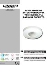
RILEVATORE DA ESTERNO
UNIVERSALE TRIPLA TECNOLOGIA
A BASSO ASSORBIMENTO CON
ANTIMASCHERAMENTO
Manuale di installazione, uso e manutenzione
Installation, operation and maintenance manual
LOW ABSORPTION UNIVERSAL TRIPLE
TECHNOLOGY OUTDOOR DETECOR
WITH ANTI-MASKING
MADE IN ITALY
ART. / ITEM:
1896BOBBY-AM/U
1897BOBBY-AM/UE
1929-BOBBY-UE
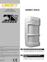
BOBBY UNIVERSALE
CON ANTIMASKING
UNIVERSAL BOBBY
WITH ANTIMASKING
La dichiarazione CE del presente articolo
è reperibile su sito www.lince.net.
The CE declaration of this item is available
on www.lince.net website.

2
LINCE ITALIA S.p.A.
- Istruzioni originali -
1. INTRODUZIONE ................................................................................................2
1.1 CARATTERISTICHE GENERALI ........................................................... 2
1.2 CARATTERISTICHE TECNICHE ........................................................... 3
1.3 CONTENUTO DELLA CONFEZIONE .................................................... 3
1.4 IDENTIFICAZIONE DELLE PARTI ......................................................... 4
1.4.1 Cover PIR superiore .................................................................... 4
2. FUNZIONI SPECIALI ........................................................................................5
2.1 FUNZIONE WIN ..................................................................................... 5
2.2 ANTIMASCHERAMENTO ...................................................................... 5
2.3 FUNZIONE TEST ................................................................................... 5
2.4 INIBIZIONE ............................................................................................ 5
3. INSTALLAZIONE...............................................................................................6
3.1 AVVERTENZE GENERALI ..................................................................... 6
3.2 FISSAGGIO SU MURO .......................................................................... 6
3.3 FISSAGGIO SU PALO ........................................................................... 7
3.4 CABLAGGIO DEL RILEVATORE ...........................................................8
3.5 CHIUSURA DEL RILEVATORE .............................................................. 8
3.6 ESEMPI DI MONTAGGIO ...................................................................... 9
3.7 REGOLAZIONE DELLA DISTANZA DI RILEVAZIONE ........................ 10
3.8 GRAFICO DI COPERTURA (VISTA IN PIANTA).................................. 12
3.9 CONFIGURAZIONE DEL RILEVATORE ..............................................12
4. ESEMPIO DI RILEVAMENTO .........................................................................13
5. ACCESSORI DISPONIBILI ............................................................................. 14
5.1 STAFFA ................................................................................................ 14
5.2 COVER PARAPIOGGIA ....................................................................... 14
5.3 KIT RISCALDATORE ...........................................................................14
5.4 STAFFA ................................................................................................ 15
6. RICERCA DEI GUASTI E/O MALFUNZIONAMENTI .................................... 15
7. MANUTENZIONE E VERIFICHE PERIODICHE ............................................. 15
8. SMALTIMENTO E ROTTAMAZIONE .............................................................. 16
INDICE
Le informazioni riportate in questo manuale sono state compilate con
cura, tuttavia LINCE ITALIA S.p.A. non può essere ritenuta responsabile
per eventuali errori e/o omissioni. LINCE ITALIA S.p.A. si riserva il diritto
di apportare in ogni momento e senza preavviso, miglioramenti e/o
modiche ai prodotti descritti nel presente manuale. Consultare il sito
www.lince.net per le condizioni di assistenza e garanzia. LINCE ITALIA
S.p.A. pone particolare attenzione al rispetto dell’ambiente. Tutti i prodotti
ed i processi produttivi sono progettati con criteri di eco-compatibilità.
Il presente articolo è stato prodotto in Italia.
• L’azienda ha un sistema di gestione della qualità certicato
secondo la norma ISO 9001:2008 (n° 4796 - A)
• L’azienda ha un sistema di gestione ambientale certicato
secondo la norma ISO 14001:2004 (n° 4796 - E)
• L’azienda ha un sistema di gestione della salute e sicurezza sul
lavorocerticatosecondolanormaISO45001:2018(n°4796-I)
The information in this manual has been issued with care, but LINCE
ITALIA S.p.A. will not be responsible for any errors or omissions. LINCE
ITALIA S.p.A. reserves the right to improve or modify the products
described in this manual at any time and without advance notice.Terms
and conditions regarding assistance and the product warranty can be
found at LINCE ITALIA’s website www.lince.net. LINCE ITALIA S.p.A.
makes it a priority to respect the environment. All products and production
processes are designed to be eco-friendly and sustainable.
This product has been Made in Italy.
• The company has a certied system of quality management
according to ISO 9001:2008 (n° 4796 - A) standard.
• The company has a certied system of environmental
management according to ISO 9001:2004 (n° 4796 - E) standard.
• The company has a certied system of health and work
securitymanagementaccordingtoISO45001:2018(n°4796-I)
standard.
-Translationoftheoriginalinstructions(originalinstructionsinItalian)-
1. INTRODUCTION ...............................................................................................2
1.1 GENERAL FEATURES .......................................................................... 2
1.2 TECHNICAL FEATURES ....................................................................... 3
1.3 PACKAGING CONTENTS ..................................................................... 3
1.4 PARTS IDENTIFICATION....................................................................... 4
1.4.1 Upper PIR cover .......................................................................... 4
2. SPECIAL FUNCTIONS......................................................................................5
2.1 WIN FUNCTION ..................................................................................... 5
2.2 ANTI-MASKING...................................................................................... 5
2.3 TEST FUNCTION ..................................................................................5
2.4 INHIBITION MODE................................................................................. 5
2. INSTALLATION ................................................................................................. 6
3.1 GENERAL PRECAUTIONS ................................................................... 6
3.2 WALL FIXING ......................................................................................... 6
3.3 POLE FIXING ......................................................................................... 7
3.4 DETECTOR WIRING .............................................................................8
3.5 DETECTOR CLOSING ........................................................................... 8
3.6 FIXING EXAMPLES ............................................................................... 9
3.7 DETECTION RANGE ADJUSTMENT .................................................. 10
3.8 COVERED AREA PATTERN (PLAN VIEW) ......................................... 12
3.9 DETECTOR SET-UP ............................................................................ 12
4. DETECTING EXAMPLE ..................................................................................13
5. AVAILABLE ACCESSORIES .......................................................................... 14
5.1 BRACKET .............................................................................................14
5.2 RAIN COVER ....................................................................................... 14
5.3 HEATER KIT ......................................................................................... 14
5.4 BRACKET .............................................................................................15
6. TROUBLE SHOOTING ...................................................................................15
7. MAINTENANCE AND PERIODIC CHECKS ................................................... 15
8. DISPOSAL AND SCRAPPING ........................................................................ 16
CONTENTS
1. INTRODUZIONE
Il rilevatore da esterno BOBBY UNIVERSALE è composto da
due sensori passivi dual PIR e da una microonda a 24 GHz.
L’elettronica è stata progettata per garantire le massime
prestazioni in ambiente esterno e a temperature rigide. I
fasci sono orientabili e permettono di ottenere una copertura
orizzontale distribuita su 170°. Oltre alle funzioni di rilevazione
il rilevatore è dotato della funzione di ANTIMASKING ad
infrarossi attivi. Tale funzione è stata implementata per rendere
il rilevatore inattaccabile da quanti potrebbero avere accesso
al sito dove il rilevatore è installato durante il periodo in cui il
sistema risulta disinserito; segnala ogni tentativo di impedire il
suo funzionamento bloccando (mascherando) il suo campo di
rilevazione che avviene tramite 2 PIR ed una Microonda a 24
GHz. L’ altezza di installazione è compresa tra 1 e 1,2 m con
area di una copertura di 15 m, 12 m nella versione con MW, ed
apertura di 85°. La regolazione micrometrica del PIR inferiore
permette di adattare la portata di rilevazione da 3 a 15 m.
Realizzato completamente in policarbonato resistente ad urti e
raggi UV con lente di Fresnel made in USA e ltri solari made in
Japan. I 4 LED di segnalazione di cui 2 verdi per i PIR, 1 giallo
per la microonda ed 1 rosso per l’allarme permettono di sapere
se una tecnologia sta rilevando o meno. la funzione Pet Immunity
è disponibile se utilizzato in triplo AND. Supporto di ssaggio in
acciaio inox (fornito) e staffe da palo disponibili su richiesta. Offre
anche la possibilità di alimentazione supplementare esterna WIN
a 12 V che lo rende equiparabile ad un rilevatore lare.
1. INTRODUCTION
The outdoor universal BOBBY UNIVERSALE detector consists of
two dual PIR sensors and a 24 GHz microwave. The electronics
are designed to provide maximum performance in outdoor
and extreme conditions. The beams are adjustable and allow
for a horizontal coverage of 170°. In addition to the detection
functions, the detector is equipped with the active infrared ANTI-
MASKING function.
This function has been implemented to make the detector
immune to those who may have access to the site where the
detector is installed during the period when the system is turned
off; it indicates any attempt to prevent its operation by blocking
(masking) its detection range by means of 2 PIRs and a 24 GHz
Microwave. The installation height is between 1 and 1.2 m with
a coverage area of 15 m and opening of 85°. The micrometric
control of the lower PIR allows to adjust the detection range from
3 to 15 m, 12 m in the MW version . Made entirely of impact
resistant polycarbonate and UV rays with Fresnel lens made in
USA and sun lters made in Japan.
The 4 LEDs of which 2 green for the PIRs, 1 yellow for the
microwave and 1 red for the alarm signal allow you to know
whether a technology is detecting or not. The Pet Immunity
function is available if used in Triple AND. Stainless steel xing
bracket (supplied) and pole brackets available on request.
It also offers the feature of an additional 12 V WIN external power
supply that makes it comparable to a wired detector.

3
LINCE ITALIA S.p.A.
1.2 CARATTERISTICHE TECNICHE
1896BOBBY-AM/U 1897BOBBY-AM/UE 1929-BOBBY-UE
Alimentazione / Power supply 2.5÷9 Vdc
Consumo / Current consumption 10 µA stand-by
Frequenza microonda / Microwavefrequncy Banda K NO
Funzione antimanomissione /Antitamperfunction Microswitch
Antimascheramento / Antimasking IR attivi NO
Funzione WIN / WINfunction 10 ÷ 15 Vdc (WIN) NO
Portata di rilevazione / Detection range 3 m ÷ 12 m 3 m ÷ 15 m
Ampiezza orizzontale del fascio / Horizontal beam detection 85°
Escursione orizzontale / Horizontal detection excursion ±45°.
LED di segnalazione /Signal LEDs 4 3
Grado di protezione contenitore
Enclosuredegreeofprotection IP 45
Classe ambientale / Environmentalclassication Classe IV (EN 50131-4) / Class IV (EN 50131-4)
Grado di sicurezza / Security grading Grado 3 (EN 50131-2-4)
Grade 3 (EN 50131-2-4)
Grado 3 (EN 50131-2-2)
Grade 3 (EN 50131-2-2)
Contenitore / Casing Policarbonato resistente UV / UV resistant polycarbonate
Temperatura di esercizio / Operating temperature -25 °C ÷ +60 °C
Dimensioni esterne (LxPxA mm)
External dimensions
(WxDxH mm) 81x98x189
Peso (g) / Weight (g) 820 (compreso staffe) / 820 (including brackets)
1.2 TECHNICAL FEATURES
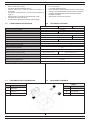
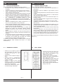
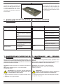
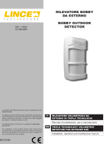
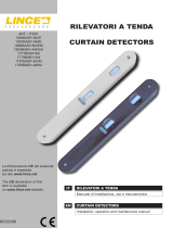
1.3 CONTENUTO DELLA CONFEZIONE
C
A
B
1.3 PACKAGING CONTENTS
Tabella 1
Part. Identicazione
ARilevatore
BKit di ssaggio al muro
e kit cavi
CIstruzioni
Table 1
Ref. Identication
ADetector.
BKit for wall mounting
and cable kit
CIstructions
Fig. 1
1.1 CARATTERISTICHE GENERALI
• Basso consumo di corrente;
• Circuito di rilevazione batteria scarica;
• Sensore DUAL PIR a lente di Fresnel più sensore a
microonda;
• Contenitore in policarbonato e lenti di Fresnel resistenti ai
raggi UV;
• Design estetico e meccanico particolarmente curato;
• Conforme alle norme EN 50131;
• Funzione WIN: alimentazione tramite rete principale.
1.1 GENERAL FEATURES
• Low consumption;
• Low battery detecting circuit;
• DUAL PIR sensor with Fresnel lens and microwave sensor;
• Casing in polycarbonate and Fresnel lenses UV resistant;
• Carefully developed aesthetic and mechanical design;
• EN 50131compliant;
• WIN function: power from the mains.

4
LINCE ITALIA S.p.A.
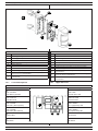
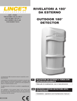
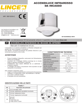
Fig. 2
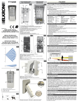
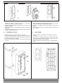
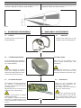
1.4 IDENTIFICAZIONE DELLE PARTI 1.4 PARTS IDENTIFICATION
Tabella 2
Part. Identicazione
AViti di ssaggio del supporto rilevatore sulla staffa.
BVite di ssaggio del coperchio con lente.
CCoperchio con lente di Fresnel.
DPomello con vite metrica di regolazione PIR basso.
ESupporto elettronica.
FMicrointerruttore con funzione antistrappo (solo se ssato con la vite A).
GStaffa in acciaio inox.
HStaffe per ssaggio a palo (non fornite art.: 001805/00092AA).
IVite metrica M4 x 6 inox per ssaggio staffe ad “U” (q.tà 4) contenute
nel kit accessorio art. 001805/00092AA.
LViti metriche M4 x 10 inox (q.tà 4) contenute nel kit accessorio art.
001805/00092AA.
B
Table 2
Ref. Identication
ABracket screws.
BCover mounting screw.
CCover with Fresnel lens.
DAdjusting knob for lower PIR (PIR2).
EElectronic holder.
FAnti Tamper function micro switch (only if A screw is mounted).
GStainless steel support.
HStainless steel pole mounting brackets (not supplied item:
001805/00092AA).
IStainless Steel metric screw M4 x 6 for “U” brackets xing (4 pcs)
enclosed into kit item 001805/00092AA.
LStainless Steel metric screw M4 x 10 (4 pcs) enclosed into kit item
001805/00092AA.
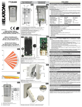
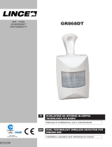
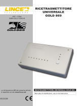
1.4.1 Cover PIR superiore
Tabella 3 / Table 3
Descrizione Description
A
LED 1 ROSSO
LED allarme generale
A
LED 1 RED
General alarm LED
B
LED 2 GIALLO
LED Microonda
B
LED 2 YELLOW
Microwave LED
C
LED 3 VERDE
LED PIR 1 (PIR superiore)
C
LED 3 GREEN
PIR 1 (upper PIR) LED
D
LED 4 VERDE
LED PIR 2 (PIR inferiore)
D
LED 4 GREEN
PIR 2 (lower PIR) LED
E
Trimmer MW
E
MW Trimmer
F
DIP-Switch
F
DIP-Switch
1.4.1 Upper PIR cover
D B
A C
F
E
Fig. 3
L
A
D
G
H
E
F
I
L
C
B

5
LINCE ITALIA S.p.A.
2. FUNZIONI SPECIALI 2. SPECIAL FUNCTION
2.1 FUNZIONE WIN
Utilizzando la funzione WIN (Wired Interface Network) è possibi-
le alimentare il dispositivo attraverso l’alimentazione principale,
mantenendo la Microonda sempre accesa ed avendo dunque le
stesse prestazioni di un rilevatore lare. Quando il rilevatore è
alimentato con una tensione maggiore di 10 V, viene automati-
camente attivata la funzione WIN. In modalità WIN i LED sono
sempre attivi e la microonda sempre accesa. Quando la tensio-
ne di alimentazione del rilevatore scende sotto 10 V, il rilevatore
ritorna in funzionamento in modalità batteria, dove i LED sono
spenti e la microonda subordinata alla rilevazione di uno dei PIR.
Il cavo per connettere la scheda all’alimentazione WIN è forni-
to in dotazione, collegandolo prestando attenzione al verso del
connettore.
2.1 WIN FUNCTION
Using the WIN function (Wired Interface Network) it is possible
to power the devices from the mains, keeping the Microwave
always ON and therefore offering the same performance as a
wired detector. When the detector is powered at a voltage higher
than 10 V, the WIN function automatically comes ON. In WIN
mode both LEDs and microwave are always on. When the de-
tector feed voltage drops below 10 V, the detector goes back to
battery-operation mode, where the LEDs are off and the micro-
wave is subordinate to the detection by one of the PIRs.
The cable to connect the board to the WIN power supply is sup-
plied, connecting it by paying attention to the connector side.
2.3 FUNZIONE TEST
Il rilevatore entra nella modalità di test appena viene collegato il
cavo di collegamento a 12 vie. In questa condizione i LED sono
attivi. Dopo circa quattro minuti il rilevatore esce automaticamente
dalla modalità TEST e i LED si spengono (se alimentato tramite
batteria). Per provare l’area di copertura, è importante che il
rilevatore sia chiuso. Una volta effettuate le prove di rilevazione,
il rilevatore è pronto per il funzionamento. Al termine della fase
di test il funzionamento del rilevatore potrà essere vericato in
accordo con il sistema radio al quale è collegato. Per uscire dalla
modalità di test, il dispositivo non deve rilevare per almeno 4
minuti. V
2.4 INIBIZIONE
Nel funzionamento normale con alimentazione a batteria il
rilevatore attiva, automaticamente la funzione INIBIZIONE per
ottimizzare il consumo della batteria; questo comporta che
se l’ambiente è frequentato, il rilevatore rimarrà inibito per 30
secondi o 3 minuti (a seconda della protezione selezionato).
Afnché il rilevatore esca dallo stato di inibizione, durante il tempo
di inibizione impostato, non deve avvenire alcuna rilevazione.
2.3 TEST FUNCTION
The detector goes into test mode as soon as the 12-way
connection cable is connected. The LEDs are active in this
condition. After approximately four minutes the detector
automatically exits TEST mode and the LEDs switch off (if
powered with battery). To test the coverage area, the detector
needs to be closed. When the detection test have been carried
out, the detector is ready to work. At the end of the test phase,
detector operation can be checked based on the radio system to
which it is connected to. To exit test mode, the device must not
detect for four minutes at least.
2.4 INHIBITION MODE
During normal operation in battery mode, the detector auto-
matically goes into INHIBITION MODE function to optimize the
battery consumption; this means that if there is activity in the
range, the detector will be inhibited for 30 seconds or 3 minutes
(depending on protection selected). No detection is required for
the detector to exit from the inhibition mode, during the setted
inhibition time.
Per far ripartire il test è necessario aprire e chiudere il
coperchio oppure spegnere il rilevatore e accenderlo
nuovamente dopo 3 minuti. Appena chiuso il coperchio,
il rilevatore effettua una taratura delle tecnologie, la procedura
viene segnalata tramite lampeggio alternato di tutti i LED.
To restart the test you need to open and close the lid or
turn off the detector, and turn it on again after 3 minutes.
As soon as the cover is closed, the detector performs a
calibration of the technologies, the procedure is signaled by al-
ternating ashing of all the LEDs
2.2 ANTIMASCHERAMENTO
I rilevatori 1896BOBBY-AM/U e 1897BOBBY-AM/UE sono dota-
ti di antimascheramento a infrarossi attivi per la protezione dei
sensori piroelettrici, che genera un segnale di manomissione
entro 3 minuti. Per abilitare il funzionamento corretto della rile-
vazione di mascheramento (Anti-masking), è necessario con-
sentire al rilevatore di studiare ed analizzare automaticamente
le condizioni ambientali dell’area che deve proteggere. Questa
procedura è obbligatoria per assicurare la corretta segnalazione
della condizione di mascheramento. La procedura da seguire è
la seguente:
• Dopo aver effettuato tutte le prove di portata necessarie per
il funzionamento desiderato, aprire il coperchio e abilitare
con il DIP 7 e 8 la funzione anti-mascheramento;
• chiudere il coperchio e Tenersi fuori dall’area di copertura
del rilevatore per circa 4 minuti afnché, durante questo
periodo, non venga rilevata nessuna presenza e vericare
2.2 ANTI-MASKING
The detectors 1896BOBBY-AM/U e 1897BOBBY-AM/UE are
equipped with an active IR anti-masking function to protect the
pyroelectric sensors. It emits a tampering signal within 3 minu-
tes.
To enable the correct operation of the masking detection system
(Anti-masking), allow the detector to study and analyse the envi-
ronmental conditions of the area to be protected. This procedu-
re is mandatory to ensure the correct signalling of the masking
condition.
Follow the procedure below:
• After performing all the required tests for the desired
operation, open the cover and enable DIP 7 and 8 for anti-
masking function;
• close the lid and keep out of the detector coverage area for
about 4 minutes in order to not detecte any presence and
pay attention that there are no objects within 1 m.

6
LINCE ITALIA S.p.A.
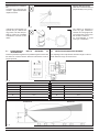
3.2 FISSAGGIO SU MURO
3. INSTALLAZIONE
3.1 AVVERTENZE GENERALI
Prima dell'installazione vericare le seguenti condizioni:
• la parete non deve presentare avvallamenti o sporgenze
eccessive;
• installare il rilevatore su superci rigide prive di vibrazioni;
• evitare il posizionamento del rilevatore vicino a fonti di
calore o alla luce diretta del sole;
• evitare la riessione dell’energia elettromagnetica su ampie
superci quali, ad esempio, specchi, pareti metalliche, etc.;
• evitare di puntare il rilevatore su lampade uorescenti o
comunque di porlo nelle immediate vicinanze delle stesse.
• per i collegamenti è consigliabile utilizzare un cavo
schermato e, preferibilmente, un cavo per ogni rilevatore.
• separare i cavi dell’impianto di allarme da quelli della rete
elettrica.
• l’altezza di installazione deve essere compresa tra i 1 m
min. ed 1,2 m max (terreno non in pendenza).
• evitare di puntare il rilevatore verso oggetti in movimento o,
se ciò risultasse inevitabile, prestare la massima cura nelle
regolazioni al ne di evitare falsi allarmi;
• evitare siti dove possano esserci piante a ridosso del
rilevatore e/o piante che crescendo possano arrivare
all’altezza del rilevatore stesso creando così fastidiosi falsi
allarmi;
• apporre sempre il coperchio con lente di Fresnel prima di
effettuare le prove di copertura, senza lente il rilevatore non
funziona;
• se nell’area di copertura c’è la possibilità che vi sia presenza
di animali di medie dimensioni si consiglia di installare
il rilevatore ad una altezza tale da evitare che il fascio
superiore rilevi la presenza dell’animale stesso.
Il rilevatore può essere installato in ambiente esterno (secondo
quanto prescritto dalla normativa EN 50131-1 in classe
ambientale IV).
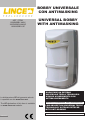
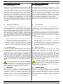
Fig. 4
• Svitare la vite e togliere il coperchio
con lente;svitare le sette viti di
ssaggio del rilevatore al fondo
contenitore;
• ssare il fondo contenitore stagno a
muro,
• forare il muro in corrispondenza
dei quattro fori presenti sul fondo.
Inserire i 4 tasselli;
• poggiare il fondo al muro quindi
avvitare le quattro viti nei tasselli
facendo attenzione a non danneggiare
il pretaglio per antistrappo;
• usare il foro inferiore per ssare il
contenitore stagno alla parete.
• Unscrew the screw and remove the
cover with lens; unscrew the seven
xing screws of the detector to the
waterproof rear casing;
• x the hermetic casing on the wall;
• perforate the wall in corrispondence
of the holes on the casing;
• insert wallplugs into the holes and
screw up the case with the 4 screws.
Pay attention to not damage anti-
tamper switch support knockout;
• use the lower hole to x the hermetic
casing on the wall.
3.2 WALL FIXING
3. INSTALLATION
3.1 GENERAL PRECAUTIONS
Before starting the installation, make sure that:
• the wall does not have any pronounced depressions or
protrusions;
• the detector must be installed on rigid surfaces, free of
vibrations;
• avoid positioning the detectors near heat sources or in direct
sunlight;
• avoid electromagnetic energy reection on wide surfaces
such as mirrors, metal walls, etc.;
• avoid xing the detector in front of uorescent lamps or in
proximity of them;
• connections shielded cable is suggested and one cable per
detector is preferred;
• separate the alarm system cables from the mains cables;
• installation height must be between 1 m and 1.20 m (not
tilted ground);
• avoid pointing the detector towards moving objects or, if not
possible, please pay special attention to sensor settings in
order to avoid false alarms;
• to avoid false alarms, do not install the detector behind big
trees/bushes;
• be sure to install the cover with Fresnel lens before the
detector testing. Without cover, the detector doesn’t work;
• if medium-sized animals might enter the coverage area, we
recommend installing the detector at a height that allows you
to prevent the upper beam from detecting their presence.
The detector can be installed outdoors (according to the Class IV
EN 50131-1).

7
LINCE ITALIA S.p.A.
• Cablare, secondo le proprie necessità il trasmettitore
(consultare il relativo manuale istruzioni),
• inserirlo e ssarlo all’interno dell’apposito vano presente nel
contenitore stagno,
• inserire la guarnizione o-ring nella sede presente sul supporto
elettronica,
• accoppiare il rilevatore con il fondo stagno quindi avvitare le
sette viti metriche in dotazione.
• Wiring as needed the transmitter (see its instruction manual),
• insert the transmitter into the hermetic casing,
• insert the o-ring gasket into its seat located on the electronic
holder,
• couple the detector and the hermetic casing then screw the
seven screws.
Fig. 5
3.3 FISSAGGIO SU PALO 3.3 POLE FIXING
• Fissare la staffa ad “L” dietro il fondo con una vite;
• posizionare le due staffe ad “U” attorno al palo quindi bloccarle
avvitando le quattro viti interne (due per staffa) e le quattro viti
esterne rimanenti (due per staffa);
• usare il foro superiore per ssare il contenitore alla staffa ad
“L” (g. 6).
• Fix the “L” shape bracket behind the hermetic casing with
one screw;
• position the “U” shaped bracket around the pole, block them
with the four inner screws (two for each bracket) and the four
external screws (two for each bracket;
• use the upper hole to x the case to the “L” shaped bracket
(g. 6).
Fig. 6

8
LINCE ITALIA S.p.A.
3.5 CHIUSURA DEL RILEVATORE
• Dopo aver effettuato le regolazioni meccaniche del PIR
inferiore e della sensibilità dei PIR, chiudere il rilevatore
applicando il coperchio con lente di Fresnel dall’alto verso il
basso come in gura.
• Fissare avvitando la vite metrica in acciaio inox (rif. H, v.
3.5 DETECTOR CLOSING
• After adjusting lower PIRmechanical features and both PIRs
sensitivity from topo to bottom, as shown in the gure below
close the detector with the front cover with Fresnel lens.
• Hook it up to the electronic holder side ant screw up the
metric screw (ref. H, see g. 4).
Fig. 7
Non può essere denito un cablaggio
univoco in quanto, per rendere il
rilevatore universale è stato lasciato
all’installatore il compito di collegare
i cavi in base alle necessità e alle
caratteristiche del trasmettitore
utilizzato. Vericare se il trasmettitore
gestisce ingressi NA oppure NC
(riferirsi al manuale del trasmettitore
che si intende installare). Il rilevatore
è dotato di un apposito cavo a 12
li da utilizzare per realizzare i
collegamenti. Dopo aver effettuato i
collegamenti al modulo radio, collegare il cavo con la scheda
elettronica, servendosi degli appositi connettori, come mostrato
in gura. Nell’immagine a lato è riportato il dettaglio della scheda
dove viene evidenziata la posizione del connettore. Nella tabella
seguente sono illustrate le corrispondenze tra i colori dei li del
cavo e le uscite del rilevatore.
Tabella 4
DESCRIZIONE COLORE
ALIMENTAZIONE BATTERIA ROSSO
MASSA NERO
ALLARME NC MARRONE
ALLARME C ROSA
ALLARME NA ARANCIO
ANTIMASK NC (usato solo per 1896 e 1897) GIALLO
ANTIMASK C (usato solo per 1896 e 1897) VERDE
ANTIMASK NA (usato solo per 1896 e 1897) BLU
TAMPER NA (∗) VIOLA
TAMPER C GRIGIO
TAMPER NC (∗) BIANCO
ALIMENTAZIONE FILARE (WIN) AZZURRO
NOTA:
• per garantire il controllo dello stato di carica della batteria, si
consiglia di alimentare il rilevatore con la stessa batteria del
trasmettitore e quindi non utilizzarne una dedicata;
• (∗) la congurazione riportata in tabella si intende a coperchio
chiuso.
3.4 CABLAGGIO DEL RILEVATORE 3.4 DETECTOR WIRING
To make the detector universal it is
not possible to dene a single wiring
set-up, accordingly, the installation
technician is responsible for
connecting the cables based on the
demands and characteristics of the
selected transmitter. Check whether
the transmitter controls NO or NC
inputs (refer to the manual of the
transmitter that you intend to install).
The detector is equipped with a 12-
wire cable, which is used to set up the
connections. When the connections
to the radio module are set up, connect the cable to the
electronic board using the relative connectors, as shown in the
gure. The picture on the side shows the details of the board
where the position of the connector is highlighted. The table
below illustrates how to match up the cable wire colours and the
detector outputs.
Table 4
DESCRIPTION
COLOUR
BATTERY SUPPLY RED
EARTH BLACK
NC ALARM BROWN
C ALARM PINK
NO ALARM ORANGE
NC ANTIMASK (used only for 1896 and 1897) YELLOW
C ANTIMASK (used only for 1896 and 1897) GREEN
NO ANTIMASK (used only for 1896 and 1897) BLUE
NO TAMPER (∗) PURPLE
C TAMPER GREY
NC TAMPER (∗) WHITE
WIRE POWER SUPPLY (WIN) LIGHT BLUE
NOTE:
• in order to ensure control of the battery charge status, it is
advisable to feed the detector with the same battery as the
transmitter and therefore not to use one dedicated;
• (∗) the conguration shown in the table is intended with the
cover closed.

9
LINCE ITALIA S.p.A.
Fig. 8
Fig. 9
Fig. 10
MONTAGGIO CORRETTO
Montare il rilevatore in posizione verticale e perpendicolarmente
al terreno.
MONTAGGIO NON CORRETTO (rilevatore inclinato
verticalmente)
Se il rilevatore viene montato inclinato verso il basso la portata
può risultare ridotta.
MONTAGGIO NON CORRETTO (rilevatore inclinato
verticalmente)
Se il rilevatore viene montato inclinato verso l’alto il PIR basso
non garantisce la copertura in prossimità del suolo mentre il
PIR superiore copre una zona troppo alta.
3.5 ESEMPI DI MONTAGGIO 3.5 FIXING EXAMPLES
CORRECT INSTALLATION
Position the detector vertically and perpendicularly to the ground
WRONG INSTALLATION (detector tilted downwards)
If the detector is not installed perpendicularly to the ground, as
shown, DETECTION RANGE may result decreased.
WRONG INSTALLATION (detector tilted upwards)
If the detector is mounted tilted upwards, the low PIR does not
guarantee coverage close to the ground while the upper PIR
covers a too high area.

10
LINCE ITALIA S.p.A.
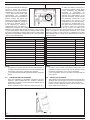
Fig. 11
Fig. 12
Fig. 13
MONTAGGIO NON CORRET-
TO
Accertarsi che il rilevatore sia
montato perpendicolarmente
rispetto al terreno.
Il rilevatore è equipaggiato con
speciali ltri per i disturbi dei
raggi solari; nei limiti del pos-
sibile è comunque consigliata
l’installazione evitando il sole
diretto
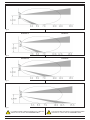
3.7 REGOLAZIONE DELLA DISTANZA DI
RILEVAZIONE
Tramite il pomello di regolazione è possibile regolare il fascio del
PIR basso in modo da ottenere distanze di rilevazione come di
seguito riportate.
Tabella 3
Posizione PIR2 Distanza
A3 m
B5 m
C7 m
D10 m
E15 m
Table 3
PIR2 Position Range
A3 m
B5 m
C7 m
D10 m
E15 m
Fig. 14
Posizione A
WRONG INSTALLATION
Take care to install the detector
perpendicularly to the groung.
The detector is designed to
avoid any light disturbance.
However too strong light as di-
rect sunlight may cause unsta-
ble condition of detector.
It’s recommended to avoid
such type of installation.
3.7 DETECTION RANGE ADJUSTMENT
Use adjusting knob to adjust PIR2 detection length in order to
obtain detection range as shown below
Position A

11
LINCE ITALIA S.p.A.
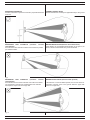
La portata riportata è riferita ai rilevatori con 2 PIR che
diventa di 12 m nel caso del 1896BOBBY-AM/U.
The reported ow rate refers to 2 PIR detectors which
becomes 12 m in the case of 1896BOBBY-AM/U.
Fig. 15
Posizione B Position B
Fig. 16
Posizione C Position C
Fig. 17
Posizione D Position D
Fig. 18
Posizione E Position E

12
LINCE ITALIA S.p.A.
Tabella 6
DIP2 DIP3 SENSIBILITÀ PIR
OFF OFF
PIR bassa sensibilità
OFF ON
PIR media/bassa sensibilità
ON OFF
PIR media/alta sensibilità
ON ON
PIR alta sensibilità
DIP4 DIP5 LOGICA DI FUNZIONAMENTO
(MW DISPONIBILE SOLO PER 1896BOBBY-AM/U)
OFF OFF
PIR1 AND PIR2 AND MW
Nota: utilizzabile nella maggior parte delle installazioni
esterne
OFF ON
(PIR1 OR PIR2) AND MW
Nota: non consigliata in ambienti particolarmente ostili.
ON OFF
PIR1 AND PIR2 (MW esclusa)
Nota: la rilevazione della MW non ha inuenza sulle pre-
stazioni del rilevatore.
ON ON
PIR1 AND MW (PIR2 escluso)
Nota: non consigliata in ambienti particolarmente ostili.
Table 6
DIP2 DIP3 PIR SENSIBILITY
OFF OFF
PIR low sensitivity
OFF ON
PIR medium/low sensitivity
ON OFF
PIR medium/high sensitivity
ON ON
PIR high sensitivity
DIP4 DIP5 WORKING LOGIC
(MW AVAILABLE ONLY FOR 1896BOBBY-AM/U)
OFF OFF
PIR1 AND PIR2 AND MW
Note: it can be used in most outdoor installations.
OFF ON
(PIR1 OR PIR2) AND MW
Note: not recommended in particularly hostile envi-
ronments.
ON OFF
PIR1 AND PIR2 AND MW excluded
Note: the detection of the MW does not affect the per-
formance of the detector.
ON ON
PIR1 AND AND MW PIR2 excluded
Note: not recommended in particularly hostile envi-
ronments.
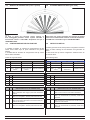
Fig. 19
Le zone in grigio non possono essere coperte; le
zone tratteggiate potranno essere coperte ruotando il
meccanismo interno. Il lobo MW è disponibile solo per il
1896BOBBY-AM/U.
Grey zones can not be protected; the coverage of dashed
zones can be obtained with rotation of internal mechanism.
The MW lobe is available only for 1896BOBBY-AM/U.
3.8 GRAFICO DI COPERTURA (vista in pianta) 3.8 COVERED AREA PATTERN (plan view)
In modalità a batteria, le variazioni di congurazione dei dip
switch hanno effetto dopo la prima rilevazione che genera
allarme.
In modalità WIN le variazioni di congurazione dei dip switch
hanno effetto immediato.
Vedere la seguente tabella.
Tabella 5
DIP OFF ON Funzioni
1LED accessi LED spenti Accensione LED
9Inibizione per 180 s Inibizione per 30 s Durata inibizione
10
Inibizione
dopo 1 evento di
allarme
Inibizione
dopo 2 eventi di
allarme
Intervallo inibizione
3.9 CONFIGURAZIONE DEL RILEVATORE 3.9 DETECTOR SET-UP
In battery-operation mode, the dip switch conguration variations
have an effect following the rst detection that generates an
alarm.
In WIN mode the dip switch conguration variations have an
immediate effect.
See following table.
Table 5
DIP OFF ON Notes
1LED turned ON LED turned OFF LED power-on
9Inhibition for 180 s Inhibition for 30 s Inhibition length
10
Inhibition
After 1 alarm
event
Inhibition After 2
alarm event Inhibition interval

13
LINCE ITALIA S.p.A.
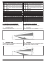
Fig. 20
4. ESEMPIO DI RILEVAMENTO
L’esempio si riferisce al rilevatore settato in triplo AND.
( 1 ) NESSUN ALLARME
L’animale viene rilevato da due delle tre tecnologie (PIR basso
e MW) per cui l’allarme NON si attiva.
4. DETECTING EXAMPLE
The example refers to the detector set in triple AND.
( 1 ) NO ALARM
The pet is detected only by two of the three sensor elements
(lower PIR and MW). The alarm is not enabled.
Fig. 21
( 2 ) NESSUN ALLARME
La persona viene rilevata da due delle tre tecnologie (PIR alto e
MW) per cui l’allarme NON si attiva.
( 2 ) NO ALARM
The body is detected only by two of the three sensor elements
(higher PIR and MW). The alarm is not enabled.
DIP4 DIP5 LOGICA DI FUNZIONAMENTO
(SOLO PER 1897BOBBY-AM/UE E 1929-BOBBY-UE)
OFF OFF
PIR1 AND PIR2
Nota: utilizzabile nella maggior parte delle installazioni
esterne
OFF ON
solo PIR2 (PIR1 escluso)
Nota: utilizzabile nella maggior parte delle installazioni
esterne
ON OFF
solo PIR1 (PIR2 escluso)
Nota: utilizzabile nella maggior parte delle installazioni
esterne
ON ON
non disponibile
DIP6
Non utilizzato
DIP7 DIP8 ANTIMASCHERAMENTO
(solo per 1896BOBBY-AM/U, 1897BOBBY-AM/UE)
OFF OFF
Antimask OFF
OFF ON
Antimask bassa sensbilità
ON OFF
Antimask media sensbilità
ON ON
Antimask alta sensbilità
DIP4 DIP5 LOGIC OF WORKING
(0NLY FOR 1897BOBBY-AM/UE AND 1929-BOBBY-UE)
OFF OFF
PIR1 AND PIR2
Note: it can be used in most outdoor installations.
OFF ON
only PIR2 (PIR1 excluded)
Note: not recommended in particularly hostile envi-
ronments.
ON OFF
only PIR1 (PIR2 excluded)
Note: not recommended in particularly hostile envi-
ronments.
ON ON
not available
DIP6
Not in use
DIP7 DIP8 ANTIMASKING
(only for 1896BOBBY-AM/U, 1897BOBBY-AM/UE)
OFF OFF
Antimask OFF
OFF ON
Antimask low sensibility
ON OFF
Antimask media sensibility
ON ON
Antimask alta sensibility

14
LINCE ITALIA S.p.A.
Fig. 23
5. ACCESSORI DISPONIBILI
5.1 STAFFA
Kit staffa da palo in acciaio inox (art.
001805/00092AA)
5. AVAILABLE ACCESSORIES
5.1 BRACKET
Stainless steel bracket kit for pole
installation (item 001805/00092AA)
5.2 COVER PARAPIOGGIA
Cover parapioggia per la protezione
del rilevatore dagli agenti atmosferici
(art. 1820COVERKIT).
Accessorio consigliato in ambienti
esterni dove la pioggia che si posa
sulla lente potrebbe diminuire drasti-
camente la portata di rilevazione.
5.2 RAIN COVER
Rain cover for the protection of the
detector against weathering (art. 1820
COVERKIT).
Recommended accessory for outdoor
use where the rain on the lens could
drastically decrease the detection range.
Fig. 24
5.3 KIT RISCALDATORE
Kit riscaldatore universale equipaggiato
con sensore di temperatura ed
igrometro. Assorbimento max. 300 mA
(art.1819KR-KIT).
Disponibile anche con il solo sensore di
temperatura (art. 1821KR-KIT/E).
Collegare esclusivamente in parallelo
all’alimentazione WIN.
Non collegarlo in parallalo alla batteria
principale, ne a quella ausiliaria al ne
di non compromettere l’autonomia del ri-
levatore.
5.3 HEATER KIT
Heater kit with hygrometer and
temperature sensor. Absorption max.
300 mA (art. 1819KR-KIT).
Also aviable only with temperature
sensor (Art. 1821KR-KIT/E).
Contect only to the WIN power supply.
Not connect neither to the main bat-
tery or to the auxiliary in order to not
compromise the autonomy of the de-
vice
Fig. 25
Fig. 22
( 3 ) ALLARME
La persona viene rilevata da tutte e tre le tecnologie (PIR basso
+ PIR alto + MW) per cui si attiva lo stato di allarme.
( 3 ) ALARM
The body is detected by all the three sensor elements (PIR lower
+ higher PIR + MW). The alarm is enabled

15
LINCE ITALIA S.p.A.
5.4 STAFFA
La staffa per i rivelatori volumetrici da
esterno 1951-SB5 permette di ruota-
re il fascio di copertura di 5° verso il
muro di installazione nel caso vi fosse
necessità di una rilevazione adiacente
al muro stesso
5.4 BRACKET
The bracket 1951-sb5 for outdoor de-
tectors allows to rotate 5 degrees the
coverage beam towards the installa-
tion walll if you need a detection closer
to thw wall istelf.
Fig. 26
6. RICERCA DEI GUASTI E/O MALFUN-
ZIONAMENTI
Problema Soluzione
I LED non si accendono
appena installata la pila
Vericare la corretta installazione
della pila
Falsi allarmi Il rilevatore non è perpendicolare al
terreno
Il PIR basso è mal regolato, raggiun-
ge distanze superiori a quelle desi-
derate
Oggetti in movimento nell’area pro-
tetta
La sensibilità della MW è al massimo
Non rileva Errata regolazione dei PIR
La sensibilità della MW è al minimo
Altezza di installazione diversa da
quella indicata o dispositivo non per-
pendicolare al terreno
Allarmi continui del
mascheramento
Ostacoli di medie dimensioni a ridos-
so del rilevatore
Regolare la sensibilità AM
7. MANUTENZIONE E VERIFICHE PE-
RIODICHE
Per assicurare il corretto funzionamento del rilevatore è ne-
cessario che la lente venga mantenuta pulita. Una lente non
perfettamente pulita può causare problemi di rivelazioni e/o
problemi alla funzione antimask.
Periodicità: quando necessario o in condizione di sporcizia evi-
dente.
Materiale da utilizzare: panno - acqua senza additivi.
Procedura di pulizia:
ATTENZIONE! Per rimuovere sporcizie particolar-
mente evidenti NON utilizzare prodotti a base di clo-
ro, prodotti abrasivi oppure alcool.
1. Pulire il coperchio e la lente con un panno inumidito con ac-
qua.
2. Ripassare con un panno asciutto.
Trouble Solution
LEDs fail to switch on when
the battery is installed
Check the right installation of the bat-
tery
False alarms The detector is not perpendicular to
the ground
Check if the lower detection area is
wider than your planning
Check if there are objects in move-
ment in the detection area
MW is set at maximum level
No detection The PIRs are not properly adjusted
MW adjustment is set at minimum
level
Wrong installation height or evice not
perpendicular to the ground
Continuous anti-masking
alarms
Medium-sized obstacles close to the
detector
Adjust the AM sensibility
6. TROUBLE SHOOTING
7. MAINTENANCE AND PERIODIC
CHECKS
Keep the lens clean to guarantee proper operation of the
detector.
A lens which is not perfectly clean may cause detection pro-
blems and/or problems to the anti-mask function.
Frequency: when necessary or when clearly dirty.
Material to be used: cloth - water with no additives.
Cleaning procedure:
IMPORTANT!
Do NOT use chlorine-based or abrasive products or
alcohol to remove particularly noticeable dirt.
1. Clean the lid and the lens with a cloth dampened with water.
2. Wipe with a dry cloth.

001530/00925AB Rev. 0
LINCE ITALIA S.p.A
Via Variante di Cancelliera, snc
00072 ARICCIA (Roma)
Tel. +39 06 9301801
Fax +39 06 930180232
www.lince.net
8. SMALTIMENTO E ROTTAMAZIONE
1. Svitare le viti che tengono sso il coperchio frontale e rimuo-
verlo.
2. Dividere le parti in base alla loro tipologia e smaltirle in accor-
do con le leggi vigenti.
ATTENZIONE!
Non disperdere nell’ambiente i componenti ed ogni
altro materiale del prodotto.
Rivolgersi a consorzi abilitati allo smaltimento ed al riciclag-
gio dei materiali.
8. DISPOSAL AND SCRAPPING
1. Unscrew the screws that fasten the front lid and remove it.
2. Divide the parts by type and dispose of them in accordance
with applicable laws.
IMPORTANT!
Do not dispose of the components or any other pro-
duct material in the environment.
Seek the assistance of companies authorised to dispose of
and recycle waste materials.
-
 1
1
-
 2
2
-
 3
3
-
 4
4
-
 5
5
-
 6
6
-
 7
7
-
 8
8
-
 9
9
-
 10
10
-
 11
11
-
 12
12
-
 13
13
-
 14
14
-
 15
15
-
 16
16


Lince 1897BOBBY-AM/UE Istruzioni per l'uso
- Categoria
- Illuminazione di comodità
- Tipo
- Istruzioni per l'uso
- Questo manuale è adatto anche per
in altre lingue
Documenti correlati
-
 Lince 9553-GOLD-BOBBY-AM-E Istruzioni per l'uso
-
 Lince 1875BOBBY-AM/E Istruzioni per l'uso
-
 Lince 1673BOBBY Istruzioni per l'uso
-
 Lince 1947-BOBBY180-E-AM Istruzioni per l'uso
-
 Lince 4058GR868DT Istruzioni per l'uso
-
 Lince 4059GR868ZENITH Istruzioni per l'uso
-
 Lince 1866BABY-BA/E Istruzioni per l'uso
-
 Lince 1967-ES34-Z Istruzioni per l'uso
-
 Lince 9588-GOLD-TXRX-M Istruzioni per l'uso
-
 Lince 1903-RICK-E200 Istruzioni per l'uso