Miller 193401 Manuale del proprietario
- Categoria
- Sistema di saldatura
- Tipo
- Manuale del proprietario
Questo manuale è adatto anche per

Processes
TIG (GTAW) Welding
MIG (GMAW) Welding
COOLPACK 1E/2E
OM-188 412D December 2002
Effective with serial number 193 401
Description
Visit our website at
www.MillerWelds.com

Thank you and congratulations on choosing Miller. Now you can get the
job done and get it done right. We know you don’t have time to do it any
other way.
That’s why when Niels Miller first started building arc welders in 1929,
he made sure his products offered long-lasting value and superior quality.
Like you, his customers couldn’t afford anything less. Miller products had
to be more than the best they could be. They had to be the best you could
buy.
Today, the people that build and sell Miller products continue the
tradition. They’re just as committed to providing equipment and service
that meets the high standards of quality and value established in 1929.
This Owner’s Manual is designed to help you get the most out of your
Miller products. Please take time to read the Safety precautions. They will
help you protect yourself against potential hazards on the worksite. We’ve
made installation and operation quick and easy. With Miller you can
count on years of reliable service with proper maintenance. And if for
some reason the unit needs repair, there’s a Troubleshooting section that
will help you figure out what the problem is. The parts list will then help
you to decide which exact part you may need to fix the problem.
Warranty and service information for your particular model are also
provided.
Miller Electric manufactures a full line of
welders and welding related equipment. For
information on other quality Miller products, contact your local Miller
distributor to receive the latest full line catalog or individual catalog sheets.
Working as hard as you do
− every power source from
Miller is backed by the most
hassle-free warranty in the
business.
From Miller to You

TABLE OF CONTENTS
SECTION 1 − SAFETY PRECAUTIONS−READ BEFORE USING 1. . . . . . . . . .
1-1. Symbol Usage 1. . . . . . . . . . . . . . . . . . . . . . . . . . . . . . . . . . . . . . . . . . . . . . . . .
1-2. Arc Welding Hazards 1. . . . . . . . . . . . . . . . . . . . . . . . . . . . . . . . . . . . . . . . . . .
1-3. Additional Symbols for Installation, Operation, and Maintenance 3. . . . . .
1-4. EMF Information 3. . . . . . . . . . . . . . . . . . . . . . . . . . . . . . . . . . . . . . . . . . . . . . .
SECTION 2 − DEFINITIONS 4. . . . . . . . . . . . . . . . . . . . . . . . . . . . . . . . . . . . . . . . . .
SECTION 3 − INSTALLATION 5. . . . . . . . . . . . . . . . . . . . . . . . . . . . . . . . . . . . . . . . .
3-2. Selecting a Location 5. . . . . . . . . . . . . . . . . . . . . . . . . . . . . . . . . . . . . . . . . . . .
3-3. Connections 6. . . . . . . . . . . . . . . . . . . . . . . . . . . . . . . . . . . . . . . . . . . . . . . . . . .
3-4. Preparing Cooling Unit for Use 7. . . . . . . . . . . . . . . . . . . . . . . . . . . . . . . . . . .
3-5. Connecting Input Power 8. . . . . . . . . . . . . . . . . . . . . . . . . . . . . . . . . . . . . . . .
3-6. Operating Coolant System 8. . . . . . . . . . . . . . . . . . . . . . . . . . . . . . . . . . . . . .
SECTION 4 − MAINTENANCE AND TROUBLESHOOTING 9. . . . . . . . . . . . . . .
4-1. Routine Maintenance 9. . . . . . . . . . . . . . . . . . . . . . . . . . . . . . . . . . . . . . . . . . .
4-2. Troubleshooting 9. . . . . . . . . . . . . . . . . . . . . . . . . . . . . . . . . . . . . . . . . . . . . . .
SECTION 5 − ELECTRICAL DIAGRAM 11. . . . . . . . . . . . . . . . . . . . . . . . . . . . . . . .
SECTION 6 − PARTS LIST 12. . . . . . . . . . . . . . . . . . . . . . . . . . . . . . . . . . . . . . . . . . . .
WARRANTY

dec_con1_usa11/02
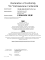
Declaration of Conformity
“CE” Dichiarazione Conformità
Manufactruer’s Name:
Nome del Costruttore:
ITW WELDING PRODUCTS ITALY S.r.l.
Manufacturer’s Address:
Indirizzo Costruttore:
Via Privata Iseo, 6/E
20098 San Giuliano
Milanese, Italy
Declares that this product:
Dichiara che il Prodotto:
COOLPACK 1E/2E
Conforms to the following Directives and Standards:
È Conforme alle seguenti Direttive e Norme.
Directive
Low Voltage: 73/23/EEC
Direttiva bassa tensione: 73/23/CEE
Machinery Directives: 98/37/EEC
Direttiva Macchine: 98/37/CEE
And their amendments 91/368/EEC, 92/31/EEC, 133/04, 93/68/EEC
Aggiornate dalle direttive 91/368/CEE, 92/31/CEE, 133/04, 93/68/CEE
Electromagnetic Compatibility Directives: 89/336/EEC, 92/31/EEC
Compatibilità Elettromagnetica: (EMC) 89/336/CEE, 92/31/CEE
Standard
Safety Requirements for Arc Welding Equipment part 1: EN 60974-1, 1989
Prescrizioni di sicurezza per apparecchi di saldatura ad arco, Sezione 1: EN 60974-1, 1989
Arc Welding Equipment Part 1: Welding Power Sources: IEC 974-1 (April 1995 - Draft revision)
Apparecchi di saldatura ad arco, Sezione 1: Alimentatori per saldatura: IEC 974-1 (Aprile 1995 - Revisione prelimi-
nare)
Electromagnetic compatibility (EMC) Product standard for arc welding equipment: EN50199: December 1995
Norma sulla compatibilità elettromagnetica (EMC) dei prodotti per apparecchi di saldatura ad arco:
EN50199, dicembre 1995
Degrees of Protection provided by Enclosures (IP code): IEC 529: 1989
Grado di protezione fornito dagli involucri (codice IP): IEC 529: 1989
European Contact: Mr. Danilo Fedolfi, Managing Director
In Europa Contattare: ITW WELDING PRODUCTS ITALY S.r.l.
Via Privata Iseo, 6/E
20098 San Giuliano
Milanese, Italy
Telefono: 39(02)982901
Fax: 39(02)98290−203

OM-188 412 Page 1
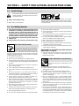
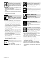
SECTION 1 − SAFETY PRECAUTIONS−READ BEFORE USING
safety_som_woPSS 4/98
1-1. Symbol Usage
Means Warning! Watch Out! There are possible hazards
with this procedure! The possible hazards are shown in
the adjoining symbols.
Y Marks a special safety message.
. Means “Note”; not safety related.
This group of symbols means Warning! Watch Out! possible
ELECTRIC SHOCK, MOVING PARTS, and HOT PARTS hazards.
Consult symbols and related instructions below for necessary actions
to avoid the hazards.
1-2. Arc Welding Hazards
Y The symbols shown below are used throughout this manual to
call attention to and identify possible hazards. When you see
the symbol, watch out, and follow the related instructions to
avoid the hazard. The safety information given below is only
a summary of the more complete safety information found in
the Safety Standards. Read and follow all Safety Standards.
Y Only qualified persons should install, operate, maintain, and
repair this unit.
Y During operation, keep everybody, especially children, away.
ELECTRIC SHOCK can kill.
Touching live electrical parts can cause fatal shocks
or severe burns. The electrode and work circuit is
electrically live whenever the output is on. The input
power circuit and machine internal circuits are also
live when power is on. In semiautomatic or automatic wire welding, the
wire, wire reel, drive roll housing, and all metal parts touching the
welding wire are electrically live. Incorrectly installed or improperly
grounded equipment is a hazard.
D Do not touch live electrical parts.
D Wear dry, hole-free insulating gloves and body protection.
D Insulate yourself from work and ground using dry insulating mats
or covers big enough to prevent any physical contact with the work
or ground.
D Do not use AC output in damp areas, if movement is confined, or if
there is a danger of falling.
D Use AC output ONLY if required for the welding process.
D If AC output is required, use remote output control if present on
unit.
D Disconnect input power or stop engine before installing or
servicing this equipment. Lockout/tagout input power according to
OSHA 29 CFR 1910.147 (see Safety Standards).
D Properly install and ground this equipment according to its
Owner’s Manual and national, state, and local codes.
D Always verify the supply ground − check and be sure that input
power cord ground wire is properly connected to ground terminal in
disconnect box or that cord plug is connected to a properly
grounded receptacle outlet.
D When making input connections, attach proper grounding conduc-
tor first − double-check connections.
D Frequently inspect input power cord for damage or bare wiring −
replace cord immediately if damaged − bare wiring can kill.
D Turn off all equipment when not in use.
D Do not use worn, damaged, undersized, or poorly spliced cables.
D Do not drape cables over your body.
D If earth grounding of the workpiece is required, ground it directly
with a separate cable.
D Do not touch electrode if you are in contact with the work, ground,
or another electrode from a different machine.
D Use only well-maintained equipment. Repair or replace damaged
parts at once. Maintain unit according to manual.
D Wear a safety harness if working above floor level.
D Keep all panels and covers securely in place.
D Clamp work cable with good metal-to-metal contact to workpiece
or worktable as near the weld as practical.
D Insulate work clamp when not connected to workpiece to prevent
contact with any metal object.
SIGNIFICANT DC VOLTAGE exists after removal of
input power on inverters.
D Turn Off inverter, disconnect input power, and discharge input
capacitors according to instructions in Maintenance Section
before touching any parts.
Welding produces fumes and gases. Breathing
these fumes and gases can be hazardous to your
health.
FUMES AND GASES can be hazardous.
D Keep your head out of the fumes. Do not breathe the fumes.
D If inside, ventilate the area and/or use exhaust at the arc to remove
welding fumes and gases.
D If ventilation is poor, use an approved air-supplied respirator.
D Read the Material Safety Data Sheets (MSDSs) and the
manufacturer’s instructions for metals, consumables, coatings,
cleaners, and degreasers.
D Work in a confined space only if it is well ventilated, or while
wearing an air-supplied respirator. Always have a trained watch-
person nearby. Welding fumes and gases can displace air and
lower the oxygen level causing injury or death. Be sure the breath-
ing air is safe.
D Do not weld in locations near degreasing, cleaning, or spraying op-
erations. The heat and rays of the arc can react with vapors to form
highly toxic and irritating gases.
D Do not weld on coated metals, such as galvanized, lead, or
cadmium plated steel, unless the coating is removed from the weld
area, the area is well ventilated, and if necessary, while wearing an
air-supplied respirator. The coatings and any metals containing
these elements can give off toxic fumes if welded.

OM-188 412 Page 2
Arc rays from the welding process produce intense
visible and invisible (ultraviolet and infrared) rays
that can burn eyes and skin. Sparks fly off from the
weld.
ARC RAYS can burn eyes and skin.
D Wear a welding helmet fitted with a proper shade of filter to protect
your face and eyes when welding or watching (see ANSI Z49.1
and Z87.1 listed in Safety Standards).
D Wear approved safety glasses with side shields under your
helmet.
D Use protective screens or barriers to protect others from flash and
glare; warn others not to watch the arc.
D Wear protective clothing made from durable, flame-resistant mate-
rial (leather and wool) and foot protection.
WELDING can cause fire or
explosion.
Welding on closed containers, such as tanks,
drums, or pipes, can cause them to blow up. Sparks
can fly off from the welding arc. The flying sparks, hot
workpiece, and hot equipment can cause fires and
burns. Accidental contact of electrode to metal objects can cause
sparks, explosion, overheating, or fire. Check and be sure the area is
safe before doing any welding.
D Protect yourself and others from flying sparks and hot metal.
D Do not weld where flying sparks can strike flammable material.
D Remove all flammables within 35 ft (10.7 m) of the welding arc. If
this is not possible, tightly cover them with approved covers.
D Be alert that welding sparks and hot materials from welding can
easily go through small cracks and openings to adjacent areas.
D Watch for fire, and keep a fire extinguisher nearby.
D Be aware that welding on a ceiling, floor, bulkhead, or partition can
cause fire on the hidden side.
D Do not weld on closed containers such as tanks, drums, or pipes,
unless they are properly prepared according to AWS F4.1 (see
Safety Standards).
D Connect work cable to the work as close to the welding area as
practical to prevent welding current from traveling long, possibly
unknown paths and causing electric shock and fire hazards.
D Do not use welder to thaw frozen pipes.
D Remove stick electrode from holder or cut off welding wire at
contact tip when not in use.
D Wear oil-free protective garments such as leather gloves, heavy
shirt, cuffless trousers, high shoes, and a cap.
D Remove any combustibles, such as a butane lighter or matches,
from your person before doing any welding.
FLYING METAL can injure eyes.
D Welding, chipping, wire brushing, and grinding
cause sparks and flying metal. As welds cool,
they can throw off slag.
D Wear approved safety glasses with side
shields even under your welding helmet.
BUILDUP OF GAS can injure or kill.
D Shut off shielding gas supply when not in use.
D Always ventilate confined spaces or use
approved air-supplied respirator.
HOT PARTS can cause severe burns.
D Do not touch hot parts bare handed.
D Allow cooling period before working on gun or
torch.
MAGNETIC FIELDS can affect
pacemakers.
D Pacemaker wearers keep away.
D Wearers should consult their doctor before
going near arc welding, gouging, or spot
welding operations.
NOISE can damage hearing.
Noise from some processes or equipment can
damage hearing.
D Wear approved ear protection if noise level is
high.
Shielding gas cylinders contain gas under high
pressure. If damaged, a cylinder can explode. Since
gas cylinders are normally part of the welding
process, be sure to treat them carefully.
CYLINDERS can explode if damaged.
D Protect compressed gas cylinders from excessive heat, mechani-
cal shocks, slag, open flames, sparks, and arcs.
D Install cylinders in an upright position by securing to a stationary
support or cylinder rack to prevent falling or tipping.
D Keep cylinders away from any welding or other electrical circuits.
D Never drape a welding torch over a gas cylinder.
D Never allow a welding electrode to touch any cylinder.
D Never weld on a pressurized cylinder − explosion will result.
D Use only correct shielding gas cylinders, regulators, hoses, and fit-
tings designed for the specific application; maintain them and
associated parts in good condition.
D Turn face away from valve outlet when opening cylinder valve.
D Keep protective cap in place over valve except when cylinder is in
use or connected for use.
D Read and follow instructions on compressed gas cylinders,
associated equipment, and CGA publication P-1 listed in Safety
Standards.

OM-188 412 Page 3
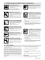
1-3. Additional Symbols for Installation, Operation, and Maintenance
FIRE OR EXPLOSION hazard.
D Do not install or place unit on, over, or near
combustible surfaces.
D Do not install unit near flammables.
D Do not overload building wiring − be sure power supply system is
properly sized, rated, and protected to handle this unit.
FALLING UNIT can cause injury.
D Use lifting eye to lift unit only, NOT running
gear, gas cylinders, or any other accessories.
D Use equipment of adequate capacity to lift and
support unit.
D If using lift forks to move unit, be sure forks are
long enough to extend beyond opposite side of
unit.
OVERUSE can cause OVERHEATING
D Allow cooling period; follow rated duty cycle.
D Reduce current or reduce duty cycle before
starting to weld again.
D Do not block or filter airflow to unit.
STATIC (ESD) can damage PC boards.
D Put on grounded wrist strap BEFORE handling
boards or parts.
D Use proper static-proof bags and boxes to
store, move, or ship PC boards.
MOVING PARTS can cause injury.
D Keep away from moving parts.
D Keep away from pinch points such as drive
rolls.
WELDING WIRE can cause injury.
D Do not press gun trigger until instructed to do
so.
D Do not point gun toward any part of the body,
other people, or any metal when threading
welding wire.
MOVING PARTS can cause injury.
D Keep away from moving parts such as fans.
D Keep all doors, panels, covers, and guards
closed and securely in place.
H.F. RADIATION can cause interference.
D High-frequency (H.F.) can interfere with radio
navigation, safety services, computers, and
communications equipment.
D Have only qualified persons familiar with
electronic equipment perform this installation.
D The user is responsible for having a qualified electrician prompt-
ly correct any interference problem resulting from the installa-
tion.
D If notified by the FCC about interference, stop using the
equipment at once.
D Have the installation regularly checked and maintained.
D Keep high-frequency source doors and panels tightly shut, keep
spark gaps at correct setting, and use grounding and shielding to
minimize the possibility of interference.
ARC WELDING can cause interference.
D Electromagnetic energy can interfere with
sensitive electronic equipment such as
computers and computer-driven equipment
such as robots.
D Be sure all equipment in the welding area is
electromagnetically compatible.
D To reduce possible interference, keep weld cables as short as
possible, close together, and down low, such as on the floor.
D Locate welding operation 100 meters from any sensitive elec-
tronic equipment.
D Be sure this welding machine is installed and grounded
according to this manual.
D If interference still occurs, the user must take extra measures
such as moving the welding machine, using shielded cables,
using line filters, or shielding the work area.
1-4. EMF Information
Considerations About Welding And The Effects Of Low Frequency
Electric And Magnetic Fields
Welding current, as it flows through welding cables, will cause electro-
magnetic fields. There has been and still is some concern about such
fields. However, after examining more than 500 studies spanning 17
years of research, a special blue ribbon committee of the National
Research Council concluded that: “The body of evidence, in the
committee’s judgment, has not demonstrated that exposure to power-
frequency electric and magnetic fields is a human-health hazard.”
However, studies are still going forth and evidence continues to be
examined. Until the final conclusions of the research are reached, you
may wish to minimize your exposure to electromagnetic fields when
welding or cutting.
To reduce magnetic fields in the workplace, use the following
procedures:
1. Keep cables close together by twisting or taping them.
2. Arrange cables to one side and away from the operator.
3. Do not coil or drape cables around your body.
4. Keep welding power source and cables as far away from opera-
tor as practical.
5. Connect work clamp to workpiece as close to the weld as possi-
ble.
About Pacemakers:
Pacemaker wearers consult your doctor first. If cleared by your doctor,
then following the above procedures is recommended.

OM-188 412 Page 4
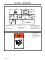
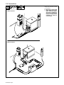
SECTION 2 − DEFINITIONS
1 Warning! Watch Out! There are
possible hazards as shown by the
symbols.
2 Disconnect input plug or power
before working on machine.
3 Wear safety glasses with side
shields.
4 Plugged filter or hoses cause
overheating and damage.
5 Read Owner’s Manual.
6 Check and clean filter every 100
hours; also check condition of hoses.
7 Use Blue Liquid (B) 050024004 when
MIG (GMAW) welding, TIG (GTAW)
welding using high frequency, and
where liquid contacts aluminum parts.
21 3
6
4
7
5
1 Warning! Watch Out! There
are possible hazards as
shown by the symbols.
2 Moving parts, such as fans,
can cut fingers and hands and
cause injury. Keep away from
moving parts.
4/96
S-176 106
1
2

OM-188 412 Page 5
SECTION 3 − INSTALLATION
3-1. Specifications
Model
Coolant Tank
Capacity
Maximum
Cooling Capacity
Input Power
Input Power
Cord with Plug
Overall
Dimensions
Net Weight
1E 5 L (2 gal) 11,000 BTU/hr
1.2 L/min
(1.25 qt/min)
Single-Phase
115 VAC
50/60 Hz
2.3 Amperes
3 m (10 ft) Length: 238 mm
Height: 657 mm
Width: 248 mm
17 kg
2E 5 L (2 gal) 11,000 BTU/hr
1.2 L/min
(1.25 qt/min)
Single-Phase
230 VAC
50/60 Hz
1.2 Amperes
3 m (10 ft) Length: 238 mm
Height: 657 mm
Width: 248 mm
17 kg
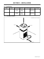
3-2. Selecting a Location
Position unit so air can circulate.
500 mm
500 mm
500 mm

OM-188 412 Page 6
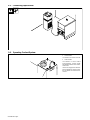
3-3. Connections
To prevent overheating, make sure
cooling unit is positioned so airflow
is not restricted.
Y When using coolant system
with a welding power source
with a water valve, bypass
water valve on welding pow-
er source by connecting di-
rectly to torch/gun to avoid
overheating, or damage to
coolant system.
GTAW Connections
GMAW Connections

OM-188 412 Page 7
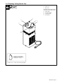
3-4. Preparing Cooling Unit for Use
1 Power Cord
2 Filler Cover
Use table to select proper coolant,
and fill tank. Keep coolant level full.
3 Power Switch
4 Coolant Out Fitting
5 Coolant In Fitting
6 Flow Indicator
Bluliquid No. 050024004**;
Distilled or Deionized Water
OK above 0° C (32° F)
**Protects to -37° F (-38°C) and resist algae growth.
Coolant
4
5
1
2
3
6

OM-188 412 Page 8
3-5. Connecting Input Power
3-6. Operating Coolant System
1 Power Switch
Use switch to turn unit On and Off.
2 Flow Indicator
Use indicator to check coolant
pump operation. Coolant should
flow through indicator when Power
switch is On.
If hoses are clogged, turn Off unit to
prevent damage to coolant system.
Do not operate unit until hoses are
cleared.
1
2

OM-188 412 Page 9
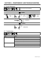
SECTION 4 − MAINTENANCE AND TROUBLESHOOTING
4-1. Routine Maintenance
Y Disconnect power before maintaining.
6 Months
Replace
cracked
parts
Replace
unreadable
labels
Change
Coolant (if
using water)
Blow Out Heat
Exchanger Fins
12 Months
Change Coolant (if
using Blue Liquid)
4-2. Troubleshooting
Trouble Remedy
Coolant system does not work.
Be sure input power cord is plugged in to energized receptacle.
Check line fuses or circuit breaker, and replace or reset if necessary.
Motor overheated. Unit starts running when motor has cooled.
Have Factory Authorized Service Agent check Power switch and motor.
Decreased or no coolant flow.
Add coolant.
Check for clogged hoses or coolant filter.
Disconnect pump, and check for sheared coupling. Replace coupling if necessary.

OM-188 412 Page 10
Notes

OM-188 412 Page 11
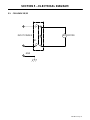
SECTION 5 − ELECTRICAL DIAGRAM
5-1. COOLPACK 1E/2E
MP
S1
GND
INPUT POWER
MOTOR

OM-188 412 Page 12
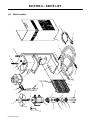
SECTION 6 − PARTS LIST
1
2
34
3
10
12
13
14
15
16
17
19
20
11
21
8
23
7
9
22
32
4
5
26
30
27
25
31
18
6-1. Main Assembly
33
32
33

OM-188 412 Page 13
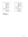
Item
Dia
Ref. Code Qty.Dwg Item
Dia
Ref. Code Qty.Dwg
1 116121078 NO.27.0.1 1
2 117026068 NO.27.1 1
3 027042001 OQ.2.1 1
4 S1 056067157 MQ.0.0.1 1
5 756089008 DZ.24.0.28 1
7 656079018 OQ.2.1.2 2
8 656049051 OQ.2.1.1 2
9 156019194 1
10 356078029 UO.15.0.6 1
11 656003013 NB.25.0.1 1
12 056082080 NB.25.4.16 1
13 MP 057011033 NB.25.3 1
(230V-50/60 Hz)
13 MP 057011034 NB.25.4 1
(115V-50/60 Hz)
14 556045006 NB.25.4.1 1
14 556045007 NB.25.4.22 1
15 956023009 NB.25.4.4 1
16 156013049 NB.25.4.3 1
17 156023149 NB.25.4.9 1
17 156023162 NB.25.4.23 1
18 556078006 NB.25.4.2 1
18 556078007 NB.25.4.24 1
19 656021240 NB.25.4.7 1
19 656021252 NB.25.4.25 1
20 556007006 NB.25.4.11 1
20 556007007 NB.25.4.26 1
21 156019689 NB.25.4.8 4
22 Tube (black) 650020117 0.97m
23 Tube 650020125 0.78m
(transparent)
25 Tube (out) 027061013 NO.27.3 1
26 556049356 NO.27.3.1 2
27 Tube (in) 027061013 NO.27.4 1
30 000073690 EF.0.0.29 1
31 027112065 NB.25.2 1
32 Red 556049368 XF.1.0.7 2
33 Blue 566049369 XF.1.0.8 2
34 056082092 NO.27.0.4 1
Accessories
BLULIQUID (DRW MI.0.5)
(cod. 050024004)

Notes

Effective January 1, 2002
This limited warranty supersedes all previous Miller warranties and is exclusive with no other
guarantees or warranties expressed or implied.
LIMITED WARRANTY − Subject to the terms and conditions
below, Miller Europe S.r.l., Milan Italy, warrants to its original
retail purchaser that new Miller equipment sold after the
effective date of this limited warranty is free of defects in
material and workmanship at the time it is shipped by Miller.
THIS WARRANTY IS EXPRESSLY IN LIEU OF ALL OTHER
WARRANTIES, EXPRESS OR IMPLIED, INCLUDING THE
WARRANTIES OF MERCHANTABILITY AND FITNESS.
Within the warranty periods listed below, Miller will repair or
replace any warranted parts or components that fail due to
such defects in material or workmanship. Miller must be
notified in writing within thirty (30) days of such defect or
failure, at which time Miller will provide instructions on the
warranty claim procedures to be followed.
Miller shall honor warranty claims on warranted equipment
listed below in the event of such a failure within the warranty
time periods. All warranty time periods start on the date that
the equipment was delivered to the original retail purchaser,
or one year after the equipment is sent to a European
distributor or eighteen months after the equipment is sent to
an International distributor.
1. 5 Years Parts − 3 Years Labor
* Original main power rectifiers
* Inverters (input and output rectifiers only)
2. 3 Years — Parts and Labor
* Transformer/Rectifier Power Sources
* Plasma Arc Cutting Power Sources
* Semi-Automatic and Automatic Wire Feeders
* Inverter Power Supplies
* Intellitig
* Engine Driven Welding Generators except Panther
(NOTE: Engines are warranted separately by the
engine manufacturer.)
3. 2 year − Parts and Labor (Panther only)
(NOTE: Engines are warranted separately by the
engine manufacturer.)
4. 1 year − Parts and Labor unless specified
* DS-2 Feeder
* Motor Driven Guns (w/exception of Spoolguns)
* Process Controllers
* Positioners and Controllers
* Automatic Motion Devices
* RFCS Foot Controls
* IHPS Power Sources
* Water Coolant Systems
* Flowgaruge and Flowmeter Regulators (No Labor)
* HF Units
* Grids
* Maxstar 140
* Spot Welders
* Load Banks
* Miller Cyclomatic Equipment
* Running Gear/Trailers
* Plasma Cutting Torches (except APT & SAF
Models)
* Field Options
(NOTE: Field options are covered under True Blue
for the remaining warranty period of the product they
are installed in, or for a minimum of one year —
whichever is greater.)
5 6 Months — Batteries
6. 90 Days — Parts
* MIG Guns/TIG Torches
* Induction heating coils and blankets
* APT, ZIPCUT & PLAZCUT Model Plasma Cutting
Torches
* Remote Controls
* Accessory Kits
* Replacement Parts (No labor)
* Spoolmate Spoolguns
* Canvas covers
Miller’s True Blue Limited Warranty shall not apply to:
1. Consumable components; such as contact tips,
cutting nozzles, contactors, brushes, slip rings,
relays or parts that fail due to normal wear.
2. Items furnished by Miller, but manufactured by others,
such as engines or trade accessories. These items are
covered by the manufacturer’s warranty, if any.
3. Equipment that has been modified by any party other
than Miller, or equipment that has been improperly
installed, improperly operated or misused based upon
industry standards, or equipment which has not had
reasonable and necessary maintenance, or equipment
which has been used for operation outside of the
specifications for the equipment.
MILLER PRODUCTS ARE INTENDED FOR PURCHASE
AND USE BY COMMERCIAL/INDUSTRIAL USERS AND
PERSONS TRAINED AND EXPERIENCED IN THE USE
AND MAINTENANCE OF WELDING EQUIPMENT.
In the event of a warranty claim covered by this warranty, the
exclusive remedies shall be, at Miller’s option: (1) repair; or
(2) replacement; or, where authorized in writing by Miller in
appropriate cases, (3) the reasonable cost of repair or
replacement at an authorized Miller service station; or (4)
payment of or credit for the purchase price (less reasonable
depreciation based upon actual use) upon return of the
goods at customer’s risk and expense. Miller’s option of
repair or replacement will be F.O.B., Factory at Appleton,
Wisconsin, or F.O.B. at a Miller authorized service facility as
determined by Miller. Therefore no compensation or
reimbursement for transportation costs of any kind will be
allowed.
TO THE EXTENT PERMITTED BY LAW, THE REMEDIES
PROVIDED HEREIN ARE THE SOLE AND EXCLUSIVE
REMEDIES. IN NO EVENT SHALL MILLER BE LIABLE
FOR DIRECT, INDIRECT, SPECIAL, INCIDENTAL OR
CONSEQUENTIAL DAMAGES (INCLUDING LOSS OF
PROFIT), WHETHER BASED ON CONTRACT, TORT OR
ANY OTHER LEGAL THEORY.
ANY EXPRESS WARRANTY NOT PROVIDED HEREIN
AND ANY IMPLIED WARRANTY, GUARANTY OR
REPRESENTATION AS TO PERFORMANCE, AND ANY
REMEDY FOR BREACH OF CONTRACT TORT OR ANY
OTHER LEGAL THEORY WHICH, BUT FOR THIS
PROVISION, MIGHT ARISE BY IMPLICATION,
OPERATION OF LAW, CUSTOM OF TRADE OR COURSE
OF DEALING, INCLUDING ANY IMPLIED WARRANTY OF
MERCHANTABILITY OR FITNESS FOR PARTICULAR
PURPOSE, WITH RESPECT TO ANY AND ALL
EQUIPMENT FURNISHED BY MILLER IS EXCLUDED
AND DISCLAIMED BY MILLER.
Some states in the U.S.A. do not allow limitations of how long
an implied warranty lasts, or the exclusion of incidental,
indirect, special or consequential damages, so the above
limitation or exclusion may not apply to you. This warranty
provides specific legal rights, and other rights may be
available, but may vary from state to state.
In Canada, legislation in some provinces provides for certain
additional warranties or remedies other than as stated
herein, and to the extent that they may not be waived, the
limitations and exclusions set out above may not apply. This
Limited Warranty provides specific legal rights, and other
rights may be available, but may vary from province to
province.
milan_warr 10/02

PRINTED IN USA 2002 Miller Electric Mfg. Co. 10/02
Miller Europe
Italy
Phone: 39 (0) 2982901
European Headquarters −
United Kingdom
Phone: 44 (0) 1204-593493
FAX: 44 (0) 1204-598066
Miller Electric Mfg. Co.
An Illinois Tool Works Company
1635 West Spencer Street
Appleton, WI 54914 USA
International Headquarters−USA
Phone: 414-735-4505
USA & Canada FAX: 920-735-4134
International FAX: 920-735-4125
Model Name Serial/Style Number
Purchase Date (Date which equipment was delivered to original customer.)
Distributor
Address
Country Zip/Postal Code
Please complete and retain with your personal records.
Owner’s Record
-
 1
1
-
 2
2
-
 3
3
-
 4
4
-
 5
5
-
 6
6
-
 7
7
-
 8
8
-
 9
9
-
 10
10
-
 11
11
-
 12
12
-
 13
13
-
 14
14
-
 15
15
-
 16
16
-
 17
17
-
 18
18
-
 19
19
-
 20
20


Miller 193401 Manuale del proprietario
- Categoria
- Sistema di saldatura
- Tipo
- Manuale del proprietario
- Questo manuale è adatto anche per
in altre lingue
- English: Miller 193401 Owner's manual
Documenti correlati
-
Miller KH458759 Manuale del proprietario
-
-
-
-
-
-
-
-
-
