
M211860EN-C
User Guide
Vaisala VaiNet Access Point
AP10

PUBLISHED BY
Vaisala Oyj
Vanha Nurmijärventie 21, FI-01670 Vantaa, Finland
P.O. Box 26, FI-00421 Helsinki, Finland
+358 9 8949 1
Visit our Internet pages at www.vaisala.com.
© Vaisala Oyj 2019
No part of this document may be
reproduced, published or publicly
displayed in any form or by any
means, electronic or mechanical
(including photocopying), nor
may its contents be modified,
translated, adapted, sold or
disclosed to a third party without
prior written permission of the
copyright holder. Translated
documents and translated
portions of multilingual
documents are based on the
original English versions. In
ambiguous cases, the English
versions are applicable, not the
translations.
The contents of this document are
subject to change without prior
notice.
Local rules and regulations may
vary and they shall take
precedence over the information
contained in this document.
Vaisala makes no representations
on this document’s compliance
with the local rules and
regulations applicable at any
given time, and hereby disclaims
any and all responsibilities related
thereto.
This document does not create
any legally binding obligations for
Vaisala towards customers or end
users. All legally binding
obligations and agreements are
included exclusively in the
applicable supply contract or the
General Conditions of Sale and
General Conditions of Service of
Vaisala.
This product contains software
developed by Vaisala or third
parties. Use of the software is
governed by license terms and
conditions included in the
applicable supply contract or, in
the absence of separate license
terms and conditions, by the
General License Conditions of
Vaisala Group.
This product may contain open
source software (OSS)
components. In the event this
product contains OSS
components, then such OSS is
governed by the terms and
conditions of the applicable OSS
licenses, and you are bound by
the terms and conditions of such
licenses in connection with your
use and distribution of the OSS in
this product. Applicable OSS
licenses are included in the
product itself or provided to you
on any other applicable media,
depending on each individual
product and the product items
delivered to you.

Table of Contents
1. About This Document................................................................................... 5
1.1 Version Information.......................................................................................... 5
1.2 Related Manuals................................................................................................5
1.3 Documentation Conventions...........................................................................5
1.4 Trademarks........................................................................................................ 6
2. Product Overview........................................................................................... 7
2.1 Overview of AP10 Access Point.......................................................................7
2.2 AP10 Parts..........................................................................................................8
2.3 VaiNet Devices in viewLinc Monitoring System............................................ 9
2.3.1 VaiNet Protocol..........................................................................................9
2.3.2 Data Transfer in a VaiNet Network.........................................................10
2.4 Time Synchronization.......................................................................................11
2.5 Network Security..............................................................................................11
2.6 Power Supply.................................................................................................... 11
2.7 Remote Management......................................................................................12
2.8 Regulatory Compliance.................................................................................. 13
2.8.1 FCC Compliance Statement.................................................................... 13
2.8.2 ISED Compliance Statement...................................................................14
2.8.3 EU Declaration of Conformity.................................................................14
2.8.4 UAE Compliance.......................................................................................16
2.9 Symbols Used in AP10 Product Markings.....................................................16
2.10 ESD Protection.................................................................................................17
3. Installation........................................................................................................ 18
3.1 AP10 Installation Location and Range.......................................................... 18
3.1.1 Mounting in Plenum Space..................................................................... 18
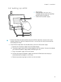
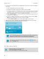
3.2 Setting Up AP10...............................................................................................19
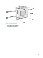
3.3 Mounting AP10............................................................................................... 20
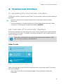
4. Touchscreen Interface.................................................................................23
4.1 Accessing the Touchscreen Interface...........................................................23
4.2 Overview of Touchscreen Interface..............................................................23
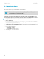
5. Web Interface.................................................................................................26
5.1 Accessing the Web Interface........................................................................ 26
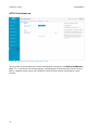
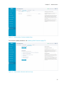
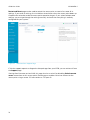
5.2 Overview of Web Interface............................................................................27
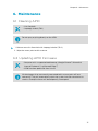
6. Maintenance....................................................................................................35
6.1 Cleaning AP10................................................................................................. 35
6.2 Updating AP10 Firmware...............................................................................35
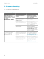
7. Troubleshooting............................................................................................ 38
7.1 Problem Situations.........................................................................................38
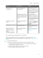
7.2 Verifying Operation of AP10......................................................................... 39
7.3 Performing a Factory Reset..........................................................................40
Table of Contents
1

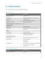
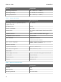
8. Technical Data.................................................................................................41
8.1 AP10 Technical Specification......................................................................... 41
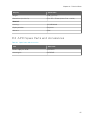
8.2 AP10 Spare Parts and Accessories............................................................... 43
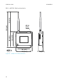
8.3 AP10 Dimensions............................................................................................44
Technical Support........................................................................................... 45
Warranty............................................................................................................45
Recycling........................................................................................................... 45
AP10 User Guide M211860EN-C
2

List of Figures
Figure 1 AP10 in the viewLinc Monitoring System....................................................7
Figure 2 Front......................................................................................................................8
Figure 3 Connector Panel................................................................................................ 8
Figure 4 Rear.......................................................................................................................9
Figure 5 AP10 Remote Management Using viewLinc Enterprise Server...........12
Figure 6 AP10 Properties in viewLinc..........................................................................13
Figure 7 AP10 Mounting Methods................................................................................21
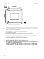
Figure 8 AP10 Screw Mounting Dimensions.............................................................22
Figure 9 Touch Interface Home Screen......................................................................23
Figure 10 Touch Interface Data Logger Information Screen..................................24
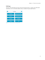
Figure 11 Touch Interface Settings Menu....................................................................25
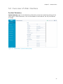
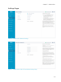
Figure 12 Web Interface System Summary Page......................................................27
Figure 13 Web Interface Data Loggers Page............................................................. 28
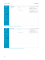
Figure 14 Web Interface Network Settings................................................................ 29
Figure 15 Web Interface DNS, NTP, and VaiNet Settings Page.............................29
Figure 16 Web Interface viewLinc Settings Page.....................................................30
Figure 17 Web Interface Installation Mode Settings Page.....................................30
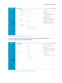
Figure 18 Web Interface Security Settings Page....................................................... 31
Figure 19 Web Interface Display and LED Settings Page........................................31
Figure 20 Web Interface Backup and Restore Page.................................................32
Figure 21 Web Interface Firmware Update Page......................................................33
Figure 22 Web Interface Restart and Reset Page.....................................................33
Figure 23 Web Interface Support Page....................................................................... 34
Figure 24 Firmware Update Page in Web Interface.................................................36
Figure 25 AP10 Access Point Dimensions...................................................................44
List of Figures
3

List of Tables
Table 1 Document Versions (English)........................................................................... 5
Table 2 Related Manuals....................................................................................................5
Table 3 AP10 Power Supply Specifications..................................................................11
Table 4 Symbols Used in AP10 Product Markings.................................................... 16
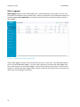
Table 5 Troubleshooting Table...................................................................................... 38
Table 6 Wireless................................................................................................................. 41
Table 7 Operating Environment.....................................................................................41
Table 8 Inputs and Outputs............................................................................................42
Table 9 Mechanical Specifications............................................................................... 42
Table 10 Spare Parts and Accessories...........................................................................43
AP10 User Guide M211860EN-C
4

1. About This Document
1.1 Version Information
Table 1 Document Versions (English)
Document Code Date Description
M211860EN-C February 2019 This document. Updated regulatory compliance
information and sections Overview of Web Interface
(page 27) and Updating AP10 Firmware (page 35).
M211860EN-B July 2018 Previous version. Updated descriptions of touchscreen
interface and web interface.
M211860EN-A May 2018 First version.
1.2 Related Manuals
Table 2 Related Manuals
Document Code Name
M211821EN AP10 Access Point Quick Guide
M211820EN viewLinc Monitoring System Setup Guide
M211975EN viewLinc Enterprise Server User Guide
M211822EN RFL100 Data Logger Quick Guide
M211861EN RFL100 Data Logger User Guide
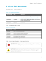
1.3 Documentation Conventions
Warning alerts you to a serious hazard. If you do not read and
follow instructions carefully at this point, there is a risk of injury or even death.
WARNING!
Caution warns you of a potential hazard. If you do not read and
follow instructions carefully at this point, the product could be damaged or
important data could be lost.
CAUTION!
Chapter 1 – About This Document
5

Note highlights important information on using the product.
Tip gives information for using the product more eciently.
Lists tools needed to perform the task.
Indicates that you need to take some notes during the task.
1.4 Trademarks
Vaisalaâ is a registered trademark of Vaisala Oyj.
The LoRa
™
name and associated logo are trademarks of Semtech Corporation or its
subsidiaries.
All other product or company names that may be mentioned in this publication are trade
names, trademarks, or registered trademarks of their respective owners.
AP10 User Guide M211860EN-C
6

2. Product Overview
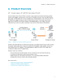
2.1 Overview of AP10 Access Point
Vaisala VaiNet Access Point AP10 is a wireless access point that collects data from VaiNet
wireless data loggers and transfers it to viewLinc Enterprise Server using a wired Ethernet
connection. AP10 implements Vaisala's proprietary VaiNet protocol. It can connect up to 32
RFL100 Data Loggers to Vaisala viewLinc Monitoring System. The wireless connection
operates on 868 MHz or 915 MHz frequency band depending on the model. For more
information on viewLinc system installation, see viewLinc Setup Guide (M211820EN).
viewLinc
Enterprise Server
AP10
Access Point
RFL100
Data Loggers
VaiNet wireless
>100 m (328 ft) range
NTP Server
Wired
network
Figure 1 AP10 in the viewLinc Monitoring System
AP10 can be powered from the Ethernet connector using Power over Ethernet (PoE) or from
the power supply connector using the included AC/DC adapter. If both power sources are
connected, the AC/DC adapter is utilized to power the device. AP10 is IP22 rated, and is
suitable for indoor industrial applications.
AP10 has two user interfaces:
• Touch interface on the front panel. Use this interface to set up the device during
installation and to locally check the connection status.
• Web interface via the Ethernet connection. This interface provides advanced
configuration features and can be accessed remotely.
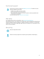
More Information
‣
Overview of Touchscreen Interface (page 23)
‣
Overview of Web Interface (page 27)
‣
AP10 Technical Specification (page 41)
Chapter 2 – Product Overview
7

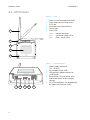
2.2 AP10 Parts
1
2
3
4
5
Figure 2 Front
1 Antenna. Can be rotated and tilted.
2 Screw holes for mounting (4 pcs),
Ø 3.2 mm
3 Ventilation hole (do not cover)
4 Touchscreen
5 Status LED:
Green Normal operation
Blue Installation mode active
Red Error - check status
1 2 3 4 5
Figure 3 Connector Panel
1 Power supply connector
(10 ... 30 VDC)
2 Service port (micro-USB)
3 USB port for hardware expansion
(USB type A)
4 Reset button. Push to restart, push
and hold to revert AP10 to factory
settings.
5 RJ-45 Ethernet port. Can be powered
by Power over Ethernet (PoE).
AP10 User Guide M211860EN-C
8

1
2
2
3
Figure 4 Rear
1 Product label
2 Holes for mounting with tie wraps
3 Housing screws (do not remove)
2.3 VaiNet Devices in viewLinc Monitoring System
VaiNet access points create links between Ethernet and Vaisala devices using the VaiNet
protocol. Wireless device registration is handled by viewLinc Enterprise Server. Whenever a
new data logger is added to the system, it is automatically identified by an access point, which
forwards the data logger’s information to the server. Once accepted in the system, data
loggers will stay synchronized, even in situations where other nearby VaiNet networks overlap.
Redundancy is achieved by allowing load distribution between VaiNet access points which
share multiple data loggers in range.
VaiNet access points transfer measurement data from the data loggers to viewLinc Enterprise
Server. Both access point and viewLinc Enterprise Server verify that the data has been
received correctly. Once the data has been verified, it is stored to the secure database where it
is protected from tampering and loss.
If data flow is interrupted by a network outage, the data transfer will resume when the outage
is resolved. Local memory of the data logger is used to store the data while waiting for a
connection to viewLinc Enterprise Server. RFL100 Data Logger has enough local memory for
30 days of measurement.
2.3.1 VaiNet Protocol
Vaisala’s VaiNet wireless protocol is based on LoRa™ technology. This technology has been
licensed by Vaisala for monitoring purposes, and further enhanced additional protocol layers
to produce a robust and reliable wireless signal for environmental monitoring. The protocol is
proprietary, and cannot be used with 802.11 Wi-Fi devices. VaiNet wireless devices always
require a VaiNet wireless access point.
VaiNet radio communication uses a modulated, low-power signal at sub-GHz frequencies to
provide better signal propagation in environmental monitoring applications. VaiNet provides
all the benefits of spread spectrum wireless technology including resistance to interference,
interception and multipath fading (reflections). Using the chirp signal to spread the RF energy
over a wider band allows for reliable communications even when signal levels are below the
background noise floor. It also reduces disruptions from overlapping signals on same
frequencies.
Chapter 2 – Product Overview
9

VaiNet wireless devices are not limited to using a single access point. If multiple access points
are available, VaiNet devices can switch access points to maintain their connection to the
viewLinc Monitoring System. The strength of the wireless signal is used to determine the
optimum network data path.
Wireless transmissions between VaiNet devices are encrypted to protect against
eavesdropping, data tampering, and transfer errors.
2.3.2 Data Transfer in a VaiNet Network
VaiNet protocol and VaiNet devices are designed for power-ecient operation. To save energy
VaiNet network transfers data at set intervals, which may be apparent to the user as longer
data transfer times before the data is available on viewLinc Monitoring System.
Intermittent Radio Connections
Access points take turns communicating in a two-minute cycle, and connected data loggers
send their measurement data to their connected access point every four minutes. This
introduces the following scenarios:
• Data loggers that are not currently connected (new devices or ones that have fallen out of
radio contact) scan for available access points for a complete cycle before they can
decide what is the optimal access point for them. Connection attempts typically take at
least a couple of minutes. Additionally, some joining scenarios may take multiple
attempts. For example, when filling a single access point up to its full capacity of 32 data
loggers, it may take an hour for the last data logger to successfully connect to the access
point.
• Access points request missing data and issue management commands to data loggers
within their communication window. Transferring a full month's worth of measurement
data from 32 data loggers using one access point takes several hours.
Data Logger Scanning Interval
Scanning for available access points consumes power. To prevent repeated scanning from
draining their batteries, RFL100 Data Loggers shut down their radio temporarily if they can
find no access points to join. They will resume scanning after a waiting interval that gets
progressively longer if they keep failing to find an access point. The maximum interval is 8
hours and 30 minutes.
This means that when access points become available after an outage, it may take several
hours for data loggers to discover them. This is why you should always keep your access points
powered up, and why you should start your network installation by installing the viewLinc
Enterprise Server and access points first.
You can manually wake up the radio of an RFL100 Data Logger by pressing its
Refresh button. The button is located next to the service port under the silicone
plug.
AP10 User Guide M211860EN-C
10

2.4 Time Synchronization
AP10 requires accurate time to operate its VaiNet wireless connection, and to maintain correct
time on the connected data loggers. To achieve the accurate time, AP10 synchronizes with
Network Time Protocol (NTP) servers. The hostnames of the default NTP servers are:
0.pool.ntp.org
1.pool.ntp.org
2.pool.ntp.org
3.pool.ntp.org
Reaching the default NTP servers requires an internet connection. To allow the AP10 to
operate without an internet connection, replace one of the default NTP server addresses with
the address of your local NTP server.
AP10 has a supercapacitor as a backup power source for its realtime clock. If AP10 is left
without power for more than a day, the realtime clock will lose its time. If this happens AP10
will have to synchronize its clock with the NTP servers before it can operate its radio. This is
typically the case when an AP10 is installed - it needs to synchronize its clock before it can
start to connect VaiNet data loggers. Synchronization is also needed due to clock drift if the
NTP servers cannot be reached for more than three weeks.
Synchronizing with the NTP servers typically takes several minutes, during which
time the access point will show the NTP connection error. If you have just turned
on your access point or changed its NTP server configuration, it is normal to see
the error for up to 15 minutes.
2.5 Network Security
AP10 Access Point is intended to be connected to a secure internal network, not directly to the
internet.
2.6
Power Supply
A DC power supply (Vaisala item 244784SP) is included with every AP10 Access Point.
Table 3 AP10 Power Supply Specifications
Property Specification
Operating voltage 10 ... 30 VDC
Output power min. 13 W
Output current min. 1.3 A
Chapter 2 – Product Overview
11

Property Specification
Output connector Locking type female coaxial connector with
positive 2.0 mm center pin
Operating temperature range -20 ... +60 °C (-4 ... +140 °F)
Operating humidity range 0 ... 95 %RH, non-condensing
Certifications and approvals • Certified to IEC 60950-1 or IEC 62368-1
• Approved for use in your country
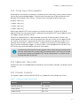
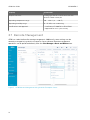
2.7 Remote Management
AP10 has a web interface for remote management. Additionally, some settings can be
remotely managed using viewLinc Enterprise Server software. Remote management
operations can be performed directly from the Sites Manager > Hosts and Devices tree.
Figure 5 AP10 Remote Management Using viewLinc Enterprise Server
AP10 User Guide M211860EN-C
12

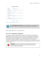
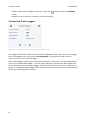
Figure 6 AP10 Properties in viewLinc
Select Sites Manager > Show hosts to see the IP addresses of all connected hosts.
Select the IP address of any AP10 to open its web interface in your browser.
2.8 Regulatory Compliance
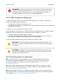
2.8.1 FCC Compliance Statement
This equipment has been tested and found to comply with the limits for a Class A digital
device, pursuant to part 15 of the FCC Rules. These limits are designed to provide reasonable
protection against harmful interference when the equipment is operated in a commercial
environment. This equipment generates, uses, and can radiate radio frequency energy and, if
not installed and used in accordance with the instruction manual, may cause harmful
interference to radio communications. Operation of this equipment in a residential area is likely
to cause harmful interference in which case the user will be required to correct the interference
at his own expense.
Changes or modifications to this equipment not expressly
approved by the party responsible for compliance could void the user’s
authority to operate the equipment.
WARNING!
Chapter 2 – Product Overview
13

This device complies with part 15 of the FCC Rules. Operation is
subject to the following two conditions: (1) This device may not cause harmful
interference, and (2) this device must accept any interference received,
including interference that may cause undesired operation.
WARNING!
2.8.2 ISED Compliance Statement
This device complies with Industry Canada licence-exempt RSS standard(s). Operation is
subject to the following two conditions:
1. This device may not cause interference; and
2. This device must accept any interference, including interference that may cause undesired
operation of the device.
This device has a whip antenna with a gain of 3 dBi.
Le présent appareil est conforme aux CNR d’lndustrie Canada applicables aux appareils radio
exempts de licence. L’exploitation est autorisée aux deux conditions suivantes:
1. l’appareil ne doit pas produire de brouillage, et
2. l’utilisateur de l’appareil doit accepter tout brouillage radioélectrique subi, même si le
brouillage est susceptible d’en compromettre le fonctionnement.
Le présent appareil dispose d'une antenne fouet avec un gain de 3 dBi.
This device requires a separation distance of at least 20 cm. This
distance must be maintained between the user and the device when the device
is operating.
CAUTION!
Cet appareil nécessite une distance de séparation d'au moins 20
cm. Cette distance doit être maintenue entre l'utilisateur et l'appareil lorsque
l'appareil est en fonctionnement.
CAUTION!
2.8.3 EU Declaration of Conformity
BG: С настоящото Vaisala Oyj декларира, че този тип радиосъоръжение AP10 е в
съответствие с Директива 2014/53/ЕС. Цялостният текст на ЕС декларацията за
съответствие може да се намери на следния интернет адрес: www.vaisala.com/
declarationofconformity
CS: Tímto Vaisala Oyj prohlašuje, že typ rádiového zařízení AP10 je v souladu se směrnicí
2014/53/EU. Úplné znění EU prohlášení o shodě je k dispozici na této internetové adrese:
www.vaisala.com/declarationofconformity
DA: Hermed erklærer Vaisala Oyj , at radioudstyrstypen AP10 er i overensstemmelse med
direktiv 2014/53/EU. EU-overensstemmelseserklæringens fulde tekst kan findes på følgende
internetadresse: www.vaisala.com/declarationofconformity
AP10 User Guide M211860EN-C
14

DE: Hiermit erklärt Vaisala Oyj , dass der Funkanlagentyp AP10 der Richtlinie 2014/53/EU
entspricht. Der vollständige Text der EU-Konformitätserklärung ist unter der folgenden
Internetadresse verfügbar: www.vaisala.com/declarationofconformity
EL:Με την παρούσα ο/η Vaisala Oyj , δηλώνει ότι ο ραδιοεξοπλισμός AP10 πληροί την οδηγία
2014/53/ΕΕ. Το πλήρες κείμενο της δήλωσης συμμόρφωσης ΕΕ διατίθεται στην ακόλουθη
ιστοσελίδα στο διαδίκτυο: www.vaisala.com/declarationofconformity
EN: Hereby, Vaisala Oyj declares that the radio equipment type AP10 is in compliance with
Directive 2014/53/EU. The full text of the EU declaration of conformity is available at the
following internet address: www.vaisala.com/declarationofconformity
ES: Por la presente, Vaisala Oyj declara que el tipo de equipo radioeléctrico AP10 es conforme
con la Directiva 2014/53/UE. El texto completo de la declaración UE de conformidad está
disponible en la dirección Internet siguiente: www.vaisala.com/declarationofconformity
ET: Käesolevaga deklareerib Vaisala Oyj , et käesolev raadioseadme tüüp AP10 vastab direktiivi
2014/53/EL nõuetele. ELi vastavusdeklaratsiooni täielik tekst on kättesaadav järgmisel
internetiaadressil: www.vaisala.com/declarationofconformity
FI: Vaisala Oyj vakuuttaa, että radiolaitetyyppi AP10 on direktiivin 2014/53/EU mukainen. EU-
vaatimustenmukaisuusvakuutuksen täysimittainen teksti on saatavilla seuraavassa
internetosoitteessa: www.vaisala.com/declarationofconformity
FR: Le soussigné, Vaisala Oyj , déclare que l'équipement radioélectrique du type AP10 est
conforme à la directive 2014/53/UE. Le texte complet de la déclaration UE de conformité est
disponible à l'adresse internet suivante: www.vaisala.com/declarationofconformity
HR: Vaisala Oyj ovime izjavljuje da je radijska oprema tipa AP10 u skladu s Direktivom
2014/53/EU. Cjeloviti tekst EU izjave o sukladnosti dostupan je na sljedećoj internetskoj adresi:
www.vaisala.com/declarationofconformity
HU: Vaisala Oyj igazolja, hogy a AP10 típusú rádióberendezés megfelel a 2014/53/EU
irányelvnek. Az EU-megfelelőségi nyilatkozat teljes szövege elérhető a következő internetes
címen: www.vaisala.com/declarationofconformity
IT: Il fabbricante, Vaisala Oyj , dichiara che il tipo di apparecchiatura radio AP10 è conforme alla
direttiva 2014/53/UE. Il testo completo della dichiarazione di conformità UE è disponibile al
seguente indirizzo Internet: www.vaisala.com/declarationofconformity
LT: Aš, Vaisala Oyj , patvirtinu, kad radijo įrenginių tipas AP10 atitinka Direktyvą 2014/53/ES.
Visas ES atitikties deklaracijos tekstas prieinamas šiuo interneto adresu:
www.www.vaisala.com/declarationofconformity
LV: Ar šo Vaisala Oyj deklarē, ka radioiekārta AP10 atbilst Direktīvai 2014/53/ES. Pilns ES
atbilstības deklarācijas teksts ir pieejams šādā interneta vietnē: www.vaisala.com/
declarationofconformity
MT: B'dan, Vaisala Oyj , niddikjara li dan it-tip ta' tagħmir tar-radju AP10 huwa konformi mad-
Direttiva 2014/53/UE. It-test kollu tad-dikjarazzjoni ta' konformità tal-UE huwa disponibbli
f'dan l-indirizz tal-Internet li ġej: www.vaisala.com/declarationofconformity
NL: Hierbij verklaar ik, Vaisala Oyj , dat het type radioapparatuur AP10 conform is met Richtlijn
2014/53/EU. De volledige tekst van de EU-conformiteitsverklaring kan worden geraadpleegd
op het volgende internetadres: www.vaisala.com/declarationofconformity
Chapter 2 – Product Overview
15

PL: Vaisala Oyj niniejszym oświadcza, że typ urządzenia radiowego AP10 jest zgodny z
dyrektywą 2014/53/UE. Pełny tekst deklaracji zgodności UE jest dostępny pod następującym
adresem internetowym: www.vaisala.com/declarationofconformity
PT: O(a) abaixo assinado(a) Vaisala Oyj declara que o presente tipo de equipamento de rádio
AP10 está em conformidade com a Diretiva 2014/53/UE. O texto integral da declaração de
conformidade está disponível no seguinte endereço de Internet: www.vaisala.com/
declarationofconformity
RO: Prin prezenta, Vaisala Oyj declară că tipul de echipamente radio AP10 este în conformitate
cu Directiva 2014/53/UE. Textul integral al declarației UE de conformitate este disponibil la
următoarea adresă internet: www.vaisala.com/declarationofconformity
SK: Vaisala Oyj týmto vyhlasuje, že rádiové zariadenie typu AP10 je v súlade so smernicou
2014/53/EÚ. Úplné EÚ vyhlásenie o zhode je k dispozícii na tejto internetovej adrese:
www.vaisala.com/declarationofconformity
SL: Vaisala Oyj potrjuje, da je tip radijske opreme AP10 skladen z Direktivo 2014/53/EU.
Celotno besedilo izjave EU o skladnosti je na voljo na naslednjem spletnem naslovu:
www.vaisala.com/declarationofconformity
SV: Härmed försäkrar Vaisala Oyj att denna typ av radioutrustning AP10 överensstämmer med
direktiv 2014/53/EU. Den fullständiga texten till EU-försäkran om överensstämmelse finns på
följande webbadress: www.vaisala.com/declarationofconformity
2.8.4 UAE Compliance
TRA
Registered No: ER67585/18
Dealer No: DA78828/18
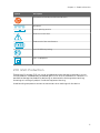
2.9
Symbols Used in AP10 Product Markings
Table 4 Symbols Used in AP10 Product Markings
Symbol Description
Meets the essential requirements of the applicable EC directives
Symbol of electrical and electronic equipment according to the WEEE
directive
FCC mark
AP10 User Guide M211860EN-C
16

Symbol Description
Environment Friendly Use Period of 10 years
DC power
Center polarity positive
Read user instructions
Trade mark of the manufacturer
Level VI eciency rating
Class II equipment
2.10 ESD Protection
Electrostatic Discharge (ESD) can cause immediate or latent damage to electronic circuits.
Vaisala products are adequately protected against ESD for their intended use. However, it is
possible to damage the product by delivering an electrostatic discharge when touching,
removing or inserting any objects inside the equipment housing.
Avoid touching component contacts or connectors when working with the device.
Chapter 2 – Product Overview
17

3. Installation
3.1 AP10 Installation Location and Range
In a typical indoor space, the wireless range of AP10 is at least 100 m (328 ft). In an open space
with line-of-sight and no interfering structures, the range can be over 500 m (1640 ft). Up to 8
access points can be placed within range of each other, even side-by-side, as long as they each
have their own VaiNet channel.
Walls and ceilings are good locations for AP10. Line of sight is not required. If possible, place
AP10 in the same floor as the data loggers. Point the antenna up or down for best wireless
performance.
Avoid placing AP10 close to large metal surfaces, as they may reduce the range of the radio
signal.
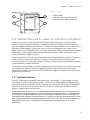
3.1.1 Mounting in Plenum Space
Plenum space is a separate air circulation space that is used by the building's heating and air
conditioning systems. For example, the space between the structural floor and the dropped
ceiling is typically used as an air-handling space. Due to fire safety considerations, the
materials placed in plenum space may be restricted by local legislation.
If you need to mount the access point in a plenum space but its materials do not meet your
local requirements, you can mount the access point inside a commercially available enclosure
that is meant for this purpose. For example, model 1075CP ceiling enclosure from Oberon
Wireless is suitable.
When selecting a plenum mounting enclosure, note the following requirements:
• The inside dimensions of the enclosure must be large enough for the access point. There
should be enough space to rotate the antenna if desired, and to easily connect the
cabling.
• The enclosure must not completely block the radio transmissions of the access point.
AP10 User Guide M211860EN-C
18
La pagina si sta caricando...
La pagina si sta caricando...
La pagina si sta caricando...
La pagina si sta caricando...
La pagina si sta caricando...
La pagina si sta caricando...
La pagina si sta caricando...
La pagina si sta caricando...
La pagina si sta caricando...
La pagina si sta caricando...
La pagina si sta caricando...
La pagina si sta caricando...
La pagina si sta caricando...
La pagina si sta caricando...
La pagina si sta caricando...
La pagina si sta caricando...
La pagina si sta caricando...
La pagina si sta caricando...
La pagina si sta caricando...
La pagina si sta caricando...
La pagina si sta caricando...
La pagina si sta caricando...
La pagina si sta caricando...
La pagina si sta caricando...
La pagina si sta caricando...
La pagina si sta caricando...
La pagina si sta caricando...
La pagina si sta caricando...
La pagina si sta caricando...
La pagina si sta caricando...
-
 1
1
-
 2
2
-
 3
3
-
 4
4
-
 5
5
-
 6
6
-
 7
7
-
 8
8
-
 9
9
-
 10
10
-
 11
11
-
 12
12
-
 13
13
-
 14
14
-
 15
15
-
 16
16
-
 17
17
-
 18
18
-
 19
19
-
 20
20
-
 21
21
-
 22
22
-
 23
23
-
 24
24
-
 25
25
-
 26
26
-
 27
27
-
 28
28
-
 29
29
-
 30
30
-
 31
31
-
 32
32
-
 33
33
-
 34
34
-
 35
35
-
 36
36
-
 37
37
-
 38
38
-
 39
39
-
 40
40
-
 41
41
-
 42
42
-
 43
43
-
 44
44
-
 45
45
-
 46
46
-
 47
47
-
 48
48
-
 49
49
-
 50
50


in altre lingue
- English: Vaisala AP10 User manual
Documenti correlati
Altri documenti
-
Dwyer Series DL6 Manuale utente
-
 Hach FL902 Basic User Manual
-
Dell W-Airwave Guida Rapida
-
TTS Log Box Guida utente
-
EINHELL Expert GE-LC 18/25 Li Set Manuale utente
-
-
ESAB LTR 200 Manuale utente
-
ESAB PT 23 Manuale utente
-
ESAB LTS 250 Manuale utente
-
ESAB LTN 160, LTN 200 Manuale utente
