
MAT244 User Manual
Programmable
RF Combiner
SN: ________________
rev.01 (ref. FW 1.7)
Date: 01 February 2018

MAT244 User Manual
rev.01
1
SAFETY INSTRUCTION
Read this safety instruction and the manual first
Follow all instructions and information.
Do not lose this manual.
Do not use this apparatus under the rain or near the water.
Do not install the apparatus near heaters or in hot environments, do not use outside the
operating temperature range.
Mount the apparatus as indicated in the instruction, do not block side grids for air ventilation
ATTENTION: supply the apparatus with a correct mains voltage and with the ground
connection. Check the power cord integrity.
The power cord must be protected from damage
Do not install the apparatus near heaters or in hot environments, do not use outside the
operating temperature range.
Do not open the apparatus, only qualified service technician are enabled to operate on it. The
apparatus needs servicing when it is not properly working or is damaged by liquids, moisture
or other objects are fallen in the apparatus.
Use only accessories or replacement parts authorized or specified by the manufacturer.
Clean the apparatus only with dry cloths, do not use liquids.
The ON/OFF is a double pole circuit breaker, but to ensure the complete disconnection of the
apparatus, disconnect the power cord.
Report the serial number and the purchasing date in front of the manual. It is needed to have
proper replacement parts or accessories from the manufacturer.
When replacement parts are needed, use only replacement parts authorized from the
manufacturer. Substitution with not authorized parts could result in electric shock, hazards or
fire.
Keep attention on all the labels with warnings or hazards on the apparatus.

MAT244 User Manual
rev.01
2
BRIEF DESCRIPTION
MAT244 is a programmable RF combiner, software configurable in:
Combiner 8:1 with 7dB max gain (not diversity)
Combiner 8:4 with 0dB max gain (not diversity)
Diversity Combiner 4:2 with 7dB max gain
MAIN TECHNICAL FEATURES
combiner 8:1 or 8:4 or 4:2 (sw configurable)
Wide bandwidth 150-840 MHz operation
Remote management and monitor of alarms thru Ethernet 10/100 base TX
Antenna booster on each inputs
Programmable attenuators on each inputs
Remote boost control (for gain/bandwidth) with a bidirectional data link thru coax (input
BNC’s)
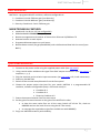
QUICK START INSTRUCTION
1. Connect to the power outlet using the supplied power cable (see rear panel)
2. Using coaxial cables withdraw the signal from BNC output connections (see rear panel: 4
outputs w, x, y, z)
3. Plug the antennas to the relative input connectors (see rear panel: A-B, 1 to 8 connectors)
4. Power on the MAT244
5. Switch off the unused areas/channels from the front panel
6. Choose the output option that best fits your needs. MAT244 is a programmable RF
combiner, software configurable (Setup > RF matrix menu) in:
Combiner 8:1
Combiner 8:4
Diversity Combiner 4:2
7. Power the antenna booster from the main menu
8. Set the gain of antenna booster or the gain of the MAT244 in order
to have the same noise floor on all the areas (switch off all the TXs, check on
MRK960 receiver the level of noise using the RF Test menu).
to coverage the required area (perform a Walk test with MRK960)
9. Enjoy our MAT244 versatility and reliability.

MAT244 User Manual
rev.01
3
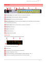
FRONT PANEL CONTROL AND FUNCTIONS
MAT244 allows an easy and quick configuration using buttons, push knobs and OLED display.
The front panel is functionally divided in the following section:
A – Lock/Unlock
To lock the MAT244 push the lock button in the front panel.
When the MAT is locked:
the circle led upper the lock button is yellow lighted
it is not possible to change any parameters on the status menu
it is not possible to enable/disable the RF input with the square button
B – Input Channels status
Gives you details about the 8 input antennas divided between channel A and channel B.
Here you can check RF status, antenna DC power and antenna attenuation.
C - LCD display
64 x 254 yellow-lighted display. 3 push buttons (membrane). The function of each button (upper,
middle and lower) will be readable from the context menu on the display.
D – Rotary Knob/Alarm indicator
Push rotary knob. Rotate and push to select. Warning (YELLOW) and Alarm (RED) light indicator
E – Matrix Leds
Link led shows the status of the host connection, Act the traffic and STA1/STA2 are the Ethernet
interface’s led.
F – Power AC
ON/OFF square powering button turns on/off the Matrix. When in OFF position both phases are
disconnected from power.
A
B
C
D
E
F

MAT244 User Manual
rev.01
4
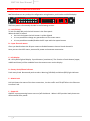
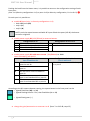
REAR PANEL
❶ ❷ ❸ ❹ ❺ ❻ ❼ ❽ ❾
❶ AC Power Plug AC mains power input, IEC Connector 90-264 Vac
❷ Product label with Serial Number, Options and Bandwidth
❸ Ground point To connect the rack to ground
❹ Label with IP address of Ethernet interface configured on the MAT244 (it can be modified
using the Manager application)
❺ Ethernet socket (RJ45) for connection to a network or computer
❻ Output W, X, channel A
❼ Output Y, Z channel B
❽ Input 1-4 channel A
❾ Input 1-4 channel B or 4-8
Status screen
After switch on, the matrix display the Status screen
❶ ❸ ❹
❷
❺
The main view has the following info:
❶ Device name
❷ main setting: RF, DC and attenuation parameters
❸ Channels 1-4 (diversity) or 1-8
❹ Setup menu (RF Matrix, antennas diagnosis, display brightness, info,…)
❺ RF bar menu to check the reception status of channels A and B

MAT244 User Manual
rev.01
5
Pushing the knob from the Status menu, it is possible to enter on the configuration setting of each
input port:
ports 1÷4 (diversity configuration 4->2) or ports 1÷8 (no diversity configuration, 8->1 or 8->2) ❷
For each port it is possible to:
enable RF input (only in diversity configuration 4->2)
o both A&B ports (AB)
o only A (A-)
o only B (-B)
NOTE: push the square button to disable RF input of both the ports (A & B): the button
becomes unlighted.
enable power supply DC (12V/250mA) to antenna booster
Configuration 4->2
Configuration 8->1 or 8->4
AB
DC enabled on both ports A&B
N
DC enabled
A-
DC enabled only on port A
-
no DC enabled
-B
DC enabled only on port B
--
no DC enabled
enable power supply DC with extra current (12V/800mA) ex. BAW
ONLY FOR PORT1 and PORT5
Configuration 4->2
Port 1a and Port 1b
Configuration 8->1 or 8->4
Port 1 and Port 5
HH
DC with extra current enabled on
ports 1a and 1b
H
DC with extra current enabled on port
1 or port 5
H-
DC with extra current enabled on
port 1a
-H
DC with extra current enabled on
port 1b
HB
DC with extra current enabled on
port 1a and standard DC on port 1b
AH
DC with extra current enabled on
port 1b and standard DC on port 1a
According to the DC antenna booster setting, the square button in the front panel can be
o lighted fixed blue (AB) or (N)
o lighted flashing blue for 5 sec, then fixed blue (A- or –B)
o lighted fixed green (--)
change the gain/attenuation on antenna A or B (from 7 to 24.5 dB, step 0.5)

MAT244 User Manual
rev.01
6
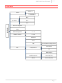
SETUP MENU
SETUP
Presets
User 1...9
Restore settings
FACTORY
RF MAtrix
8->1
8->4
4->2
Antennas diagnosis
Name
DISPLAY brightness 1 ÷ 15
DISPLAY timeout 5 ÷ 120
Info…
IP address
Serial
FW FW ver/Boot Ver/App FW ver
Temperatures
Main Board
RF
Supply diagnostic
Main RF (5V)
Main logic (5V)
Main PWR (12V) Alarms

MAT244 User Manual
rev.01
7
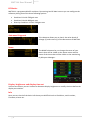
RF Matrix
MAT244 is a programmable RF combiner. By entering into RF Matrix menu you can configure the
software picking one of the three following options:
Combiner 8:1 with 7dB gain max
Combiner 8:4 with 0dB gain max
Diversity Combiner 4:2 with 7dB gain max
Antennas Diagnosis
This submenu allows you to check the value levels of
voltage (V) and current (I) of the 8 antennas of MAT244.
Name
The NAME submenu let you change the name of your
matrix that will be visible on the status menu and the
name of the Areas that will be visible on the monitoring
by Wisycom Manager:
Display brightness and display timeout
In these two menus you can increase or decrease display brightness or modify the time before the
display turns darker.
Info
Here you can check all the basic info about your MAT244 such as IP address, serial number,
Firmware, alarms etc.

MAT244 User Manual
rev.01
8
RF BAR MENU
It shows the current measured RF levels and the peak levels of areas.
RF level are wideband measurement and show the maximum power level measured from 150-
840MHz
Peak levels are reset whenever you go back to the RF BAR menu.
NOTE: 0 level corresponds to -20dBm (approx.. 85dBμV)
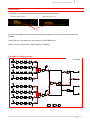
Example of configurations:
1
2
3
4
5
6
7
8
W
X
Y
Z
12V
12V
12V
12V
12V
12V
12V
12V
4*2
8*1
8*1
4*2
8*4
8*4
8*1
8*4
4*2
8*4
8*4
4*2
8*4
8*1
4*2
J1
B1
150MHz
B2
840MHz
R1
Step=0,5dB
Att_min=0dB
Att_max=31,5dB
B3
IN
B4
50
L1
J2
B6
150MHz
B7
840MHz
R3
Step=0,5dB
Att_mi n=0dB
Att_max=31,5dB
B8
50
L2
J3
B10
150MHz
B11
840MHz
R5
Step=0,5dB
Att_mi n=0dB
Att_max=31,5dB
B12
50
L3
J4
B14
150MHz
B15
840MHz
R7
Step=0,5dB
Att_mi n=0dB
Att_max=31,5dB
B16
50
L4
J5
B18
150MHz
B19
840MHz
R9
Step=0,5dB
Att_mi n=0dB
Att_max=31,5dB
B20
50
L5
J6
B22
150MHz
B23
840MHz
R11
Step=0,5dB
Att_min=0dB
Att_max=31,5dB
B24
50
L6
J7
B26
150MHz
B27
840MHz
R13
Step=0,5dB
Att_mi n=0dB
Att_max=31,5dB
B28
50
L7
J8
B30
150MHz
B31
840MHz
R15
Step=0,5dB
Att_mi n=0dB
Att_max=31,5dB
B32
50
L8
B34
PK-DET
B40
IN
B41
B42
PK-DET
B45
B46
B47
J9
J10
J11
J12
uC
B49
interface
Ethernet
B50
supply
Power
B51
0.23A/0.8A
0.23A
0.23A
0.23A
0.23A/0.8A
0.23A
0.23A
0.23A
Config 8:1
peak levels
diversity configuration 4->2
configuration 8->1 or 8->4

MAT244 User Manual
rev.01
9
1
2
3
4
5
6
7
8
W
X
Y
Z
12V
12V
12V
12V
12V
12V
12V
12V
4*2
8*1
8*1
4*2
8*4
8*4
8*1
8*4
4*2
8*4
8*4
4*2
8*4
8*1
4*2
J1
B1
150MHz
B2
840MHz
R1
Step=0,5dB
Att_min=0dB
Att_max=31,5dB
B3
IN
B4
50
L1
J2
B6
150MHz
B7
840MHz
R3
Step=0,5dB
Att_mi n=0dB
Att_max=31,5dB
B8
50
L2
J3
B10
150MHz
B11
840MHz
R5
Step=0,5dB
Att_mi n=0dB
Att_max=31,5dB
B12
50
L3
J4
B14
150MHz
B15
840MHz
R7
Step=0,5dB
Att_mi n=0dB
Att_max=31,5dB
B16
50
L4
J5
B18
150MHz
B19
840MHz
R9
Step=0,5dB
Att_mi n=0dB
Att_max=31,5dB
B20
50
L5
J6
B22
150MHz
B23
840MHz
R11
Step=0,5dB
Att_min=0dB
Att_max=31,5dB
B24
50
L6
J7
B26
150MHz
B27
840MHz
R13
Step=0,5dB
Att_mi n=0dB
Att_max=31,5dB
B28
50
L7
J8
B30
150MHz
B31
840MHz
R15
Step=0,5dB
Att_mi n=0dB
Att_max=31,5dB
B32
50
L8
B34
PK-DET
B40
IN
B41
B42
PK-DET
B45
B46
B47
J9
J10
J11
J12
uC
B49
interface
Ethernet
B50
supply
Power
B51
0.23A/0.8A
0.23A
0.23A
0.23A
0.23A/0.8A
0.23A
0.23A
0.23A
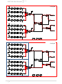
Config 4:2
Config 8:4
inputs A
inputs B

MAT244 User Manual
rev.01
10
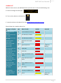
ALARM LIST
When an alarm occurs, the MAT244 advises you with one or more of the following acts:
A. Show a message on the display
B. Turn on the yellow or red alarm led
C. Insert the alarm on the alarm list in the MAIN>Options>Info>Alarms menu
Shown below the complete alarms list:
Message on display
(A)
Type
Alarm List (C)
Led (B)
Aux Led
Invalid Calibration
Memory
Gen
Invalid calibration memory
Fixed Red
---
Calibration data copy
#1 invalid
Gen
Cal. Data copy 1 invalid
Fixed Yellow
---
Calibration data copy
#2 invalid
Gen
Cal. Data copy 2 invalid
Fixed Yellow
---
Calibration data
copies differ
Gen
Calibration data copies
differ
Fixed Red
---
System boot failed
Gen
---
Fixed Red
---
Internal high
temperature
Gen
High temperature
Fixed Red
TEMP Fast
Blinking
Communication error
on I2C bus #0
Gen
I2C bus #0
Fixed Red
---
Communication error
on I2C bus #1
Gen
I2C bus #1
Fixed Red
---
Temperature main
board sensor doesn't
communicate
Gen
Temp. main board sensor
comm.
Slow Blinking Red
---
Temperature RxA
board sensor doesn't
communicate
Gen
Temp. RxA board sensor
comm.
Slow Blinking Red
---
Temperature RxB
board sensor doesn't
communicate
Gen
Temp. RxB board sensor
comm.
Slow Blinking Red
---
Eth rx busy
Gen
Eth rx busy
Fixed Red
---
Error updating
calibration copy crc
Gen
Cal copy crc update error
Fixed Red
---
Fan #1 does't work
properly
Gen
Fan #1
Fixed Yellow
FAN1 Fast
blinking

MAT244 User Manual
rev.01
11
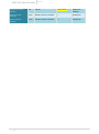
Fan #2 does't work
properly
Gen
Fan #2
Fixed Yellow
FAN2 Fast
blinking
Antenna nA: DC
overload
Anten
Antenna nA: DC overload
---
Antenna N
Antenna nB: DC
overload
Anten
Antenna nB: DC overload
---
Antenna N

MAT244 User Manual
rev.01
12
TECHNICAL SPECIFICATION
Power supply
:
AC connector 90÷264Vac / T2A, 47÷63Hz
Working frequency
:
150 ÷ 840 MHz
Amplifier linearity
:
± 1 dB (typical)
“A” / “B” antenna
input
:
8 BNC type connector
antenna output
:
4 BNC type connector
Impedance
50 Ω
Input/output Gain
:
7 dB (combiner 8:1), OIP3=30dBm typ.
0 dB (combiner 8:4), OIP3=24dBm typ.
7 dB (diversity combiners 4:2), OIP3=30dBm typ
Noise Figure
5.5dB (each channel)
Antenna booster
powering
:
+12Vcc / 800mA MAX.(ports 1a, 1b)
+12Vcc / 230mA MAX.(other ports)
Configuration/monitor
interfaces
:
10/100 Base TX Ethernet port
Display
:
64 x 256 OLED (yellow)
Dimension
:
Standard rack (aluminum) 19” / 1U.
Weight
:
3,7 Kg
Type approvals
In compliance with
EN 301 489-1/-9
EN 600065
EN 300 422-1/-2
47 CFR 15 Subpart B
Statements regarding FCC and Industry Canada
This device complies with part 15 of the FCC Rules and RSS-210 of Industry Canada. Operation is subject to the following two
conditions:
(1) This device may not cause harmful interference, and
(2) This device must accept any interference received, including interference that may cause undesired operation.
In compliance with
47 CFR 15 Subpart B
CAN RSS-Gen/CNR-Gen
ENVIRONMENTAL INFORMATION
Applicable in the European Union and other European countries with separate collection systems

MAT244 User Manual
rev.01
13
Disposal of Old Electrical & Electronic Equipment (2002/96/EC)
This symbol indicates that this products shall not be treated as household waste. Instead it shall be
handed over to the appropriate collection point for the recycling of electrical and electronic equipment.
The recycling of material will help to conserve natural resources.
ITALY ONLY
Obblighi di informazione agli utilizzatori
ai sensi dell’art. 13 del Decreto Legislativo 25 luglio 2005, n. 151 “Attuazione delle Direttive 2002/95/CE, 2002/96/CE e
2003/108/CE, relative alla riduzione dell’uso di sostanze pericolose nelle apparecchiature elettriche ed elettroniche, nonché
allo smaltimento dei rifiuti”
Smaltimento di apparecchiature elettriche ed elettroniche di tipo professionale
Il simbolo del cassonetto barrato riportato sull’apparecchiatura o sulla sua confezione indica che il prodotto
alla fine della propria vita utile deve essere raccolto separatamente dagli altri rifiuti.
La raccolta differenziata della presente apparecchiatura giunta a fine vita è organizzata e gestita dal
produttore. L’utente che vorrà disfarsi della presente apparecchiatura dovrà quindi contattare il produttore e
seguire il sistema che questo ha adottato per consentire la raccolta separata dell’apparecchiatura giunta a fine
vita.
L’adeguata raccolta differenziata per l’avvio successivo dell’apparecchiatura dismessa al riciclaggio, al trattamento e allo
smaltimento ambientalmente compatibile contribuisce ad evitare possibili effetti negativi sull’ambiente e sulla salute e
favorisce il reimpiego e/o riciclo dei materiali di cui è composta l’apparecchiatura.
Lo smaltimento abusivo del prodotto da parte del detentore comporta l’applicazione delle sanzioni amministrative previste
dalla normativa vigente.
Iscrizione al Registro A.E.E. n. IT09100000006319

MAT244 User Manual
rev.01
14

-
 1
1
-
 2
2
-
 3
3
-
 4
4
-
 5
5
-
 6
6
-
 7
7
-
 8
8
-
 9
9
-
 10
10
-
 11
11
-
 12
12
-
 13
13
-
 14
14
-
 15
15
-
 16
16


