WisyCom MCR41S-42S Manuale utente
- Categoria
- Attrezzatura musicale
- Tipo
- Manuale utente

Single-Dual True Diversity
Camera Receiver
SN: ________________
rev.14 (rif. FW 3.21)
Date: 25 June 2018
MCR41/MCR42 User Manual

MCR41/MCR42 User Manual
1
BRIEF DESCRIPTION
MCR41/42 is a high performance microphone receiver suitable for broadcast and high
professional applications.
Thanks to Wisycom movable filter technology, MCR42 is able to work in a bandwidth up to 230
MHz, still keeping an exceptional selectivity and intermodulation immunity.
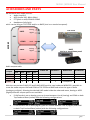
This miniature design allows to integrate a DUAL TRUE DIVERSITY receiver while keeping a small
size to fit camera slot in:
Ikegami/Panasonic (UNISLOT™)
Philips/Thomson/Grass Valley
Sony
Quad Pack & Six Pack
The audio receiver block is fully digital to allow a better quality, digital output and emulation of
most of companding chipsets. It supports also AES3 audio output with an overall sounds delay
below 1.5 msec.
MCR42 is designed to be:
“easy & quick to use” thanks to automatic setup functions (i.e. frequencies, squelch,
scan), remote configuration utilities (thru infrared), an OLED display with intuitive
context menu navigation.
“extremely flexible”, with an incredible frequency agility up to 230MHz. Moreover the
DSP board allows analogue and digital (AES3) output, with multi-companding
compatibilities and other digital features.
“best in class performances”, thanks to the latest Wisycom technology the unit has
extreme RF sensitivity and immunity and superb audio quality.
“a durable & upgradable investment”, thanks to the very robust design (aluminium
housing) and the possibility to upgrade/enhance units performances.
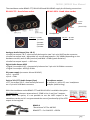
Moreover MCR42 system is already set up for the exclusive PTT function (remote command),
developed and patented by Wisycom and now appreciated in the broadcast world:
Simply pushing this button (PTT), the presenter causes the remote switching of the receiver’s
output-line, from the “main line” to the additional “intercom line”, in order to be able to talk “off-
air” directly with the technical team. Then all PTT’s MICs can be connected in pre-fading allowing a
clever intercom setup.

MCR41/MCR42 User Manual
2
SAFETY INSTRUCTION
Read this safety instruction and the manual first
Follow all instructions and information.
Do not lose this manual.
Do not use this apparatus under the rain or near the water.
Do not install the apparatus near heaters or in hot environments, do not use outside the
operating temperature range.
Do not open the apparatus, only qualified service technician are enabled to operate on it. The
apparatus needs servicing when it is not properly working or is damaged by liquids, moisture
or other objects are fallen in the apparatus.
Use only accessories or replacement parts authorized or specified by the manufacturer.
Clean the apparatus only with dry cloths, do not use liquids.
Report the serial number and the purchasing date in front of the manual. It is needed to have
proper replacement parts or accessories from the manufacturer.
When replacement parts are needed, use only replacement parts authorized from the
manufacturer. Substitution with not authorized parts could result in electric shock, hazards or
fire.
Keep attention on all the labels with warnings or hazards on the apparatus.
WARNING: The apparatus is intended for professional use; anyway the manufacturer alerts the
user that the headphone output power of the apparatus could exceed the level of 85 dB(A) of
sound pressure level and this could be dangerous for the hearings. Do not use the headphone with
high power level or for long time. Reduce the power or suspend the hearing in case of any kind of
hearing problem.
WARNING: when operating thru battery pack always replace ALL BATTERIES.
DO NOT operate the device with some new and some old batteries.
When MCR42 is setup to “automatically turn on”, DO CHANGE ALL OF USED BATTERIES after
automatic low batteries shutdown.

MCR41/MCR42 User Manual
3
MAIN FEATURES
MCR41/42(*) is a camera dual true diversity wireless-microphone receiver system in a modular
stand-alone or slot-in configuration (compatible with most camera’s slot):
Extreme RF (radiofrequency) performances and reliability
Extreme frequency agility (tuning windows up to 240 MHz with independent tunable
filters on 2 ch’s):
- MCR42-N 470÷700 MHz
- MCR42-M: 566÷798 MHz
- MCR42-L: 470÷678 MHz
- MCR42-H:590÷822 MHz
(extended range up to 830 available on request and upon your country-specific
regulations)
digital output on AES3
multi-companding compatibility
40 groups of 60 channels fully user
programmable (2400 frequencies!!)
future digital functionality enhancements
Automatic scan for best channels, squelch and other automatic setup
Infrared interface (i.e. for system setup, microphone programming)
Automatic transmitter re-programming (thru infrared, sync function)
Push to Talk (PTT) function with additional audio output signals (patented)
(*) Note MCR41 is the version with only one diversity RX board mounted. It supports all features of
MCR42 and is compatible with MCR42 Firmware.
It is also possible to mount the second Rx board to upgrade a MCR41 to an MCR42.
Technical description
The MCR42 is a professional dual true diversity receiver for wireless microphones reception
especially designed for broadcast production, live stages, theatres and top professional
applications.
It’s winning performances are:
High immunity on strong RF environment
Huge switching bandwidth
High audio performances and flexibility with analog or digital processors
High reliability and durability
One of the milestones in the design of the MCR42 is high reliability: most of the circuitry of the
receiver is independent one from each other.
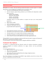
40 Groups
60 Channels

MCR41/MCR42 User Manual
4
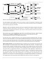
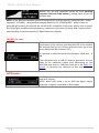
Above a schematic with an overview of main receiver functions.
For each antenna the RF signal is split in the receiver 1 and in the receiver 2 (antenna A and
antenna B) with a wide band splitter. In this way any one receiver could be tuned in any frequency
of the switching range (typ. 240 MHz).
Receiver 1 and 2 are diversity receivers: each one is made of two receivers tuned on the same
frequency, hereafter called section A and section B. The receiver 1 section A and the receiver 2
section A are connected to the antenna A, the receiver 1 section B and the receiver 2 section B are
connected at the antenna B.
Each receiver has its own demodulated signal and its own RSSI signal (Receiver Signal Strength
Indication); a DSP selects or combines signals from section A & B to have the best audio.
The demodulated signal flows to the digital audio processor.
the data sub carrier is digitally filtered to a very selective equivalent bandwidth (3Hz). Each filter
has its own data demodulator, one for medium speed data detection at the output of the first filter
and one at low speed data detection at the output of the second filter. All the two demodulators
are connected to the supervisor micro controller for the data battery detection and signalling.
Digital audio processor: the demodulated signal is filtered by an anti aliasing low pass filter and
then converted in the digital domain with a 96KHz 24bit audio A/D converter. The digital signal
processor (DSP), working in double precision, replicates all the analog functions with very high
accuracy, ultra low distortion and without typical analog problems like components tolerances or
long term drifts or temperature drifts etc. The high speed audio algorithms implemented in
assembler into the MCR42 maintains the audio delay at about 1.3 milliseconds, making it ideally
for live events and to keep audio delay as short as possible. The DSP unit also filters and
demodulates the data carrier and communicates all the parameters and informations to the
supervisor micro controller. The audio output goes to the digital outputs (AES3) or is converted in
the analog domain with a high quality 24 bits 96KHz D/A converter and an anti-aliasing filter.
Receiver -1-A
Receiver -1-B
Receiver -2-A
Receiver -2-B
TrueDiversity
Control Rx1
True Diversity
ControlRx2
Communic.
and control
interface
Receiver supervisor
microcontroller
and userinterface
Front panel
Digital
output
A
B
Antennainputs
Line1
Line2
ComRx1
ComRx2
INFRARED
SERIALLINK
Analogue
output
PTT
output
Ear-ph Left
Ear-ph Right
Ear-
phone

MCR41/MCR42 User Manual
5
USER GUIDE
NEW DISPLAY
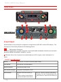
Front Panel
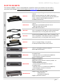
MCR42 allows an easy and quick configuration using buttons, RGB LED’s and an OLED display. The
front panel is functionally divided in the following section:
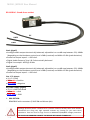
A & B SMA antenna Connector:
MCR42 is supplied with a couple of antenna tuned on 400 MHz bandwidth suitable to be used with
MCR42-N, MCR42-M, MCR42-L, MCR42-H version.
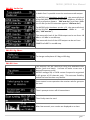
C RGB Leds: Each of the 2 receivers has a dedicated set of LED’s to give a clear indication of its
status.
“ON LED” (on NEW display)
GREEN
The receiver is on with an external power supply
PALE GREEN
The receiver is on with battery
GREEN BLINKING
The external power is low
PALE GREEN BLINKING
The power of the battery is low
RED BLINKING
Relative transmitter battery is
low:
- slowly blinking if 25% lifetime
- quickly blinking if 12% lifetime
When the “ON LED” become red blinking,
the display, if it is off, it automatically turns
on and remains on until the alarm does not
fall.
A
C
C
B
C
D
E
F
G

MCR41/MCR42 User Manual
6
“ON LED” (on OLD display)
OFF
Relative receiver is not active
GREEN
Relative receiver is active and battery/external power is not low
RED
Relative receiver is active and battery/external power is low
RED BLINKING
Relative transmitter battery is low:
- slowly blinking if 25% lifetime
- quickly blinking if 12% lifetime
“RF LED”
OFF
Relative receiver is not active
RED
RF level below squelch on both diversity receivers
GREEN
RF level above squelch and receiver A is active (ANTENNA A)
BLUE
RF level above squelch and receiver B is active (ANTENNA B)
“AUDIO/AF LED”
RED
Audio muted due to RF squelch or tone squelch
GREEN
Audio active & tone squelch detected
BLUE
Audio active & tone squelch not detected (or when calibration tone is active)
D “MENU/SEL” BUTTON
Push this button to navigate function menu’s and to confirm the chosen setup.
F “PWR/EXIT” BUTTON
Push and keep this button to power on/off the receiver. The on/off status is permanently
memorized into the non-volatile memory, this way the system can be setup to automatically turn
on Rx1, or Rx2, or both, when power up.
During menu navigation push this button to exit from current menu (escape function).
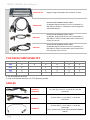
E “Arrow up/sync” BUTTON
Push and keep this button to start a synchronization with a Wisycom transmitter (follow instructions
on display). Before starting synchronization IRDA must be enabled on Wisycom transmitter.
During menu navigation push this button to move -up and select the previous item.
G “Arrow down/scan” BUTTON
Push and keep this button to start the automatic scan.
During menu navigation push this button to move-down and select the previous item.
H “OLED Display”
The receiver has a high contrast display. Pushing a button while the receiver is active, turn on
automatically the display. After a time-out the display turns off automatically.

MCR41/MCR42 User Manual
7
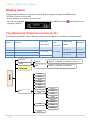
Display menu
Using navigation buttons it is possible to quick & easy navigate through the MCR42 menu:
- SEL/Exit to enter or exit a level
- Arrow up/down to circle on the same level
- To save the modified parameters press and hold the SEL /MENU button ( ) until appears the
message "SAVED!".
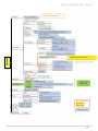
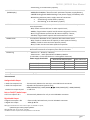
Tree Menu (ref. firmware version v3.21)
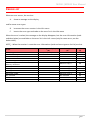
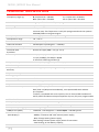
According to the MCR42 model, different audio levels (analogue) are available (see below table).
Model
Features
Max audio
level (anal.)
SND/D
ratio
(Analogue)
SND/D ratio
(AES3)
Distortion
MCR42
first hardware
-18÷12dBu
110 dB typ.
125 dB typ.
0.3 % typ
MCR42S
new main and new display
-30÷12dBu
MCR42S2
new Rx
140 dB typ.
0.1 % typ.
MCR42S3
new main,top feed configuration
-30÷18dBu
MAIN
Infrared
Preset
Restore PRESET_1 / PRESET_2 / PRESET_3 / Factory
Save PRESET_1 / PRESET_2 / PRESET_3
Advanced
Info
Power
Model
Serial
Range
Base
Alim
FW
Version
BL
App
DSP
HW
HW rev
Options
Top
Display
Errors

MCR41/MCR42 User Manual
8
Advanced

MCR41/MCR42 User Manual
9
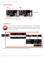
STATUS MENU
Quick Menu
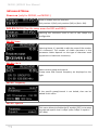
From FW version 3.0, pushing “Arrow down/scan” button or “Arrow up/sync”
button, it’s possible to enter in a circular menu where you can see the main
parameters of the receiver as frequency, group, channel, Expander, RF level,
squelch and audio level.
The screens of the circular menu are described in the following table
Status Screen
RX1
RX2
Group
Channel
RF bar
(8 steps of 10dBµV,
from 10 to 80 dBµV)
Squelch Level
Frequency
TX battery
Level
Modulation bar
(from -42 to 0 dB)
Peak deviation ≥
56KHz
By name
By Ch/Gr

MCR41/MCR42 User Manual
10
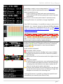
Depending on what is set on the parameter “Fast ch sel” in the
Main menu, in the first and second screen of the circular
menu it’s possible to see:
- N° RX, Frequency, group (and name) and channel or
- N° RX, Name of the channel, group (and name), Expander
and channel
of receiver 1 (first screen) and receiver 2 (second screen)
Pushing SEL button it’s possible to change freq/GR/CH.
From FW 3.0 and above, it’s possible to assign a name and an
Expander to a channel using the Wisycom MCR4x Manager
v.1.0.1 or above (to understand how to do it, read How to
assign a name and an expander to a channel on the Wisycom
MCR4x Manager guide)
Note: It’s not possible to change name and expander of a channel
from the device (only from Wisycom MCR4x Manager)
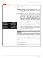
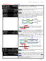
In the third screen are showed the instant RF levels of the two
receivers (❸,❹) and it is showed the minimum, maximum
and average value calculated in a time frame of about 4
minutes (❻,❼).
In this screen are showed:
❶ the number of the receiver
❷ an indication bar from 0 to 70 dBµV with step of 10dBµV
❸ two bars that indicate the RF level on antenna A (above)
and B (below)
❹ the current RF level of the antenna with the highest level in
dBµV
❺ the level of squelch
❻ an indication bar to see the min, max and average RF level
in the recorded time (about 4 minutes). At the end of the
recording time, the indication bar stop to update the RF
levels (it can be used to make a walk test).
❼ a time bar that indicates the recording time of the RF level.
On the left of the time bar there is a blinking triangle that
disappear at the end of the recording time.
Pushing SEL button it’s possible to change the squelch level
automatically or manually (one RX at a time).
❼
❸
❹
❺
❹
❺
❸
❷
❻
❻
❶
❶
By name
By name
By Ch/Gr
By Ch/Gr

MCR41/MCR42 User Manual
11
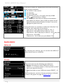
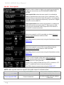
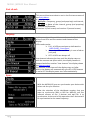
In the fourth screen are displayed the main audio information
In this screen are showed:
❶ the number of the receiver
❷ the Expander
❸ the max audio level
❹ an indication bar from -42 to 0 dB with step of 6dB
(0dB peak deviation ≥ 56KHz)
❺ the modulation level with the indicator of modulation
peak (when the indicator goes to 0dB, the square on the
right of the display become white for about 1 second to
highlight the peak occurred)
Pushing SEL button it’s possible to enable the Calibration Tone
and set the max audio level of the outputs:
- LINE max lev: -8÷12 dBu (only for HW rev ≥ 21)
- MIC max lev: -30÷10 dBu (only for HW rev ≥ 21)
- LINE max lev: -18÷12 dBu (only for HW rev < 21)
- AES max lev: -30÷0 dBFS
- COM max lev: -18÷12 dBu (only with BPA42-PTT)
MAIN MENU
Infrared:
By activating the infrared, you can connect the MCR42 to
other devices (such as a UPK300)
Preset:
The preset menu has the following two submenus:
Restore: that allows to reload 3 different presets
(PRESET_1, 2, 3) earlier saved or a Factory preset (a preset
load in the Wisycom factory)
Save: that allows to save 3 different presets (PRESET_ 1, 2,
3)
Each saved preset consists of all user parameters indicated
in blue in the graphic on page 8 (Display menu).
❶
❷
❸
❹
❺
❶
❷
❸
❺
Step 1dB

MCR41/MCR42 User Manual
12
Advanced:
Select Advanced menu to access to other advanced
parameters
Info
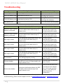
In the info menu the following information are displayed:
Info
description
example
Power:
Supply voltage measured
12.0Volt
Model:
MCR42 dual rx / MCR41
MCR42 dual rx
Serial:
The serial number composed by 1 letter+7 numbers
S3536539
Range:
Frequency range according to the MCR band:
L: 470-678
H: 590-822
N: 470-700
M: 566-798
470-678
Base:
Version of rear panel:
BPA42-PTT/HPN/BAG
S1LK 42-SX
SLK 42-IK
SLK 42-PH
BPA42-HPN
Alim:
Type of power supply
Ext
FW:
Version:
FW version
v2.0.5
BL:
Bootloader version
v.1.0.18
App:
Application version
v2.5d
DSP:
DSP version
v0.0.55r
HW:
HW rev:
Hardware version
21
Options:
For this product the option specific the band (L/H/N/M)
L
Top:
Indicates if there is mounted a Top Feed and the type
EL2
Display
0 if there is an old display / 1 if there is a new display
1
Errors:
Number of errors.
If the number of errors is > 0 push SEL button to enter on the Errors list.
For each error a brief description and the error code is showed.
For more information, please see the Error List section.
0

MCR41/MCR42 User Manual
13
Advanced Menu
Power on (only for MCR42, not MCR41)
Allow to enable both the receivers:
Only receiver 1 (Rx1), only receiver (Rx2) or (Rx1 + Rx2).
Edit RX (MCR42 has the same menu for RX1 and RX2)
Selecting this sub-menu most of RX1 or RX2 setups are
configurable.
Edit RX: Name
Selecting Name, it’s possible to edit the name of the receiver
(12 characters). The number of visible characters in the
parameter Name depends on the type of characters used
(uppercase or lowercase characters).
Edit RX: GR-Ch
Select current group and channel.
Group name and channel frequency are displayed on the
right.
Edit RX: Frequency
If the specific group/channel is not locked, then can be
edited in this menu.
Edit RX: Squelch
This menu allows to disable the RF squelch (OFF) or to setup
the desired squelch level in dBµV (note 0 dBµV is equal to -
107 dBm).

MCR41/MCR42 User Manual
14
Edit RX: Expander
MCR41/42 supports 4 different type of “Expanding systems”
(other on request)
ENR-Wisy: designed for maximum noise reduction
ENC-Wisy: designed for maximum audio fidelity (use this in
case of special vocal application or to remote
instruments)
ENR-1.2*/ENC-1.2*: to use MCR42 with some type of
camera (ex. Canon® C300, Canon® XF305, Sony®
Pmw200, Sony® Pmw300, Sony® PmwF5, Sony® Fs7,
Nikon® D600 or Nikon® D800, Canon® SD mark3...)
which accept a signal with reduced dynamic. This
type of expansion doesn't add artifacts to the signal
and allows to have a less noisy signal. It allows to
improve the quality of the audio registration
(compared to the ENR/ENC standard) increasing the
S/N ratio up to 15dB.
To use these expanders, it’s necessary to set ENR on
the transmitter and ENR 1.2 on the receiver or set
ENC on the transmitter and ENC 1.2 on the receiver.
ENR-1.2 it’s used for the optimization of noise, ENC-
1.2 it’s used to optimize the voice.
NB: The compander of the receiver must be the same as the
transmitter
MCR42 core is a power digital audio processor that, besides
an unbeatable audio quality and flexibility, can emulate
most expanders systems on the market. On this menu you
can setup the audio expanding chipset emulation. ENR is
emulating the Philips™ SA572 and PTT digital data of
Wisycom transmitters. Other setups can be loaded on
request.
*Available only from FW v3.3
Canon is a trademark of Canon Incorporated, Nikon is a trademark of Nikon Corp,
Sony is a trademark of Sony Corp.

MCR41/MCR42 User Manual
15
Edit RX: Tone Squelch
MCR42 is able to detect a digital tone squelch generated by
a Wisycom transmitters (ex. MTH400/MTH300/MTP40/
MTP30).
Tone squelch ON: when the tone squelch is enabled the
audio is muted unless the correct carrier is detected. Tone
squelch allows to work with lower RF squelch, increasing the
coverage and the robustness especially in presence of digital
television carriers (DVB-T).
Tone squelch ADVanced: when tone squelch is in advanced
mode the receiver processes also PTT data (push to talk):
activating the command audio output when the button is
pressed on remote transmitter.
When tone squelch is off it is possible to choose where to
put the output between LINE and COM.
The COM column is present only using the Stand alone socket
BPA42-PTT
When tone squelch is set to ON it is possible to choose
where to put the output between LINE and COM.
The COM column is present only using the Stand alone socket
BPA42-PTT
When tone squelch is in advanced mode it is possible to
access a more complex audio matrix where to put the
output between LINE and COM and between PTT rel.
(released) and PTT psh (pushed)
Usually Line is always ticked and Com (PTT) is ticked on “PTT
push.” as additional return channel (intercom).
The COM column is present only using the BPA42-PTT
NOTE: With squelch and tone squelch the audio output is activate when:
Squelch OFF
Squelch = 0,3,6,… dBµV
Tone squelch OFF
Always
RF level ≥ Squelch
Tone squelch ON
If tone is detected
RF level ≥ Squelch & tone squelch
is detected

MCR41/MCR42 User Manual
16
Edit RX: Audio Out
In Audio Out it’s possible to set the maximum audio output.
For MCR42 with Hardware version ≥ 21, the max audio level
of the RX1/RX2 output can be set from -30dBu to -10 dBu (in
the first selection appears “MIC max lev”) and from -8dBu
to +12 dBu (in the first selection appears “LINE max lev”)
For MCR42 with Hardware version < 21, the max audio level
of the RX1/RX2 output can be set from -18dBu to -12
dBu (“LINE max lev”)
The max audio level of the COM output can be set from -18
dBu to +12 dBu in one dB step.
The max audio level of the AES3 output can be set from -
30dBFS to 0 dBFS in one dB step.
Edit RX: Sig. Phase
To change audio phase of 0 deg or 180 deg.
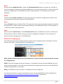
Edit RX: Scan
This function can be called also using the dedicated scan
button (push and keep). It allows to make a scan over a
desired frequency group.
MCR42 manages up to 2400 custom frequencies organized
in 40 groups of 60 channels each. This extreme flexibility
makes the scan function very flexible.
Once started a scan operation the receiver asks for group to
be used.
Then it prompts to turn off all transmitters.
Then finally start the scan!
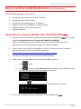
After few seconds, scan results are displayed on a chart.

MCR41/MCR42 User Manual
17
Results can be also displayed sorted by level (pushing
together SYNC and SCAN buttons), making easier to pick up
the best one.
NOTE: As per Wisycom standard, group 00 and group 01 or 09 are special; respectively the “center
frequency” (474,482/... MHz) and the intergap frequency (i.e. 470/478/486/... MHz). A scan on
group 00 will reveal in few seconds the overall DVB-T occupation on the area, while a scan on group
0 or 09 will give possible working frequency, usable also in presence of strong DVB-T signal (sort to
speak working in the band-guard of 2 digital television channel).
Edit RX: Cal. tone
If Cal. tone is enabled, a calibration tone is transmitted from
the outputs of the receiver and the audio LED of the relative
RX become blue (to turn off the calibration tone, go on the
menu Advanced > RX and press EXIT)
It’s possible to select the audio level between -18dB and 0
dB.
The calibration tone at 0dB it’s used to generate a tone at
1KHz at the maximum output level (depending on the
MIC/LINE max level or COM max level set in the Audio out
menu). It represent the reference of the peak deviation
(56KHz).
LINE mode:
In LINE mode is settable the type of output between analog
and AES3 (digital).
NOTE: When LINE mode is set to AES3 the digital output
(Rx1+Rx2 in digital) is available on Rx1 output.

MCR41/MCR42 User Manual
18
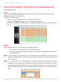
Headphones (only for BPA42-HPN)
Cycle through menu’s with up/down arrow to get your
desired configuration then confirm with SEL.
Volume: It is possible to set the desired output level from
Max (+6 dB) to min (-24 dB) in 1 dB step.
Balance: with this parameter it’s possible to balance the
delta of the volume between Left and Right on the
headphones (it’s possible to set up to 12dB between L/R).
For example: if volume is set to 0dB and Balance to R+4, in
the HP output, L will be -2dB and R will be 2dB.
RX mix: if the parameter RX sel is set to Rx1+Rx2(L+R), it’s
possible to balance the delta of the volume between RX1
and RX2 (it’s possible to set up to 12dB between RX1/RX2).
For example: if volume is set to 0dB, Rx signal to
Rx1+Rx2(L+R) and RX mix to Rx1+6, in the HP output, RX1
will be at 3dB and RX2 will be at -3dB.
RX sel: Left and right channel of stereo jack can be mapped
respectively on RX1, RX2 or on RX1+RX2.
Signal: If set to LINE, on the headphones there is the same
signal of the output LINE. If set to TSQ>LINE and the Tone
Squelch is enable (Tone Squelch ON or ADV), on the
headphones it is possible to hear the signal even when the
Tone Squelch is not detected.
Example: if Volume= 0dB & Balance= R+4
RX1
RX2
DSP
L=-2dB
R=2dB
Δ=4dB
0dB
2dB
-2dB
Delta is centered on the set
Volume (in this case 0dB)
L
R
0dB
3dB
-3dB
Delta is centered on the set
Volume (in this case 0dB)
RX2
RX1
(RX1@3dB)+(RX2@-3dB)
(RX1@3dB)+(RX2@-3dB)
RX1
RX2
DSP
Example: if Volume=0dB, RX sel= Rx1+Rx2(L+R) & RX mix= Rx1+6
+
L
R
Δ=6dB
Δ=6dB

MCR41/MCR42 User Manual
19
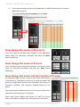
Fast ch sel:
This menu allow to set what to see in the first two screens of
the Quick Menu.
It’s possible to set:
- By Ch/Gr = Frequency, group (and propriety) and channel;
- By name = Name of the channel, group (and propriety)
channel and Expander.
of receiver 1 (first screen) and receiver 2 (second screen)
Display:
In this menu item it’s possible to set the mode of switch on
of the front LEDs and the contrast and timeout of the
display.
LEDs mode can be:
Full: all LEDs are activate as indicated on
-USER GUIDE - Front Panel
Alarm: the LEDs are ON only in case of alarm
(only red)
OFF: all LEDs are always off
Low timeout indicates the time until the display stays on
with the contrast set (after which, the display contrast is
lowered and after another “Low timeout” the display shows
the Status screen).
Off timeout is the time until the display stays on (after
which, the display will automatically turn off). If Off timeout
is set to OFF the display never turn off automatically.
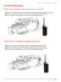
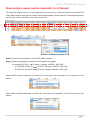
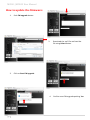
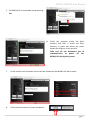
Sync:
With the MCR41/42 you can synchronize your device with
others via the sync function.
After the selection of the desiderate receiver that you
want to synchronize (RX1 or RX2 for MCR42), pull the
infrared sensors of the 2 devices and wait for it to
synchronize. At the end of this operation the 2 devices will
be synchronized to the same frequency.
La pagina sta caricando ...
La pagina sta caricando ...
La pagina sta caricando ...
La pagina sta caricando ...
La pagina sta caricando ...
La pagina sta caricando ...
La pagina sta caricando ...
La pagina sta caricando ...
La pagina sta caricando ...
La pagina sta caricando ...
La pagina sta caricando ...
La pagina sta caricando ...
La pagina sta caricando ...
La pagina sta caricando ...
La pagina sta caricando ...
La pagina sta caricando ...
La pagina sta caricando ...
La pagina sta caricando ...
La pagina sta caricando ...
La pagina sta caricando ...
La pagina sta caricando ...
La pagina sta caricando ...
La pagina sta caricando ...
La pagina sta caricando ...
-
 1
1
-
 2
2
-
 3
3
-
 4
4
-
 5
5
-
 6
6
-
 7
7
-
 8
8
-
 9
9
-
 10
10
-
 11
11
-
 12
12
-
 13
13
-
 14
14
-
 15
15
-
 16
16
-
 17
17
-
 18
18
-
 19
19
-
 20
20
-
 21
21
-
 22
22
-
 23
23
-
 24
24
-
 25
25
-
 26
26
-
 27
27
-
 28
28
-
 29
29
-
 30
30
-
 31
31
-
 32
32
-
 33
33
-
 34
34
-
 35
35
-
 36
36
-
 37
37
-
 38
38
-
 39
39
-
 40
40
-
 41
41
-
 42
42
-
 43
43
-
 44
44


WisyCom MCR41S-42S Manuale utente
- Categoria
- Attrezzatura musicale
- Tipo
- Manuale utente
in altre lingue
- English: WisyCom MCR41S-42S User manual
Documenti correlati
-
WisyCom MRK960 Manuale utente
-
-
-
-
-
-
-
-
-
Altri documenti
-
RCF TX 4016 Manuale del proprietario
-
Nikon MH-60 Manuale utente
-
Audio-Technica ATW-R1820 Manuale utente
-
Dometic PerfectView CAM50 Istruzioni per l'uso
-
Optimus S404-HD Manuale utente
-
Danfoss ECL 2000 Istruzioni per l'uso
-
Samsung CMF-1580 Manuale del proprietario
-
König ANT-UHF70-KN Manuale utente
-
Yamaha MBS-10 Manuale del proprietario
-
Shure VP Manuale utente