Schneider Electric PowerLogic A3F Arc Flash Protection Unit Instruction Sheet
- Tipo
- Instruction Sheet

4/12
PowerLogicTM A3F6P/A3F12P
1/12
Arc flash protection unit
Instruction sheet
Retain for future use
Go to www.se.com to download the
PowerLogicTM A3 user manual and
other documents.
Electrical equipment should be
installed, operated, serviced, and
maintained only by qualified
personnel. No responsibility is
assumed by Schneider Electric for
any consequences arising out of the
use of this material.
IMPORTANT NOTE
NOTICE
PRODUCT TAMPERING
Our products leave our factory in closed, sealed original packaging. At delivery, if
the packaging is open or the seal is broken, the confidentiality and authenticity of
the information contained in the products cannot be ensured.
Failure to follow this instruction can result in compromised confidentiality and
authenticity of the information contained in the products.
The code (front panel of the device) gives a direct access to
your device’s website.
Product technical data and a copy of Certificate of Conformity
can be found there.
© 2023 Schneider Electric.
All rights reserved.
06/2023
HAZARD OF ELECTRICAL SHOCK,
EXPLOSION OR ARC FLASH
Turn off all power supplying this equipment
before working on or inside the equipment.
Always use an appropriate voltage detection
device to confirm no presence of any voltage.
Install all devices, doors and covers before
switching on power to this equipment.
Failure to follow these instructions will result in
death or serious injury.
DANGER
Light
Group
Light Group
Scheme
Scheme
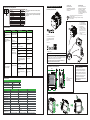
Configuring with rotary switches
0* - eSetup Easergy Pro configurable
1 - Scheme #1
2 - Scheme #2
3 - Scheme #3
4 - Scheme #4
5 - Scheme #5
6 - Scheme #6
7 - N/A
8 - N/A
9 - Test mode
0 - N/A
1 - Group 1
2 - Group 2
3 - Group 3
4 - Group 4
5 - Group 5
6 - Group 6
7 - Group 7
8 - Group 8
9 - Group 9
Note:
- * No scheme is selected. Select a scheme by eSetup
Easergy Pro.
- See the PowerLogic A3 user manual for scheme, light
group details and how to configure devices with eSetup
Easergy Pro.
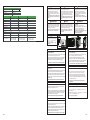
Troubleshooting
Technical data
Issues LED indication Possible causes Actions
The trip signal does
not reach the circuit
breaker.
The protection does not
trip even when a
sufficient light signal is
provided.
Sensor LED: Yellow,
steady.
Trip LED: OFF.
ON/C/E LED: Green.
Sensor LED: OFF.
Trip LED: OFF.
ON/C/E LED: Green.
Sensor LED: Yellow,
blinking.
Trip LED: OFF.
ON/C/E LED: Red.
T4 LED: Red, steady.
Communication
error.
Devices not working
due to low voltage.
ON/C/E LED: Red.
T4 LED: Red, steady.
Total distance between the
ends of the communication
bus > 100 m
A PowerLogic A3F device
supplies power to more
than one PowerLogic A3S
devices.
Remove the light and
reset the sensor.
Check the number of
connected devices or
install an auxiliary
power.
Check the sensor
and sensor wiring.
Check the sensor
wiring.
Check the distance.
The light is supplied to the
arc flash sensor for over 3 s,
the daylight blocking mode
activates.
Loosened sensor wire before
installation.
Sensor not detected.
Loosened sensor wire after
installation.
Check the sensor
wiring.
Short-circuited wiring of
sensor.
Require specific condition to
trip.
Check the
configuration.
Sensor defect. Replace the sensor.
Trip LED: Red, steady.
ON/C/E LED: Green.
Wiring error of the trip circuit. Check the wiring.
Auxiliary power supply
Uaux 48 – 240 (-20% +10%) V ac/dc
Normal operating power consumption
Passive Power over Ethernet (PoE)
6 W; (Max. 9 W)
24 V dc
T1, T3
Rated voltage 250 V ac/dc
Continuous current
5 A
Minimum making current -
Typical operation time 2 ms
Make and carry, 0.5 s 30 A
Make and carry, 3 s 15 A
Breaking capacity, AC 2 000 VA
B
reaking capacity, DC (L/R=40 ms)
at 48 V dc: 5 A
at 110 V dc: 3 A
at 220 V dc: 1 A
Terminal block
Pitch: 5.08 mm/0.2 in.
Wire dimension
Maximum 2.5 mm² (13 – 14 AWG)
Minimum 1.5 mm² (15 – 16 AWG)
250 V ac/dc
5 A 5 A
9 ms
30 A
15 A
30 A
15 A
2 000 VA
1.15 A
0.5 A 0.5 A
0.25 A
Wire dimension
Maximum 2.5 mm ² (13 – 14 AWG)
Minimum 1.5 mm ² (15 – 16 AWG)
250 V ac/dc
9 ms
2 000 VA
1.15 A
0.25 A
Wire dimension
Maximum 2.5 mm² (13 – 14 AWG)
Minimum 1.5 mm² (15 – 16 AWG)
T2 T4
100 mA @ 24 Vdc 100 mA @ 24 Vdc
p
p
p
Maximum withstand voltage 264 V ac/dc
Schneider Electric Industries SAS
35 rue Joseph Monier CS30323
92506 Rueil-Malmaison Cedex
France
www.se.com
Unpacking Arc flash protection unit
1a: A3F6P (REL52920);
or 1b: A3F12P (REL52921)
Production testing certificate
Quick start guide
Mounting accessories
(× 1: A3F6P; × 2: A3F12P)
Screws for ground connection
Washers for ground connection
Ground bar mounting screws
Ground bar
(× 1 : A3F6P; × 2: A3F12P)
1a/1b
2
3
4
5
2
03/2014
Schneider Electric Industries SAS
35 rue Joseph Monier
92500 Rueil-Malmaison
France
www.schneider-electric.com
PowerLogic A3
© 2014 Schneider Electric.
All rights reserved.
Arc flash protection unit
1 Protection relay
2 Certificate of compliance
xxxxxxx
4 Instruction sheet
5 Connector A cabling kit
6 Connector(s)
Equipment receipt
Equipment receipt
The QR code (front panel of the relay)
gives a direct access to your relay’s
website
en
This device must be installed
and serviced by qualified
electrical personnel.
Schneider Electric cannot be held
responsible for failure to follow
the instructions given on this
instruction sheet.
en
IMPORTANT NOTE
Instruction sheet
Retain for future use
Go to www.schneider-electric.com
to download the Easergy P5
reference manual and other
documents.
en
3
1a
1b
4
5
5
a
b
c
a
b
c
1a
1b
2
3
4
a
b
c
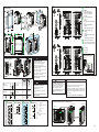
Identification and dimensions
mm
in.
1. Code
Access to product website
2. Product label
3. Instruction label
126.2
4.968
120.2
4.730
134.4
5.291
70.6
2.779
114
4.488
2
1
3
DIN rail mounting
2
1
GEX56293+06

2/12 3/12
DANGER
HAZARD OF ELECTRICAL SHOCK,
EXPLOSION OR ARC FLASH
Connect the PowerLogic A3 to ground with a
nut and washer provided using any of the
indicated ground connection positions.
Check equipotential grounding network and test
ground during installation.
Always connect the grounding conductor before
connecting the power supply.
Do not connect the auxiliary supply voltage until
the installation has been completed.
Failure to follow these instructions will result in
death or serious injury.
≥ 2.5 mm2 (AWG 12)
1.5...2.5 mm2
(AWG 16...14)
0.14...1.5 mm2
(AWG 26...16)
A3F6P: X1
A3F12P: X1, X2
A3F6P: X2, X5
A3F12P: X5
0.22...0.25 N•m
1.95...2.21 Ib-in
0.5...0.6 N•m
4.43...5.31 Ib-in
M4
3.5 mm
9/64 in.
Ø 4...6 mm
0.16...0.24 in.
2.5 mm
3/32 in.
7 mm
0.28 in.
7 mm
0.28 in.
1.5 N•m
13.28 Ib-in
S6
10
11
12
S1
S2
S3
S5
S4
X1
1
2
3
4
5
6
7
8
9
L>
L>
L>
L>
L>
L>
T4
T3
X2 A3F6P A3F12P
HSO
1
2
3
4
5
WD
WD
HSO
C
X5
T1
T2
48-240 V dc/ac
/1
2
3
4
5
6
7
8
/
S7
S8
S9
S11
S12
S10
1
2
3
4
5
6
7
8
9
10
11
12
L>
L>
L>
L>
L>
L>
X2
Terminal
T Trip relay
S Arc flash sensor
Control/trip, 5 A perm.C
LightL
WatchdogWD
High speed/high break output, trip,
5 A perm.
HSO
UNINTENTIONAL DEVICE OPERATION
This device requires advanced knowledge of the
application and setting of protection systems.
Only persons with such knowledge should be
allowed to configure and set this device.
Failure to follow these instructions can result
in death, serious injury or equipment
damage.
WARNING
DEVICE DAMAGE
Do not connect any other Ethernet network. Only PowerLogic A3 and
V321 network can be connected to the Arc EM bus.
Connected with an external power supply unit, a PowerLogic A3F unit is
capable of providing the operating power supply for only one PowerLogic
A3S unit through the communication cable. See the PowerLogic A3 user
manual for details.
Failure to follow these instructions can result in equipment damage.
NOTICE
Secured power supply and UPS are
recommended.
p
p
p
p
DANGER
HAZARD OF ELECTRICAL SHOCK,
EXPLOSION, ARC FLASH OR FIRE
Tighten the terminal screws within the
recommended range.
Protect the power supply circuit against over
currents.
Failure to follow these instructions will result in
death or serious injury.
p
p
p
p
1
2
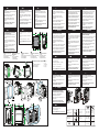
Panel mounting
mm
in.
120 ± 0.5
4.72 ± 0.02
130
5.19
90
3.54
77
± 0.5
3.03
± 0.02
5
0.2
1...5
0.04...0.2
0.7 N•m
(6.2 lb-in)
x 3
x 3
x 4
x 4
2 N•m
(17.7 lb-in)
104
4.094
144
5.669
126.2
4.968
134.4
5.291
>10
0.394
3
4
5
7
6
Connecting ground
1 N•m
(8.85 lb-in)
A3F12P A3F6P
x 2
ON/C/E
RESET/
INSTALL
T1
T4
S1
S2
S3
S4
S5
S6
T3
T2
121110987654321
X1
COM
12111098765432
21
1
S1 S2 S3 S4 S5 S6
Light GroupScheme X2 T4 T3
X5
1
1
2
2
3
3
4
4
5
5
6 7 8
U T1 T2
S
123 4 5 6 78
ON/C/E
RESET/
INSTALL
T1
S10
S11
S12
S8
S9
S1
S2
S3
S4
S5
S6
S7
T2
121110987654321
X1
COM
12111098765432
21
1
S1 S2 S3 S4 S5 S6
121110987654321
Light GroupScheme X2
X5
1 2 3 4 5 6 7 8
U T1 T2
S
123 4 5 6 78
S12
1211 10 9 8 7 6 5 4 3 2 1
S11 S10 S9 S8 S7
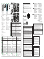
Reset/install button
A3F12P
A3F6P 1
Rotary configuration switches4
5Com 1/2: Connecting the PowerLogic
A3 device, VAMP 321(V321) unit, or a
PC.
X1 connector6
X2 connector7
X5 connector8
2ON/C/E:
Green, steady: In service.
Green, blink: Communicating.
Orange, steady: Test mode.
Red: Error.
3Sensor and trip output status
(A3F6P):
T1...T3:
Red, steady: Output relay activation.
T4:
Red, steady: Self-diagnostics.
S1...S6:
Yellow, steady: Sensor activation.
3Sensor and trip output status
(A3F12P):
T1...T2:
Red, steady: Output relay activation.
S1...S12:
Yellow, steady: Sensor activation.
12
3
4
7 8 6
5
12
3
4
7 8 6
5
PowerLogic A3F
PowerLogic A3S
V321
Connecting with the V321 or PowerLogic A3
Connecting with a PC
PowerLogic A3
COM
1
12
11
10
9
8
7
6
5
4
3
2
1
X1
12
11
10
9
8
7
6
5
4
3
2
2
1
S1
S2
S3
S4
S5
S6
5

PowerLogicTM A3F6P/A3F12P
5/12
06/2023
Schneider Electric Industries SAS
35 rue Joseph Monier CS30323
92506 Rueil-Malmaison Cedex
France
www.se.com
pl
Equipement de protection arc flash
Lichtbogenschutzeinrichtung
Unità di protezione contro l'arco elettrico
it
de
fr
Unidad de protección de arco eléctrico
es
Unidade de proteção contra arco elétrico
br/pt
Устройство защиты от дуговых замыканий
ru
zh
La instalación, el
mantenimiento, la operación, el
servicio y el mantenimiento de
este equipo deben ser llevados
a cabo solamente por el
personal cualificado. Schneider
Electric no asume ninguna
responsabilidad por las
consecuencias derivadas del
uso de este material.
OBSERVACIÓN IMPORTANTE
Le apparecchiature elettriche
devono essere installate,
utilizzate, riparate e sottoposte
a manutenzione solo da
personale qualificato.
Schneider Electric non si
assume alcuna responsabilità
per eventuali conseguenze
derivanti dall'uso di questo
materiale.
IMPORTANTE
Elektrische Geräte dürfen nur
von qualifiziertem Personal
installiert, bedient, gewartet
und instand gehalten werden.
Schneider Electric übernimmt
keine Haftung für Folgen, die
sich aus der Verwendung
dieses Dokuments ergeben.
WICHTIGER HINWEIS
Les équipements électriques
doivent être installés, utilisés,
maintenus uniquement par un
personnel qualifié. Schneider
Electric décline toute
responsabilité pour les
conséquances découlant de
l'utilisation de ce document.
NOTE IMPORTANTE
Equipamentos elétricos devem
ser instalados, operados,
reparados e mantidos apenas
por pessoal qualificado.
Nenhuma responsabilidade é
assumida pela Schneider
Electric por quaisquer
consequências decorrentes do
uso deste material.
NOTA IMPORTANTE
此电气设备必须由具有专业资格的
人员进行安装、操作、维修和维护
。对于因使用本说明而导致的任何
后果,施耐德电气概不负责。
重要注意事项
Установка, эксплуатация,
обслуживание и ремонт
электрооборудования должны
осуществляться только
квалифицированным
персоналом. Компания
Schneider Electric не несет
ответственности за любые
последствия, возникшие в
результате использования
данного материала.
ВАЖНО!
it
de
fr
es
br/pt ru
zh
弧光保护装置
8/12
注意
产品篡改
我们的产品在出厂时进行过密封包装。如果在接收产品时发现包装开封或密封材料
破损,将无法保证产品内含信息的保密性和真实性。
不遵守此指示可能导致产品内含信息的保密性和真实性受到影响。
NOTE
CORRUPTION DE PRODUIT
Nos produits quittent notre usine dans des emballages d'origines fermés et
scellés. A la livraison, si l'emballage est ouvert ou si le scellé est brisé, la
confidentialité et l'authenticité des informations contenues dans les produits ne
sont plus garanties.
Le non-respect de cette instruction peut compromettre la confidentialité et
authenticité des informations contenues dans les produits.
ATENCIÓN
MANIPULACIÓN DEL PRODUCTO
Nuestros productos salen de fábrica en empaques originales cerrados y sellados.
En el momento de la entrega, si el embalaje está abierto o el sello roto, no se
puede asegurar la confidencialidad y autenticidad de la información contenida en
los productos.
No atender estas instrucciones puede comprometer la confidencialidad y
autenticidad de la información contenida en los productos.
AVISO
VIOLAÇÃO DO PRODUTO
Nossos produtos saem de nossa fábrica em embalagens originais fechadas e
lacradas. Na entrega, se a embalagem estiver aberta ou o lacre estiver rompido,
a confidencialidade e autenticidade das informações contidas nos produtos não
podem ser asseguradas.
O não cumprimento desta instrução pode resultar em comprometimento da
confidencialidade e autenticidade das informações contidas nos produtos.
ВНИМАНИЕ
ПОДЛИННОСТЬ ПРОДУКЦИИ
Вся наша продукция поставляется в закрытой опечатанной оригинальной
упаковке. Если упаковка вскрыта или повреждена пломба, то
конфиденциальность и достоверность содержащейся информации о
продукции не могут быть обеспечены.
Невыполнение данных требований может повлечь нарушения
конфиденциальности и подлинности информации о продукции.
NOTA
MANOMISSIONE DEL PRODOTTO
I nostri prodotti lasciano la nostra fabbrica nella confezione originale chiusa e
sigillata. Al momento della consegna, se l'imballo è aperto o il sigillo è rotto, non
può essere garantita la riservatezza e l'autenticità delle informazioni contenute
nei prodotti.
L’omissione di tale procedura può compromettere la riservatezza e l’autenticità delle
informazione contenute nel prodotto stesso.
HINWEIS
PRODUKTMANIPULATION
Unsere Produkte verlassen unser Werk in geschlossenen, versiegelten
Originalverpackungen. Wenn beim Erhalt der Lieferung die Transportverpackung
oder das Verpackungssiegel geöffnet sind, so sind Vertraulichkeit und
Unverfälschtheit der in den Produkten enthaltenen Informationen nicht mehr
sichergestellt.
Die Nichtbeachtung dieser Anweisungen kann zu einer Beeinträchtigung der
Vertraulichkeit und Unverfälschtheit der in den Geräten enthaltenen Informationen
führen.
Reset/bouton d'installation
Commutateur rotatif de configuration
Com 1/2: Connexion du PowerLogic
A3, VAMP 321(V321) or à un PC.
Connecteur X1, X2, X5
ON/C/E:
Vert, allumé : En service.
Vert, clignotant : En communication.
Orange, allumé: Mode test.
Rouge : Erreur.
Etat capteur et sortie relais (A3F6P):
T1...T3:
Rouge, allumé: Sortie Relais activée.
T4:
Rouge, allumé: Autodiagnostic.
S1...S6:
Jaune, allumé : Capteur activé.
Etat capteur et sortie relais (A3F12P):
T1...T2:
Rouge, allumé: Sortie Relais activée.
S1...S12:
Jaune, allumé : Capteur activé.
Pulsante Ripristina/Installa
Selettore di configurazione
Connettore X1, X2, X5
ON/C/E:
Verde, fisso: In servizio.
Verde, lampeggiante: Comunicazione in corso.
Arancione, fisso: Modalità test.
Rosso: Errore.
Stato del sensore e dell'uscita di scatto
(A3F6P):
T1...T3:
Rosso, fisso: Attivazione del relè di uscita.
T4:
Rosso, fisso: Autodiagnostica.
S1...S6:
Giallo, fisso: Attivazione del sensore.
1
1
4
4
5
5
6,7,8
6,7,8
2
2
3
3
3
3
Botón de reinicio/instalación
Conmutadores de configuración giratorios
Conector X1, X2, X5
ON/C/E:
Verde fijo: En servicio.
Verde, parpadeo: Comunicando.
Naranja fijo: Modo de prueba.
Rojo: Error.
Estado de sensor y salida de disparo
(A3F6P):
T1...T3:
Rojo fijo: Activación del relé de salida.
T4:
Rojo fijo: Autodiagnóstico.
S1...S6:
Amarillo fijo: Activación del sensor.
Botão de Reset/Instalação
Chave rotativa de configuração
Conector X1, X2, X5
ON/C/E:
Verde, contínuo: Em serviço.
Verde, piscando: Comunicando.
Laranja, contínuo: Modo de teste.
Vermelho: Erro.
Status do sensor e da saída de trip
(A3F6P):
T1...T3:
Vermelho, contínuo: Ativação da saída do relé.
T4:
Vermelho, contínuo: Autodiagnóstico.
S1...S6:
Amarelo, contínuo: Ativação do sensor.
Кнопка сброса/установки
Поворотные переключатели настроек
Com 1/2: Collegamento del
dispositivo PowerLogic A3, dell'unità
VAMP 321(V321) o di un PC.
Com 1/2: Conexión del dispositivo
PowerLogic A3, la unidad VAMP
321(V321) o un PC.
Com 1/2: Conectando o o dispositivo
PowerLogic A3, unindade VAMP
321(V321) ou a um PC.
Com 1/2: Подключение PowerLogic
A3, VAMP 321(V321) или ПК.
Разъем X1, X2, X5
ON/C/E:
Зеленый/горит : Работа.
Зеленый/мигание : Связь.
Оранжевый/горит : Тестовый режим.
Красный : Ошибка.
Состояние датчиков и вых. реле
(A3F6P):
T1...T3:
Красный/горит : Работа вых. реле.
T4:
Красный/горит : Самодиагностика.
S1...S6:
Желтый/горит : Работа датчика.
Stato del sensore e dell'uscita di scatto
(A3F12P):
T1...T2:
Rosso, fisso: Attivazione del relè di uscita.
S1...S12:
Giallo, fisso: Attivazione del sensore.
Estado de sensor y salida de disparo
(A3F12P):
T1...T2:
Rojo fijo: Activación del relé de salida.
S1...S12:
Amarillo fijo: Activación del sensor.
Status do sensor e da saída de trip
(A3F12P):
T1...T2:
Vermelho, contínuo: Ativação da saída
do relé.
S1...S12:
Amarelo, contínuo: Ativação do sensor.
Состояние датчиков и вых. реле
(A3F12P):
T1...T2:
Красный/горит : Работа вых. реле.
S1...S12:
Желтый/горит : Работа датчика.
‚Reset / Install‘-Taster
Drehschalter für Konfiguration
COM 1/2: Anschluss eines PowerLogic A3,
eines VAMP 321(V321) oder eines PC.
Klemmenblock X1, X2, X5
ON/C/E:
Grün (leuchtend): In Betrieb.
Grün (blinkend): Kommunikation.
Geld (leuchtend): Testmodus.
Rot: Fehler.
LEDs für Sensoren und Auslöserelais (A3F6P):
T1...T3:
Rot (leuchtend): Auslöserelais aktiviert.
T4:
Rot (leuchtend): Selbstdiagnose.
S1...S6:
Gelb (leuchtend): Sensor aktiviert.
LEDs für Sensoren und Auslöserelais (A3F12P):
T1...T2:
Rot (leuchtend): Auslöserelais aktiviert.
S1...S12:
Gelb (leuchtend): Sensor aktiviert.
Borna
T Relé de Disparo
S Sensor de Arco Eléctrico
Control/Disparo, 5 A perm.C
LuzL
WatchdogWD
HSO
Se recomienda el uso de fuente de
alimentación segura y UPS.
Salida de Alta velocidad/alta capacidad
de ruptura, disparo, 5 A perm.
Terminal
T Relé de trip
S Sensor de arco
Controle/trip, 5 A perm.C
LuzL
WatchdogWD
HSO
Fonte de alimentação segura e UPS
são recomendados.
Saída de alta velocidade/alta
interrupção, trip, 5 A perm.
终端
T跳闸继电器
S弧光传感器
控制/跳闸,持续电流5 AC
光L
看门狗WD
高速/重载输出,跳闸,持续电流5 AHSO
建议使用安全的电源和 UPS。
Borne
T Sortie relais
S Capteur d'Arc flash
Contrôle/déclenchement, 5 A perm.
C
LumièreL
Chien de gardeWD
Sortie rapide/déclenchement rapide,
5 A perm.
HSO
UPS ou alimentation secourue
recommandée.
Klemme
T Auslöserelais
S Lichtbogensensor
Steuer-/Auslöserelais, 5 A DauerstromC
LichtL
WatchdogWD
HSO
Eine gesicherte Spannungsversorgung
und eine USV werden empfohlen.
Auslöserelais mit Leistungskontakten,
5 A Dauerstrom.
Клеммник
TРеле отключения
SДатчик дуги
реле управления/отключения, 5 A.C
СветL
Самодиагностика (WD)WD
Быстродействующее/усиленное реле,
5 A.
HSO
Рекомендуется использовать
надежные источники питания и ИБП.
Morsetti
T Relè di scatto
S Sensore d'arco
Controllo/scatto, 5 A perm.C
LuceL
"Watchdog"WD
HSO
Si raccomanda una alimentazione
ausiliaria sicura e un UPS di
alimentazione.
Uscita alta velocità/alta interruzione,
scatto, 5 A perm.
S6
10
11
12
S1
S2
S3
S5
S4
X1
1
2
3
4
5
6
7
8
9
L>
L>
L>
L>
L>
L>
T4
T3
X2 A3F6P A3F12P
HSO
1
2
3
4
5
WD
WD
HSO
C
X5
T1
T2
48-240 V dc/ac
/1
2
3
4
5
6
7
8
/
S7
S8
S9
S11
S12
S10
1
2
3
4
5
6
7
8
9
10
11
12
L>
L>
L>
L>
L>
L>
X2
it
de
fr
es br/pt ru
© 2023 Schneider Electric.
All rights reserved.
重置/安装按钮1
2ON/C/E:
绿色,常亮:运行中。
绿色,闪烁:通讯中。
橙色,常亮:测试模式。
红色:错误。
3传感器和跳闸输出状态 (A3F6P):
T1...T3:
红色,常亮:输出继电器激活。
T4:
红色,常亮:自诊断。
S1...S6:
黄色,常亮:传感器激活。
3传感器和跳闸输出状态 (A3F12P):
T1...T2:
红色,常亮:输出继电器激活。
S1...S12:
黄色,常亮:传感器激活。
旋转配置开关4
5Com 1/2:连接 PowerLogic A3、
VAMP 321(V321)或电脑。
X1, X2, X5连接器
6,7,8
zh
de
fr
it es
br/pt ru
zh
A3F6P
A3F12P
ON/C/E
RESET/
INSTALL
T1
T4
S1
S2
S3
S4
S5
S6
T3
T2
121110987654321
X1
COM
12111098765432
21
1
S1 S2 S3 S4 S5 S6
Light GroupScheme X2 T4 T3
X5
1
1
2
2
3
3
4
4
5
5
6 7 8
U T1 T2
S
123 4 5 6 78
12
3
4
7 8 6
5
ON/C/E
RESET/
INSTALL
T1
S10
S11
S12
S8
S9
S1
S2
S3
S4
S5
S6
S7
T2
121110987654321
X1
COM
12111098765432
21
1
S1 S2 S3 S4 S5 S6
121110987654321
Light GroupScheme X2
X5
1 2 3 4 5 6 7 8
U T1 T2
S
123 4 5 6 78
S12
1211 10 9 8 7 6 5 4 3 2 1
S11 S10 S9 S8 S7
12
3
4
7 8 6
5
RISQUE D’ELECTROCUTION, D’EXPLOSION
OU D’ARC ELECTRIQUE
Coupez l’alimentation générale de cet appareil
avant toute intervention sur l’appareil.
Utilisez toujours un dispositif de détection de
tension approprié pour confirmer l’absence de
tension.
Installez tous les équipements, les protection et
le volet avant de mettre sous tension..
Si ces directives ne sont pas respectées, cela
entraînera la mort ou des blessures graves.
DANGER
p
p
p
GEFÄHRDUNG DURCH ELEKTRISCHEN
SCHLAG, EXPLOSION ODER LICHTBÖGEN
Vor Arbeiten an diesem Gerät ist das Gerät
spannungsfrei zu schalten!
Zum Feststellen der Spannungsfreiheit ist ein
geeignetes Spannungsmessgerät zu
verwenden.
Vor dem Einschalten der Spannungsver-
sorgung sind alle Vorrichtungen, Klappen und
Abdeckungen am Gerät wieder anzubringen.
Die Nichtbefolgung dieser Anweisungen führt zu
schweren Verletzungen oder Tod.
GEFAHR
p
p
p
GEX56293+06

触电、爆炸或电弧光的危险
对设备或设备内部开展工作前,请关闭该设备
所有电源。
始终使用适合的电压检测设备以确认所有电源
已关闭。
在设备通电前安装所有装置、门和盖板。
不遵守这些说明操作将导致死亡或严重的人身伤
害。
危险
p
p
p
1. Code
Accès au site internet du produit
2. Etiquette produit
3. Etiquette d'instructions
Identification et dimensions
1. Code
Link zur Produktwebsite
2. Produktetikett
3. Anweisungsetikett
Gerätekennzeichnung und
Abmessungen 1. Codice
Accesso al sito internet del prodotto
2. Etichetta prodotto
3. Etichetta istruzioni
Identificazione e dimensioni
1. Código
Acceso al sitio web del producto
2. Rótulo del Producto
3. Rótulo de Instrucciones
Identificación y dimensiones
1. Código
Acesso ao site do produto
2. Etiqueta do produto
3. Etiqueta de instruções
Identificação e dimensões
1. Код
Доступ к данным на вебсайте
2. Этикетка устройства
3. Этикетка инструкции
Идентификация и габаритные размеры
1. 二维码
产品网站链接
2. 产品标签
3. 说明标签
标识和尺寸
DANGER
RISQUE D’ELECTROCUTION, D’EXPLOSION
OU D’ARC ELECTRIQUE
Connecter le PowerLogic A3 à la terre en
utilisant la vis et l'écrou founi en respectant les
indications.
Vérifiez le réseau de mise à la terre
équipotentielle et testez la terre pendant
l'installation.
Toujours connecter le conducteur de terre
avant de connecter l'alimentation.
Ne pas connecter l'alimentation auxiliaire avant
que l'installation ne soit terminée.
Si ces directives ne sont pas respectées, cela
entraînera la mort ou des blessures graves.
p
p
p
p
GEFAHR
GEFÄHRDUNG DURCH ELEKTRISCHEN SCHLAG,
EXPLOSION ODER LICHTBÖGEN
Schließen Sie das PowerLogic A3 mit der mitgelieferten
Mutter und Unterlegscheibe über einen der
angegebenen Erdungsanschlüsse an Erde an.
Testen Sie das Potentialausgleichssystem und prüfen
Sie während der Installation die korrekte Erdung.
Schließen Sie vor dem Anschluss der Spannungsver-
sorgung stets zuerst den Schutzleiter an.
Schließen Sie vor dem Anschluss der Spannungsver-
sorgung stets zuerst den Schutzleiter an.
Die Nichtbefolgung dieser Anweisungen führt zu
schweren Verletzungen oder Tod.
p
p
p
p
PERICOLO
RISCHIO DI FOLGORAZIONE, ESPLOSIONE
O ARCO
Collegare il PowerLogic A3 a terra con un dado
e una rondella forniti utilizzando una delle
posizioni di collegamento di terra indicate.
Controllare la rete equipotenziale di messa a
terra e testare la terra durante l'installazione.
Collegare sempre il conduttore di terra prima di
collegare l'alimentazione.
Non collegare la tensione di alimentazione
ausiliaria fino a che l'installazione è stata
completata.
Il mancato rispetto di queste istruzioni può
provocare la morte o gravi lesioni.
p
p
p
p
PELIGRO
RIESGO DE DESCARGA ELÉCTRICA,
EXPLOSIÓN O ARCO ELÉCTRICO
Conectar el PowerLogic A3 a tierra con la tuerca
y arandela provistas utilizando cualquiera de las
posiciones de conexión a tierra indicadas.
Compruebar la red de puesta a tierra
equipotencial y la puesta a tierra durante la
instalación.
Conectar siempre el conductor de puesta a tierra
antes de conectar la fuente de alimentación.
No conectar la tensión auxiliar de alimentación
hasta que la instalación se ha completado.
El incumplimiento de estas instrucciones podrá
causar la muerte o lesiones serias.
p
p
p
p
危险
触电、爆炸或电弧光的危险
用提供的螺母和垫圈将 PowerLogic A3 接地到任
何指定的接地连接位置。
安装时检查等电位接地网络,并测试接地。
在连接电源之前,请务必可靠接地。
安装完成前,不要连接辅助电源电压。
不遵守这些说明操作将导致死亡或严重的人身伤害。
p
p
p
p
PERIGO
RISCO DE CHOQUE ELÉCTRICO, EXPLOSÃO
OU ARCO
Conecte o PowerLogic A3 ao aterramento usando
porca e arruela fornecidas, usando qualquer uma
das posições de conexão de aterramento
indicadas.
Verifique a equipontencialização da malha de
aterramento e teste o aterramento durante a
instalação.
Sempre conecte o condutor de aterramento antes
de conectar a fonte de alimentação.
Não conecte a tensão de alimentação auxiliar até
que a instalação foi concluída.
A não observância destas instruções causará a
morte ou ferimentos graves.
p
p
p
p
ОПАСНО!
ОПАСНОСТЬ ПОРАЖЕНИЯ
ЭЛЕКТРИЧЕСКИМ ТОКОМ, ВЗРЫВА ИЛИ
ВОЗНИКНОВЕНИЯ ДУГИ
Подключите устройство PowerLogic A3 к земле
с помощью прилагаемой гайки и шайбы.
Проверьте эквипотенциальность заземляющей
сети и заземление во время монтажа.
Всегда подключайте заземляющий проводник
перед подключением питания.
Не подключайте питание устройства если
монтаж еще не выполнен .
Несоблюдение этих инструкций может привести
к смерти или серьезным травмам.
p
p
p
p
DANGER
RISQUE D'ELECTROCUTION, D'EXPLOSION
OU D'ECLAIR D'ARC FLASH OU D'INCENDIE
Serrez les vis des borniers dans la plage
recommandée.
Protéger le circuit de l’alimentation contre les
surintensités.
Si ces directives ne sont pas respectées, cela
entraînera la mort ou des blessures graves.
p
p
GEFAHR
GEFÄHRDUNG DURCH ELEKTRISCHEN SCHLAG,
EXPLOSION, LICHTBÖGEN ODER BRÄNDE
Ziehen Sie die Schrauben mit dem empfohlenen
Anziehdrehmoment an.
Schützen Sie den Stromkreis der Spannungsver-
sorgung gegen Überstrom.
Die Nichtbefolgung dieser Anweisungen führt zu
schweren Verletzungen oder Tod.
p
p
PERICOLO
RISCHIO DI FOLGORAZIONE, ESPLOSIONI,
ARCHI ELETTRICI E INCENDI
Serrare le viti dei morsetti entro l'intervallo
consigliato.
Proteggere il circuito d'alimentazione contro le
sovracorrenti.
Il mancato rispetto di queste istruzioni può
provocare la morte o gravi lesioni.
p
p
ОПАСНО!
ОПАСНОСТЬ ПОРАЖЕНИЯ
ЭЛЕКТРИЧЕСКИМ ТОКОМ, ВЗРЫВА,
ВОЗНИКНОВЕНИЯ ДУГИ ИЛИ ПОЖАРА
Затяните винты клемм в пределах
рекомендуемого диапазона.
Используйте защиту от перегрузки по току в
цепи питания.
Несоблюдение этих инструкций может
привести к смерти или серьезным травмам.
p
p
危险
触电、爆炸、电弧光或火灾的危险
在推荐扭矩范围内拧紧端子螺钉。
保护电源回路避免过流。
不遵守这些说明操作将导致死亡或严重的人身伤害。
p
p
PERIGO
RISCO DE CHOQUE ELÉTRICO, EXPLOSÃO,
ARCO ELÉTRICO OU INCÊNDIO
Aperte os parafusos dos terminais dentro da
faixa recomendada.
Proteja a fonte de alimentação contra
sobrecorrentes.
A não observância destas instruções causará a
morte ou ferimentos graves.
p
p
PELIGRO
PELIGRO DE DESCARGA ELÉCTRICA,
EXPLOSIÓN O ARCO ELÉCTRICO E INCENDIO
Apretar los tornillos del terminal dentro del rango
recomendado.
Proteger el circuito de alimentación contra las
sobreintensidades.
El incumplimiento de estas instrucciones podrá
causar la muerte o lesiones serias.
p
p
≥ 2.5 mm2 (AWG 12)
1.5...2.5 mm2
(AWG 16...14)
0.14 ...1.5 mm2
(AWG 26...16)
0.22...0.25 N•m
1.95...2.21 Ib-in
0.5...0.6 N•m
4.43...5.31 Ib-in
M4
3.5 mm
9/64 in.
Ø 4...6 mm
0.16...0.24 in.
2.5 mm
3/32 in.
7 mm
0.28 in.
7 mm
0.28 in.
1.5 N•m
13.28 Ib-in
A3F6P: X1
A3F12P: X1, X2
A3F6P: X2, X5
A3F12P: X5
7/12
6/12
de
fr it es br/pt
ru zh
mm
in.
126.2
4.968
134.4
5.291
70.6
2.779
114
4.488
2
1
3
120.2
4.730
2
1
1
2
mm
in.
120 ± 0.5
4.72 ± 0.02
130
5.19
90
3.54
77
± 0.5
3.03
± 0.02
5
0.2
1...5
0.04...0.2
0.7 N•m
(6.2 lb-in)
x 3
x 3
x 4
x 4
2 N•m
(17.7 lb-in)
104
4.094
144
5.669
126.2
4.968
134.4
5.291
>10
0.394
3
4
5
7
6
1 N•m
(8.85 lb-in)
A3F12P A3F6P
x 2
RIESGO DE DESCARGA ELÉCTRICA,
EXPLOSIÓN O ARCO ELÉCTRICO
Desconectar la alimentación general del equipo
antes de manipularlo.
Utilice siempre un dispositivo de detección de
tensión apropiado para confirmar la ausencia
de tensión.
Instalar todos los dispositivos, tapas y cubiertas
antes de volver a conectar el equipo.
El incumplimiento de estas instrucciones podrá
causar la muerte o lesiones serias.
PELIGRO
p
p
p
RISCO DE CHOQUE ELÉCTRICO,
EXPLOSÃO OU ARCO
Desligue toda a alimentação elétrica deste
equipamento antes de trabalhar no interior do
equipamento.
Utilize sempre um dispositivo de detecção de
tensão apropriado para confirmar a ausência
de tensão.
Instale todos os dispositivos, portas e tampas
antes de ligar este equipamento.
A não observância destas instruções causará a
morte ou ferimentos graves.
PERIGO
p
p
p
RISCHIO DI FOLGORAZIONE, ESPLOSIONE
O ARCO
Prima di effettuare lavori sul dispositivo togliere
l’alimentazione elettrica.
Usare sempre uno strumento adeguato per
verificare l’assenza di tensione.
Prima di riaccendere l'apparecchiatura,
installare tutti i dispositivi, gli sportelli e i
coperchi.
Il mancato rispetto di queste istruzioni può
provocare la morte o gravi lesioni.
PERICOLO
p
p
p
ОПАСНОСТЬ ПОРАЖЕНИЯ
ЭЛЕКТРИЧЕСКИМ ТОКОМ, ВЗРЫВА ИЛИ
ВОЗНИКНОВЕНИЯ ДУГИ
Перед производством работ с данным
устройством отключите все его источники
питания.
Обязательно используйте индикатор
напряжения для подтверждения отсутствия
напряжения.
Установите все устройства, двери и крышки
перед включением питания данного
оборудования.
Несоблюдение этих инструкций может
привести к смерти или серьезным травмам.
ОПАСНО!
p
p
p

DÉCLENCHEMENT INTEMPESTIF
Cet appareil nécessite une connaissance approfondie
des applications et réglages des systèmes de
protection électrique. Seul le personnel ayant les
compétences requises peut configurer et calibrer cet
équipement.
Le non-respect de ces instructions peut entraîner
la mort, des blessures graves ou des dommages
matériels.
ATTENTION
INTERVENTO INVOLONTARIO DEL DISPOSITIVO
Questo dispositivo richiede una conoscenza avanzata
dell'applicazione e configurazione di sistemi di
protezione. La configurazione di questo dispositivo
dovrebbe essere eseguita solamente da personale
altamente qualificato.
Il mancato rispetto di queste istruzioni può
provocare la morte, lesioni gravi o danni materiali.
ATTENZIONE
UNBEABSICHTIGTE BETÄTIGUNG DES GERÄTS
Für die Bedienung dieses Geräts sind
Fachkenntnisse über die Anwendung und Einstellung
von Schutzsystemen erforderlich. Nur Personen, die
über solche Kenntnisse verfügen, dürfen mit der
Konfiguration und Einstellung dieses Geräts betraut
werden.
Die Nichtbefolgung dieser Anweisungen kann zu
Tod, schweren Verletzungen oder Sachschäden
führen.
WARNUNG
OPERACIÓN ININTENCIONADA DEL EQUIPO
Este dispositivo requiere un conocimiento avanzado
de la aplicación y ajuste de sistemas de protección.
Sólo personas con tal conocimiento tienen permiso
para configurar y ajustar este relé.
No atender estas instrucciones puede provocar la
muerte, lesiones graves o daños materiales.
ADVERTENCIA
OPERAÇÃO NÃO INTENCIONAL DO DISPOSITIVO
Este dispositivo requer conhecimento avançado de
aplicação e configuração de sistemas de proteção.
Apenas pessoas com devido conhecimento devem ser
permitidas a configurar este dispositivo.
O descumprimento dessas instruções podem
causar morte, ferimentos graves e danos ao
equipamento.
ALERTA
设备意外动作
该设备需要对保护系统的应用和设置有
深入的了解。只有具备相应知识的人员
才可以对设备进行配置。
不遵守这些指令可能导致死亡,严重伤
害或设备损坏。
警告
НЕПРЕДНАМЕРЕННОЕ СРАБАТЫВАНИЕ
УСТРОЙСТВА
Устройство требует соответствующей
квалификации пользователя в области релейной
защиты. К работе с устройством должен
допускаться только обученный персонал.
Несоблюдение этих инструкций может привести
к смерти, серьезным травмам или
повреждению оборудования.
ВНИМАНИЕ!
DANO NO DISPOSITIVO
Não conecte nenhuma outra rede Ethernet. Somente a rede PowerLogic
A3 e V321 pode ser conectada ao barramento Arc EM.
Conectado a uma unidade de alimentação externa, uma unidade
PowerLogic A3F é capaz de fornecer a alimentação operacional para
apenas uma unidade PowerLogic A3S através do cabo de comunicação.
Consulte o manual do usuário PowerLogic A3 para obter detalhes.
O descumprimento dessas instruções podem causar danos ao equipamento.
AVISO
设备损坏
请勿连接任何其他以太网网络。只有 PowerLogic A3 和 V321 网络可以连
接到 Arc EM 总线。
PowerLogic A3F 与外部电源连接后,通过通讯电缆仅能为一台 PowerLogic
A3S供电。详情见PowerLogic A3用户手册。
不遵守这些指令可能会导致设备损坏。
注意
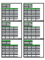
技术数据
辅助电源
辅助电源电压 48 – 240 (-20% +10%) V ac/dc
正常功率消耗
电源来源于网络连接PoE
6 W; (最大9 W)
24 V dc
T1, T3
额定电压 250 V ac/dc
持续承载电流
5 A
最小关合电流 -
典型跳闸时间 2 ms
短时持续电流,0.5 s 30 A
短时持续电流,3 s 15 A
交流开断容量 2 000 VA
直流开断容量 (L/R=40 ms)
48 V dc: 5 A 1.15?
110 V dc: 3 A 0.5?
220 V dc: 1 A 0.25?
接线端子
针距:5.08 mm/0.2 in.
线径
最大 2.5 mm² (13 – 14 AWG)
最小 1.5 mm² (15 – 16 AWG)
线径
最大 2.5 mm² (13 – 14 AWG)
最小 1.5 mm² (15 – 16 AWG)
线径
最大 2.5 mm² (13 – 14 AWG)
最小 1.5 mm² (15 – 16 AWG)
250 V ac/dc
5 A 5 A
9 ms
30 A
15 A
30 A
15 A
2 000 VA
1.15 A
0.5 A 0.5 A
0.25 A
250 V ac/dc
9 ms
2 000 VA
1.15 A
0.25 A
T2 T4
100 mA @ 24 Vdc 100 mA @ 24 Vdc
最大耐受电压 264 V ac/dc
9/12
12/12
APPAREIL DÉFAILLANT
Ne connectez aucun autre réseau Ethernet. Seuls les réseaux PowerLogic
A3 et V321 peuvent être connectés au bus Arc EM.
Connectée à une alimentation exterieure, PowerLogic A3F est capable de
fournir l'alimentation à une seule unité PowerLogic A3S via le câble de
communication. Se référer au manuel d'utilisateur PowerLogic A3
Le non-respect de ces instructions peut entraîner des dommages matériels.
NOTE
p
p
EQUIPO DAÑADO
No conectar a ninguna otra red Ethernet. Solo la red PowerLogic A3 y V321
se puede conectar al bus Arc EM.
Conectada a una fuente de alimentación externa, una PowerLogic A3F es
capaz de proporcionar la alimentación de operación para una unica
PoweLogic A3S a través del cable de comunicación. Mirar el manual de
usuario del PowerLogic A3 para más detalles.
El uso indebido de estas instrucciones puede provocar daños en el equipo.
ATENCIÓN
p
p
Geräteschäden
Schließen Sie das Gerät nicht an das Ethernet an. Es dürfen nur PowerLogic
A3 und V321 an den Lichtbogen-E/A-Bus angeschlossen werden.
Bei Anschluss an eine externe Spannungsquelle kann ein PowerLogic A3F
nur ein einziges PowerLogic A3S über das Kommunikationskabel mit
Spannung versorgen. Für weitere Informationen siehe die PowerLogic A3
Betriebsanleitung.
Die Nichtbefolgung dieser Anweisungen kann zu Geräteschäden führen.
HINWEIS
p
p
DANNI AL DISPOSITIVO
Non collegare nessun'altra rete Ethernet. Solo la rete PowerLogic A3 e
V321 può essere collegata al bus Arc EM.
Collegata con un'unità di alimentazione esterna, un'unità PowerLogic A3F
è in grado di fornire l'alimentazione per il funzionamento di una sola unità
PowerLogic A3S tramite il cavo di comunicazione. Per ulteriori dettagli
riferirsi al manuale utente di PowerLogic A3.
Il mancato rispetto di queste istruzioni può provocare danni materiali.
NOTA
p
p
p
p
ПОВРЕЖДЕНИЕ УСТРОЙСТВА
Нельзя подключать любую сеть Ethernet. Только сети устройств
PowerLogic A3 и V321 могут быть подключены к шине Arc EM.
Устройство PowerLogic A3F, подключенное к внешнему источнику
питания, способно обеспечивать питание по кабелю связи только
одного устройства PowerLogic A3S. Подробности см. в руководстве
пользователя PowerLogic A3.
Несоблюдение этих инструкций может привести к повреждению
оборудования.
ВНИМАНИЕ
p
p
p
p
PowerLogic A3
V321
PowerLogic A3F
PowerLogic A3S
COM
1
12
11
10
9
8
7
6
5
4
3
2
1
X1
12
11
10
9
8
7
6
5
4
3
2
2
1
S1
S2
S3
S4
S5
S6
5

Caractéristiques techniques
Alimentation auxiliaire
Uaux 48 – 240 (-20% +10%) V ca/cc
Consommation en fonctionnement nominal
Alimentation par câble Ethernet (POE)
6 W; (Max. 9 W)
24 Vcc
T1, T3
Tension nominale 250 V ca/cc
Courant Permanent
5 A
Courant minimum -
Temps de fonctionnement moyen 2 ms
Capacité de coupure, 0,5 s 30 A
Capacité de coupure, 3 s 15 A
Pouvoir de coupure, AC 2 000 VA
Pouvoir de coupure, DC (L/R=40 ms)
à 48 Vcc: 5 A
à 110 Vcc: 3 A
à 220 Vcc: 1 A
Bornier
Pas: 5.08 mm/0.2 in.
Dimension fil
Maximum 2.5 mm² (13 – 14 AWG)
Minimum 1.5 mm² (15 – 16 AWG)
Dimension fil
Maximum 2.5 mm² (13 – 14 AWG)
Minimum 1.5 mm² (15 – 16 AWG)
Dimension fil
Maximum 2.5 mm² (13 – 14 AWG)
Minimum 1.5 mm² (15 – 16 AWG)
250 V ca/cc
5 A 5 A
9 ms
30 A
15 A
30 A
15 A
2 000 VA
1.15 A
0.5 A 0.5 A
0.25 A
250 V ca/cc
9 ms
2 000 VA
1.15 A
0.25 A
T2 T4
100 mA @ 24 Vcc 100 mA @ 24 Vcc
Tension maximale 264 V ca/cc
Technische Daten
Hilfsspannungsversorgung
UH48 – 240 (-20% +10%) V AC/DC
Leistungsaufnahme bei Normalbetrieb
Passive Power over Ethernet (PoE)
6 W; (max. 9 W)
24 V DC
T1, T3
Nennspannung 250 V AC/DC
Dauerstrom
5 A
Min. Einschaltstrom -
Typische Ansprechzeit 2 ms
Einschaltvermögen und Belastung, 0,5 s 30 A
Einschaltvermögen und Belastung, 3 s 15 A
Ausschaltvermögen, AC 2 000 VA
Ausschaltvermögen, DC (L/R = 40 ms)
bei 48 V DC: 5 A
bei 110 V DC: 3 A
bei 220 V DC: 1 A
Klemmenblöcke
Rastermaß: 5,08 mm/0.2 in.
Drahtquerschnitt
Max. 2,5 mm² (13 - 14 AWG)
Min. 1,5 mm² (15 - 16 AWG)
Drahtquerschnitt
Max. 2,5 mm² (13 - 14 AWG)
Min. 1,5 mm² (15 - 16 AWG)
Drahtquerschnitt
Max. 2,5 mm² (13 - 14 AWG)
Min. 1,5 mm² (15 - 16 AWG)
250 V AC/DC
5 A 5 A
9 ms
30 A
15 A
30 A
15 A
2 000 VA
1.15 A
0.5 A 0.5 A
0.25 A
250 V AC/DC
9 ms
2 000 VA
1.15 A
0.25 A
T2 T4
100 mA bei 24 V DC 100 mA bei 24 V DC
Max. Spannungsfestigkeit 264 V AC/DC
Dati tecnici
Alimentazione ausiliaria
Uaux 48 – 240 (-20% +10%) V cc/ca
Consumo di energia in funzionamento normale
Power over Ethernet (PoE) passivo
6 W; (9 W max)
24 Vcc
T1, T3
Tensione nominale 250 V cc/ca
Alimentazione permanente
5 A
Minima corrente di spunto -
Tempo di apertura tipico 2 ms
Spunto e permanenza, 0.5 s 30 A
Spunto e permanenza, 3 s 15 A
Potere di interruzione, CA 2 000 VA
Potere di interruzione, CC (L/R=40 ms)
a 48 Vcc: 5 A
a 110 Vcc: 3 A
a 220 Vcc: 1 A
Morsettiera
Passo: 5,08 mm/0,2 pollici.
Sezione del cavo
Massimo 2,5 mm² (13 – 14 AWG)
Minimo 1,5 mm² (15 – 16 AWG)
Sezione del cavo
Massimo 2,5 mm² (13 – 14 AWG)
Minimo 1,5 mm² (15 – 16 AWG)
Sezione del cavo
Massimo 2,5 mm² (13 – 14 AWG)
Minimo 1,5 mm² (15 – 16 AWG)
250 V cc/ca
5 A 5 A
9 ms
30 A
15 A
30 A
15 A
2 000 VA
1.15 A
0.5 A 0.5 A
0.25 A
250 V cc/ca
9 ms
2 000 VA
1.15 A
0.25 A
T2 T4
100 mA @ 24 Vcc 100 mA @ 24 Vcc
Massima tensione di tenuta 264 V cc/ca
Datos técnicos
Fuente de alimentación auxiliar
Uaux 48 – 240 (-20% +10%) V cc/ca
Consumo de energía de operación
Alimentación pasiva a través de Ethernet (PoE)
6 W; (Máx. 9 W)
24 Vcc
T1, T3
Tensión nominal 250 V cc/ca
Corriente continua
5 A
Corriente mínima de cierre -
Tiempo medio de funcionamiento 2 ms
30 A
15 A
2 000 VA
Capacidad de corte, CC (L/R=40 ms)
a 48 Vcc: 5 A
a 110 Vcc: 3 A
a 220 Vcc: 1 A
Bloque de terminales
Paso: 5,08 mm/0,2 pulg.
Dimensión del cable
Máximo 2,5 mm² (13 – 14 AWG)
Mínimo 1,5 mm² (15 – 16 AWG)
Dimensión del cable
Máximo 2,5 mm² (13 – 14 AWG)
Mínimo 1,5 mm² (15 – 16 AWG)
Dimensión del cable
Máximo 2,5 mm² (13 – 14 AWG)
Mínimo 1,5 mm² (15 – 16 AWG)
250 V cc/ca
5 A 5 A
9 ms
30 A
15 A
30 A
15 A
2 000 VA
1.15 A
0.5 A 0.5 A
0.25 A
250 V cc/ca
9 ms
2 000 VA
1.15 A
0.25 A
T2 T4
100 mA @ 24 Vcc 100 mA @ 24 Vcc
Tensión soportada máxima 264 V cc/ca
Dados técnicos
Fonte de alimentação auxiliar
Uaux 48 – 240 (-20% +10%) V ca/cc
Consumo de energia operacional normal
Alimentação passiva através de Ethernet (PoE)
6 W; (Max. 9 W)
24 Vcc
T1, T3
Tensão nominal 250 V ca/cc
Corrente contínua
5 A
Corrente mínima de fechamento -
Tempo de operação típico 2 ms
Fechamento e carga, 0.5 s 30 A
Fechamento e carga, 3 s 15 A
Capacidadade de interrupção, CA 2 000 VA
Capacidadade de interrupção, CC (L/R=40 ms)
à 48 Vcc: 5 A
à 110 Vcc: 3 A
à 220 Vcc: 1 A
Régua de terminais
Afastamento: 5.08 mm/0.2 in.
Dimensão dos cabos
Máximo 2.5 mm² (13 – 14 AWG)
Mínimo 1.5 mm² (15 – 16 AWG)
Dimensão dos cabos
Máximo 2.5 mm² (13 – 14 AWG)
Mínimo 1.5 mm² (15 – 16 AWG)
Dimensão dos cabos
Máximo 2.5 mm² (13 – 14 AWG)
Mínimo 1.5 mm² (15 – 16 AWG)
250 V ca/cc
5 A 5 A
9 ms
30 A
15 A
30 A
15 A
2 000 VA
1.15 A
0.5 A 0.5 A
0.25 A
250 V ca/cc
9 ms
2 000 VA
1.15 A
0.25 A
T2 T4
100 mA @ 24 Vcc 100 mA @ 24 Vcc
Tensão máxima suportável 264 V ca/cc
11/12
10/12
Технические характеристики
Питание
Uaux 48 – 240 (-20% +10%) В пост./пер.
Нормальное рабочее потребление энергии
Питание по Ethernet (PoE)
6 Вт; (Макс. 9 Вт)
24 В пост.
T1, T3
Номинал. напряжение 250 В пост./пер.
Длительный ток
5 A
Мин. ток замыкания -
Типовое время срабатывания 2 мсек
Замыкание и удержание, 0.5 с 30 A
Замыкание и удержание, 3 с 15 A
Коммутационная способность, пер. 2 000 ВА
Коммутационная способность, пост. (L/R=40 мс)
при 48 В пост.: 5 A
при 110 В пост.: 3 A
при 220 В пост.: 1 A
Клеммная колодка
Шаг: 5.08 мм/0.2 дюйма.
Размер провода
Макс. 2.5 мм² (13 – 14 AWG)
Мин. 1.5 мм² (15 – 16 AWG)
Размер провода
Макс. 2.5 мм² (13 – 14 AWG)
Мин. 1.5 мм² (15 – 16 AWG)
Размер провода
Макс. 2.5 мм² (13 – 14 AWG)
Мин. 1.5 мм² (15 – 16 AWG)
250 В пост./пер.
5 A 5 A
9 мсек
30 A
15 A
30 A
15 A
2 000 ВА
1.15 A
0.5 A 0.5 A
0.25 A
250 В пост./пер.
9 мсек
2 000 ВА
1.15 A
0.25 A
T2 T4
100 мА@ 24 В пост. тока 100 мА@ 24 В пост. тока
Максимальное выдерживаемое напряжение 264 В пост./пер.
Capacidad de conmutación, 0,5 s
Capacidad de conmutación, 3 s
Capacidad de corte, CA
-
 1
1
-
 2
2
-
 3
3
-
 4
4
-
 5
5
-
 6
6


Schneider Electric PowerLogic A3F Arc Flash Protection Unit Instruction Sheet
- Tipo
- Instruction Sheet
in altre lingue
Documenti correlati
-
Schneider Electric PowerLogic A3S Arc Flash Protection Unit Instruction Sheet
-
-
-
-
-
-
Altri documenti
-
Bunn VP17-1 (1 Lower Warmer) Guida d'installazione
-
Eurotherm EPC2000 Controller Manuale del proprietario
-
Bunn WAVE15-S-APS Airpot System, Plastic Funnel Guida d'installazione
-
Bunn CWTF15-3, Plastic Funnel (3 Lower Left Warmers) Guida d'installazione
-
Bunn H5E-DV PC Dual-Volt Portion Control, 200 Guida d'installazione