Roger Technology BIONIK BOOM arm Manuale utente
- Tipo
- Manuale utente

BA/128/4
Asta ellittica barriera BIONIK8
Elliptical boom BIONIK8 barrier
Elliptischer Schlagbaum BIONIK8 Schranke
Barre elliptique barrière BIONIK8
Asta elíptica barrera BIONIK8
Haste elíptica barreira BIONIK8
IS197 Rev.00
18/10/2018
ROGER TECHNOLOGY
Via S. Botticelli 8 • 31021 Bonisiolo di Mogliano Veneto (TV) • ITALIA
P.IVA 01612340263 • Tel. +39 041.5937023 • Fax. +39 041.5937024
info@rogertechnology.com • www.rogertechnology.com
285
P1
D1
Q1
R1
N1
285
P2
Q2
R2
D2
N2
Fig. 1
Fig. 2

2
375
60
375
M1
L x10
D1
60
M1
L x10
D2
D1
C
B
D1
F
E
A
M2
L x4
L x5
I
L x5
G
H
N1
N2
P1
P2
Q2
R2
Fig. 3 Fig. 4
Fig. 5
Fig. 6

3
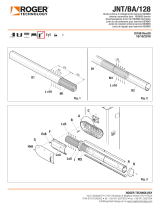
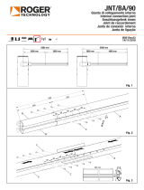
1 Installazione dell’asta
IMPORTANTE: la barriera BIONIK8 viene fornita di due aste da 4,1 m ciascuna (D1 e D2).
AVVERTENZA: per evitare danni alle superfici dei componenti, si consiglia di adagiarli su un
piano stabile e morbido.
1. Sbloccare la barriera (vedi capitolo OPERAZIONE DI SBLOCCO nel manuale di installazione
BIONIK8).
2. Ruotare il bilanciere fino a raggiungere la posizione in cui è possibile installare l’asta
orizzontalmente.
3. Bloccare nuovamente la barriera.
1.1 Preparazione asta D1 (fig. 1)
1. Rimuovere il tappo Q1 e la flangia terminale R1. Questi due particolari NON vanno più usati.
2. Sfilare il copriled N1 e accorciarlo di 285 mm dal lato di fissaggio al supporto asta.
3. Sfilare la gomma antiurto P1 e accorciarla di 285 mm dal lato di fissaggio al supporto asta.
4. Tagliare la gomma antiurto eccedente anche all’estremità opposta.
1.2 Preparazione asta D2 (fig. 2)
1. Rimuovere il tappo Q2 e la flangia terminale R2.
2. Sfilare il copriled N2 e la gomma antiurto P2. ATTENZIONE: questi due componenti NON
vanno tagliati.
1.3 Procedura di installazione
1. Inserire il giunto M1 sull’asta D1 per metà della sua lunghezza (375 mm), fig. 3.
2. Bloccare l’asta al giunto mediante le 10 viti autoforanti [L] in dotazione, 5 sopra e 5 sotto,
lungo l’asse dell’asta ogni 60 mm l’una dall’altra, fig. 3.
3. (Fig. 4) Inserire l’asta D2 sull’altra metà del giunto e bloccarla come descritto sopra.
4. L’asta così completata sarà 8,2 m di lunghezza (fig. 4).
5. Fissare la base di supporto asta [A] alla flangia [C] con le 8 viti M12x30 zincate [B] e
stringerle con forza (fig. 5).
6. Inserire il giunto M2 per tutta la sua lunghezza all’interno dell’asta.
7. Bloccare l’asta e il giunto M2 con le 10 viti autoforanti in dotazione [L], 5 sopra e 5 sotto,
lungo l’asse dell’asta ogni 60 mm l’una dall’altra, fig. 5.
8. Inserire il collarino di finitura [I] sull’asta.
9. Inserire l’asta nella sua sede nel supporto [A].
10. Posizionare la staffa di acciaio [F] e avvitare le 8 viti M10x20 zincate [E] sul supporto asta
[A], stringendole con forza.
11. Fissare la staffa [F] con 4 viti autoforanti [L], stringendole con forza.
12. Inserire sull’asta i copriled, prima N1 e poi N2 e le gomme antiurto, prima P1 e poi P2 (fig. 6).
13. Posizionare, infine, la copertura in alluminio [G] e fissarla con le 6 viti inox M8 [H], in
dotazione.
14. Riposizionare il tappo Q2 e la flangia terminale R2 fissandoli con le due viti in dotazione.
EN
1 Installing the boom
IMPORTANT: The BIONIK8 barrier is supplied with two 4.1 m booms (D1 and D2).
WARNING!: to avoid damaging the surface of the components, it is recommended to place
them on a stable and soft surface.
1. Unlock the barrier (see chapter RELEASE AND LOCK PROCEDURE in the BIONIK8
installation manual).
2. Turn the linkage lever into the position necessary for installing the boom horizontally.
3. Lock the barrier.
1.1 D1 boom preparation (fig. 1)
1. Remove the plug Q1 and the end flange R1. These two parts will NOT be used again.
2. Remove the led cover N1 and shorten it by 285 mm from the side where it is fastened to
the boom support.
3. Remove the protective rubber P1 and shorten it by 285 mm from the side where it is
fastened to the boom support.
4. Cut the excessive protective rubber at the opposite end as well.
1.2 D2 boom preparation (fig. 2)
1. Remove the plug Q2 and the end flange R2.
2. Remove the led cover N2 and the protective rubber P2. CAUTION: these two components
should NOT be cut.
1.3 Installation procedure
1. Insert the connector M1 on the boom D1 by half of its length (375 mm), fig. 3.
2. Fasten the boom to the connector using the 10 self-drilling screws [L] included, 5 above
and 5 under, along the boom axis, at a distance of 60 mm apart, fig. 3.
3. (Fig. 4) Insert the boom D2 on the other half of the connector and fasten it according to
the description above.
4. In this way, the boom will have a length of 8.2 m (fig. 4).
5. Fasten the boom support base [A] to the flange [C] with the 8 M12x30 zinc coated
screws [B] and tighten them firmly (fig. 5).
6. Insert the connector M2 completely inside the boom.
7. Fasten the boom to the connector M2 with the 10 self-drilling screws [L] included, 5
above and 5 under, along the boom axis, at a distance of 60 mm apart, fig. 5.
8. Insert the finishing collar [I] on the boom.
9. Insert the boom in its seat on the support [A].
10. Fit the steel bracket [F] and screw the 8 M10x20 zinc coated screws [E] on the boom
support [A] and tighten them firmly.
11. Fasten the bracket [F] with 4 self-drilling screws [L] and tighten them firmly.
12. Insert the led covers on the boom, first the N1 and then the N2 and then the protective
rubbers, first the P1 and then the P2 (fig. 6).
13. Lastly, fit the aluminium cover [G] and fasten it with the 6 M8 stainless steel screws [H],
included.
14. Refit the plug Q2 and the end flange R2 fastening them with the two screws included.
1 Installation des Schlagbaums
WICHTIG: die Schranke BIONIK8 wird mit zwei Schlagbäumen von jeweils 4,1 m geliefert
(D1 und D2).
HINWEIS: um Schäden an den Oberflächen der Komponenten zu vermeiden, wird empfohlen
sie auf eine stabile und weiche Fläche zu legen.
1. Die Schranke freigeben ((siehe Kapitel ENTRIEGELUNG UND VERRIEGELUNG an die
BIONIK8 Installationsanleitung).
2. Den Kipphebel drehen, bis die Position erreicht ist, in der man den Baum horizontal
montieren kann.
3. Die Schranke wieder blockieren.
1.1 D1 Schlagbaums Vorbereitung (Abb. 1)
1. Den Verschluss Q1 und den Endstückflansch R1 entfernen. Diese beiden Teile werden
NICHT mehr verwendet.
2. Die LED-Abdeckung N1 entfernen und um 285 mm von der Seite der Befestigung an der
Schlagbaumhalterung verkürzen.
3. Den stoßfestem Gummi P1 entfernen und um 285 mm von der Seite der Befestigung an
der Schlagbaumhalterung verkürzen.
4. Den überstehenden stoßfesten Gummi auch am gegenüberliegenden Ende schneiden.
1.2 D2 Schlagbaums Vorbereitung (Abb. 2)
1. Den Verschluss Q2 und den Endstückflansch R2 entfernen.
2. Die LED-Abdeckung N2 und den stoßfesten Gummi P2 entfernen. ACHTUNG: diese beiden
Komponenten werden NICHT geschnitten.
1.3 Installationsverfahren
1. Das Gelenk M1 am Schlagbaum D1 zur Hälfte seiner Länge (375 mm) einsetzen, Abb. 3.
2. Den Schlagbaum mit den 10 mitgelieferten selbstbohrenden Schrauben [L], 5 oben und
5 unten, entlang der Achse des Schlagbaums alle 60 mm eine nach der anderen, am
Gelenk befestigen, siehe Abb. 3.
3. (Abb. 12) Den Schlagbaum D2 an der anderen Hälfte des Gelenks einsetzen und wie
oben beschrieben befestigen.
4. Der fertig gestellte Schlagbaum ist 8,2 m lang (Abb. 4).
5. Die Stützbasis des Schlagbaums [A] am Flansch [C] ] mit den 8 verzinkten Schrauben
M12x30 [B] befestigen und diese fest anziehen (Abb. 5).
6. Das Gelenk M2 über seine gesamte Länge im Schlagbaum einsetzen.
7. Den Schlagbaum und das Gelenk M2 mit den 10 mitgelieferten selbstbohrenden
Schrauben [L], 5 oben und 5 unten, entlang der Achse des Schlagbaums alle 60 mm
eine nach der anderen, am Gelenk befestigen, siehe Abb. 5.
8. Die Schelle [I] am Schlagbaum einsetzen.
9. Den Schlagbaum in seinen Sitz in der Halterung [A] einsetzen.
10. Den Stahlbügel [F] positionieren und die 8 verzinkten Schrauben M10x20 [E] an der
Schlagbaumhalterung [A] anschrauben und fest anziehen.
11. Den Bügel [F] mit 4 selbstbohrenden Schrauben [L] befestigen und fest anziehen.
12. Die LED-Abdeckungen am Schlagbaum einsetzen, zuerst N1 und dann N2 sowie die
stoßfesten Gummi, zuerst P1 und dann P2 (Abb. 6).
13. Abschließend, die Aluminiumabdeckung [G] positionieren und mit den 6 mitgelieferten
Edelstahlschrauben M8 [H], befestigen.
14. Den Verschluss Q2 und den Endstückflansch R2 wieder anbringen und mit den beiden
mitgelieferten Schrauben befestigen.
IT
DE

1.3 Procedimiento de instalación
1. Introduzca la mitad de la longitud del acoplamiento M1 (375 mm) en el asta D1, fig. 3.
2. Bloquee el asta en el acoplamiento con los 10 tornillos autoperforantes [L] suministrados,
5 arriba y 5 abajo, a lo largo del eje del asta separados 60 mm uno del otro, fig. 3.
3. (Fig. 4) Introduzca el asta D2 en la otra mitad del acoplamiento y bloquéela como se
describe a continuación.
4. El asta armada de este modo tendrá 8,2 m de longitud (fig. 4).
5. Fije la base de soporte del asta [A] a la brida [C] con los 8 tornillos M12x30 galvanizados
[B] y apriételos con fuerza (fig. 5).
6. Introduzca toda la longitud del acoplamiento M2 dentro del asta.
7. Bloquee el asta y el acoplamiento M2 con los 10 tornillos autoperforantes [L]
suministrados, 5 arriba y 5 abajo, a lo largo del eje del asta separados 60 mm uno del
otro, fig. 5.
8. Monte el collar de terminación [I] en el asta.
9. Introduzca el asta en su alojamiento en el soporte [A].
10. Coloque el estribo de acero [F] y enrosque los 8 tornillos M10x20 galvanizados [E] en el
soporte del asta [A], apretándolos con fuerza.
11. Fije el estribo [F] con 4 tornillos autoperforantes [L], apretándolos con fuerza.
12. Introduzca en el asta las cubiertas de led, primero N1 y, luego, N2, y las gomas anti-
impacto, primero P1 y, luego, P2 (fig. 6).
13. Coloque, por último, la cubierta de aluminio [G] y fíjela con los 6 tornillos inox M8 [H],
suministrados.
14. Coloque nuevamente el tapón Q2 y la brida terminal R2 fijándolos con los dos tornillos
suministrados.
1 Instalação da haste
IMPORTANTE: a barreira BIONIK8 é fornecida com duas hastes de 4,1 m cada (D1 e D2).
ADVERTÊNCIA: para evitar danos às superfícies dos componentes, é aconselhável colocá-
los sobre uma superfície estável e suave.
1. Desbloqueie a barreira (veja o capítulo OPERAÇÕES DE LIBERTAÇÃO E BLOQUEIO de o
manual de instalação BIONIK8).
2. Gire o balanceiro até alcançar a posição em que é possível instalar a haste horizontalmente.
3. Bloqueie de novo a barreira.
1.1 Preparação da haste D1 (fig. 1)
1. Remova o tampão Q1 e o flange terminal R1. Estas duas peças NÃO devem ser mais
usadas.
2. Remova a cobertura do LED N1 e encurte-a 285 mm do lado de fixação para o suporte
da haste.
3. Retire a borracha antichoque P1 e encurte-a 285 mm do lado de fixação para o suporte
da haste.
4. Corte a parte excedente da borracha antichoque também na extremidade oposta.
1.2 Preparação da haste D1 (fig. 2)
• Remova o tampão Q2 e o flange terminal R2.
• Remova a cobertura do LED N2 e a borracha antichoque P2. ATENÇÃO: estes dois
componentes NÃO devem ser cortados.
1.3 Procedimento de instalação
1. Insira a junta M1 na haste D1 até metade do seu comprimento (375 mm), fig. 3.
2. Bloqueie a haste na junta usando os 10 parafusos autoperfurantes [L] fornecidos, 5
acima e 5 abaixo, ao longo do eixo da haste a cada 60 mm um do outro, fig. 3.
3. (Fig. 4) Insira a haste D2 na outra metade da junta e bloqueie-a conforme descrito acima.
4. A haste assim completada terá 8,2 m de comprimento (fig. 4).
5. Fixe a base de suporte da haste [A] ao flange [C] com os 8 parafusos M12x30
galvanizados [B] e aperte-os fortemente (fig. 5).
6. Insira a junta M2 ao longo de todo o seu comprimento dentro da haste.
7. Bloqueie a haste e a junta M2 com os 10 parafusos autoperfurantes fornecidos [L], 5
acima e 5 abaixo, ao longo do eixo da haste a cada 60 mm um do outro, fig. 5.
8. Insira o colar de acabamento [I] na haste.
9. Insira a haste na sua sede no suporte [A].
10. Posicione o suporte de aço [F] e aperte os 8 parafusos M10x20 galvanizados [E] no
suporte da haste [A], apertando-os fortemente.
11. Fixe o suporte [F] com os 4 parafusos autoperfurantes [L], apertando-os com força.
12. Insira as coberturas de LED na haste, primeiro N1 e depois N2 e as borracha antichoque,
primeiro P1 e depois P2 (fig. 6).
13. Finalmente, posicione a tampa de alumínio [G] e fixe-a com os 6 parafusos de inox M8
[H], fornecidos.
14. Reposicione o tampão Q2 e o flange terminal R2 fixando-os com os dois parafusos
fornecidos.
1 Installation de la barre
IMPORTANT : la barrière BIONIK8 est dotée de deux barres de 4,1 m chacune (D1 et D2).
AVERTISSEMENT : pour éviter des dommages aux surfaces des composants, il est
recommandé de les étendre sur un plan stable et doux.
1. Débloquer la barrière (voir chapitre OPÉRATIONS DE DÉBLOCAGE ET BLOCAGE sur le
manuel d’installation BIONIK8).
2. Tourner le balancier pour atteindre la position permettant d’installer la barre à l’horizontale.
3. Bloquer à nouveau la barrière.
1.1 Préparation de la barre D1 (fig. 1)
1. Déposer le bouchon Q1 et la bride finale R1. Ces deux pièces NE doivent PLUS être
utilisées.
2. Enlever la protection des DEL N1 et le raccourcir de 285 mm du côté de fixation au support
de la barre.
3. Enlever le caoutchouc antichoc P1 et le raccourcir de 285 mm du côté de fixation au
support de la barre.
4. Couper le caoutchouc antichoc excédent même à l’extrémité opposée.
1.2 Préparation de la barre D2 (fig. 2)
1. Déposer le bouchon Q2 et la bride finale R2.
2. Enlever la protection des DEL N2 et le caoutchouc antichoc P2. ATTENTION : ces deux
composants NE doivent PAS être coupés.
1.3 Procédure d’installation
1. Insérer le joint M1 sur la barre D1 à la moitié de sa longueur (375 mm), fig. 3.
2. Bloquer la barre au joint au moyen des 10 vis autotaraudeuses [L] fournies de série, 5
au-dessus et 5 au-dessous, au long de l’axe de la barre tous les 60 mm l’une de l’autre,
fig. 3.
3. (Fig. 4) Insérer la barre D2 sur l’autre moitié du joint et la bloquer comme décrit ci-
dessus.
4. La barre ainsi montée aura 8,2 m de longueur (fig. 4).
5. Fixer le socle de support de la barre [A] à la bride [C] avec les 8 vis M12x30 galvanisées
[B] et les serrer fermement (fig. 5).
6. Insérer le joint M2 dans toute sa longueur à l’intérieur de la barre.
7. Bloquer la barre et le joint M2 avec les 10 vis autotaraudeuses [L] fournies de série, 5
au-dessus et 5 au-dessous, au long de l’axe de la barre tous les 60 mm l’une de l’autre,
fig. 5.
8. Insérer le collier de finition [I] sur la barre.
9. Insérer la barre dans son logement sur le support [A].
10. Placer la bride en acier [F] et visser les 8 vis M10x20 galvanisées [E] sur le support de
la barre [A], les serrer ensuite fermement.
11. Fixer la bride [F] avec 4 vis autotaraudeuses [L] en les serrant fermement.
12. Insérer sur la barre les protections des DEL, d’abord N1 et puis N2 et les caoutchoucs
antichoc, d’abord P1 et puis P2 (fig. 6).
13. Placer enfin la couverture en aluminium [G] et la fixer avec les 6 vis inox M8 [H], fournies
de série.
14. Remonter le bouchon Q2 et la bride finale R2 en les fixant avec les deux vis fournies
de série.
1 Instalación del asta
IMPORTANTE: la barrera BIONIK8 se suministra con dos astas 4,1 m cada una (D1 y D2).
ADVERTENCIA: para evitar daños en las superficies de los componentes, se aconseja
colocarlos en una superficie estable y sin asperezas.
1. Desbloquee la barrera (véase sección DESBLOQUEO Y BLOQUEO en el manual de
instalación BIONIK8).
2. Gire el balancín hasta llegar a la posición en la que puede instalar la barra horizontal.
3. Vuelva a bloquear la barrera.
1.1 Preparación del asta D1 (fig. 1)
1. Retire el tapón Q1 y la brida terminal R1. Estas dos piezas NO ya no se utilizan.
2. Extraiga la cubierta de led N1 y córtela 285 mm en el lado de fijación al soporte del asta.
3. Extraiga la goma anti-impacto P1 y córtela 285 mm en el lado de fijación al soporte del
asta.
4. Corte la goma anti-impacto excedente incluso en el extremo opuesto.
1.2 Preparación del asta D2 (fig. 2)
1. Retire el tapón Q2 y la brida terminal R2.
2. Extraiga la cubierta de led N2 y la goma anti-impacto P2. ¡ATENCIÓN!: estos dos
componentes NO deben cortarse.
PT
FR
ES
-
 1
1
-
 2
2
-
 3
3
-
 4
4


Roger Technology BIONIK BOOM arm Manuale utente
- Tipo
- Manuale utente
in altre lingue
Documenti correlati
-
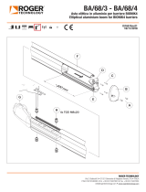
 Roger Technology JNT/BA arm Joins Manuale utente
-
 Roger Technology ALED Boom lights Istruzioni per l'uso
-
 Roger Technology BIONIK BOOM arm Manuale utente
-
 Roger Technology JNT/BA arm Joins Manuale utente
-
 Roger Technology CTRL Istruzioni per l'uso
-
Roger Technology Brushless DELUXE SET BI/008GO Manuale utente
-
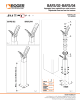 Roger Technology BAFS/01 Resting fawk Manuale utente
-
 Roger Technology BIONIK BOOM arm Manuale utente
-
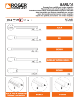 Roger Technology BAFS/01 Resting fawk Manuale utente
-
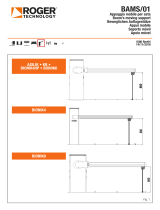 Roger Technology BAMS/01 Mobile support Manuale utente


