Baumer GIM500R - 1-dimensional Installation and Operating Instructions
- Tipo
- Installation and Operating Instructions

GIM500R - 1-dimensional/Unidirectionnelle
1 asse/1-dimensión
DE Montageanleitung
EN Assembly Instructions
FR Notice de montage
IT Istruzioni di montaggio
ES Instrucciones de montaje
Neigungssensoren
Inclination sensors
Inclinomètres
Inclinometro
Sensores de inclinación
Baumer IVO GmbH & Co. KG
Dauchinger Strasse 58-62 · DE-78056 Villingen-Schwenningen
Phone +49 7720 942-0 · Fax +49 7720 942-900
[email protected] · www.baumer.com
03.20 · 81254208 · V04 · Printed in Germany
DE
1. Allgemein
Bestimmungsgemässer Gebrauch, Inbetriebnahme, Montage, Entsorgung siehe
Beileger «Allgemeine Hinweise» (11042373).
2. Zusätzliche Informationen
Diese Montageanleitung ist eine produktspezische Ergänzung zu den allgemeinen
Dokumenten.
3. Wartung
Der Sensor ist wartungsfrei und darf nicht geöffnet beziehungsweise mechanisch
oder elektrisch verändert werden. Ein Öffnen des Sensors kann zu Verletzungen
führen.
IT
1. Generali
Istruzioni per un uso conforme, messa in funzione, montaggio, smaltimento vedi alle-
gati «Informazioni generali» (11042373).
2. Ulteriori informazioni
Queste istruzioni di montaggio sono un supplemento specico del prodotto ai docu-
menti generali.
3. Manutenzione
L‘sensor non necessita di manutenzione, non deve essere aperto e neppure essere
sottoposto a modiche meccaniche o elettriche. Un‘apertura dell‘sensor può com-
portare delle lesioni.
ES
1. General
Instrucciones para el uso adecuado, puesta en servicio, montaje, eliminación ver los
adjuntos «Información general» (11042373).
2. Información adicional
Estas instrucciones de montaje son un suplemento especíco de los documentos
generales.
3. Mantenimiento
El sensor no necesita mantenimiento. No está permitido abrirlo ni realizar cambios
mecánicos o eléctricos. Abrir el sensor puede provocar lesiones.
FR
1. Générales
Instructions pour une utilisation appropriée, Mise en service, Installation/Montage,
Éliminatión voir les annexes «Informations générales» (11042373).
2. Informations supplémentaires
Ces instructions de montage sont un complément spécique aux documents géné-
raux.
3. Maintenance
Le capteur est sans entretien et ne doit pas être ouvert ni mécaniquement ou élec-
triquement modié. En cas d‘ouverture du capteur, les ressorts risquent de provoquer
des blessures.
EN
1. General
Instructions for appropriate use, set-up, installation, disposal see insert «General
Information» (11042373).
2. Additional informations
These assembly instructions are a product-specic supplement to the general docu-
ments.
3. Maintenance
The sensor is maintenance-free and must not be opened up nor mechanically or elec-
tronically modied. Opening up the sensor can lead to injury.
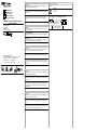
4. Technische Daten/Technical data/Caractéristiques techniques/Dati tecnici/
Especicaciones técnicas
Betriebsspannung/Voltage supply/Alimentation/Tensione d’esercizio/Tensión de servicio
8...36 VDC
R
ø
4x2x0,14 mm
2
ø = 6 mm
R x ≥45 mm
5. Schirmung am Gehäuse/Shielding on housing/Blindage sur boîtier/
Schermatura del corpo encoder/Blindaje en la carcasa
3/&
6FKLUPDQVFKOXVV
VKLHOGFRQQHFWLRQ
3RWHQWLDODXVJOHLFKVOHLWXQJ
SRWHQWLDOHTXDOL]DWLRQZLUH

6.1 GIM500R - 1-dimensional/Unidirectionnelle/1 asse/1-dimensión
6.1.1 CANopen
®
/ SAE J1939 – M12, 5-polig/5-pins/5 points
1
2
3
4
5
A-codiert/A-coded/
Codage A
1 CAN_GND
2 +Vs
3 GND
4 CAN_H
5 CAN_L
6.1.2 CANopen
®
/ SAE J1939 – 2xM12, 5-polig/5-pins/5 points
1
2
3
4
5
1
2
3
4
5
A-codiert/A-coded/
Codage A
1 CAN_GND
2 +Vs
3 GND
4 CAN_H
5 CAN_L
Klemmen mit gleicher Bezeichnung sind intern verbunden und funktionsidentisch.
Diese internen Klemmverbindungen +Vs-+Vs / GND-GND dürfen mit max. je 1 A be-
lastet werden.
Terminals of the same signicance are internally connected and identical in their functions.
Max. load on the internal terminal connections +Vs-+Vs and GND-GND is 1 A each.
Les bornes de même fonction sont reliées entre elles dans le boîtier bus. Courant
max. 1 A pour les bornes d´alimentation codeur +Vs et GND.
I morsetti con la stessa denominazione sono collegati internamente e identici nella
funzione. Questi giunti di accoppiamento interni +Vs-+Vs / GND-GND possono esse-
re sollecitati ciascuno con max. 1 A.
Los bornes con la misma designación están conectados a nivel interno y su función
es idéntica. Esas conexiones internas +Vs-+Vs / GND-GND admiten una carga máxi-
ma de 1 A cada una.
6.1.3 CANopen
®
– Kabel/Cable/Câble
Farbe/Color/Couleur
Weiss/white (wh) +Vs
Braun/brown (bn) GND
Grün/green (gn) d.u.
Gelb/yellow (ye) d.u.
Grau/grey (gy) d.u.
Rosa/pink (pk) CAN_H
Blau/blue (bu) CAN_L
Rot/red (rd) CAN_GND
6.1.4 Analog/Analogique/Analogico/Analógica – M12, 8-polig/8-pins/8 points
1
4
2
5
6
7
8
3
A-codiert/A-coded/
Codage A
1 +Vs
2 GND
3 OUT
4 d.u.
5 Teach
1)
6 d.u.
7 d.u.
8 A_GND
6.1.5 Analog/Analogique/Analogico/Analógica – Kabel/Cable/Câble
Farbe/Color/Couleur
Weiss/white (wh) +Vs
Braun/brown (bn) GND
Grün/green (gn) OUT
Gelb/yellow (ye) d.u.
Grau/grey (gy) Teach
1)
Rosa/pink (pk) d.u.
Blau/blue (bu) d.u.
Rot/red (rd) A_GND
1) Funktion Nullsetzen/Function zero setting/Function Remise à zéro
Funzione azzeramento/Función poner a cero:
Teach-Eingang für >250 ms auf HIGH Pegel (≥0,7 * +Vs) setzen / Neigung = 0°
Set Teach input for >250 ms on HIGH level (≥0.7 * +Vs) / inclination = 0°
Mettre l‘entrée Teach pendant un temps >250 ms au niveau HIGH (≥0,7 * +Vs)
pour initialiser l‘angle sur 0°
Regolare ingresso teach per >250 ms su livello HIGH (≥0,7 * +Vs) / inclinazione = 0°
Cambiar la entrada de Teach durante > 250 ms al nivel HIGH (≥0,7 * +Vs) /
inclinación = 0°
Funktion 2-Punkt-Teach/Function 2-Point-Teach/Fonction Apprentissage 2 points
Funzione teach a 2 punti/Función Teach 2 puntos:
Siehe Beschreibung Teach-Vorgang/See description Teach process
Voir la description Procédure Teach/Vedi descrizione processo teach
Ver descripción del proceso de programación (Teach)
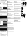
8. Montage/Mounting/Montage/Montaggio/Montaje
8.1 1-dimensional/Unidirectionnelle/1 asse/1-dimensión
3x
M4 x 25 DIN912
(1.2 Nm)
A 4.3 DIN125
8.2 Redundante Anwendung/Redundant practice (piggyback)/Appications
redondante/Applicazione ridondante/Aplicación redondante
3x M4 x 50 DIN912
(1.2 Nm)
A 4.3 DIN125
ø4.1 / ø8 mm
5 mm
6. Anschlussbelegung/Terminal assignment/Raccordement/Assegnazione dei
connettori/Patillaje del conector
DE
7. 2-Punkt-Teach (Analog)
Aktivierung
Teach-Vorgang innerhalb von 5 Minuten nach dem Einschalten starten. Teach-Ein-
gang für >5 Sekunden auf HIGH-Pegel (≥0,7 * Vs) setzen.
DUO-LED: Oszilliert nach 5 Sekunden orange.
Position 1
Neigungssensor auf die Position drehen, an der min. Spannung / Strom ausgegeben
werden soll. Teach-Eingang für >0,1 Sekunden auf HIGH setzen.
DUO-LED: Leuchtet 3 Sekunden orange und oszilliert anschliessend.
Position 2
Neigungssensor in die Position drehen, an der max. Spannung / Strom ausgegeben
werden soll. (Drehrichtung Teach-Vorgang entspricht applikativen Drehrichtung).
Teach-Eingang für >0,1 Sekunden auf HIGH-Pegel setzen.
DUO-LED: Leuchtet 3 Sekunden orange und oszilliert anschliessend 3 x grün.
Falls der Messbereich nicht eingehalten wird bzw. die Grenzen zu dicht beieinander
sind (mindestens 5° Unterschied), ist der Teach-Vorgang nicht erfolgreich (LED leuch-
tet 3 x rot) und muss wiederholt werden.
Setzen/Wiederherstellen der Werkseinstellung
Teach-Eingang für >15 Sekunden auf HIGH-Pegel setzen. DUO-LED: Oszilliert nach
5 Sekunden orange und leuchtet nach 15 Sekunden, 3 Sekunden orange.
EN
7. 2-Point-Teach (Analog)
Activate
Start teach process within 5 minutes after power on. Set teach input for >5 seconds
on HIGH level (≥0.7 * Vs).
DUO-LED: Oscillates after 5 seconds orange.
Position 1
Get inclination sensor on position intended for min. voltage output / current output.
Set teach input for >0.1 seconds on HIGH.
DUO-LED: Lights for 3 seconds orange and afterwards oscillates.
Position 2
Get encoder on position intended for max. voltage output / current output. (Direction
of rotation Teach process corresponds to application direction of rotation).
Set teach input for >0.1 seconds on HIGH.
DUO-LED: Lights for 3 seconds orange and afterwards oscillates 3 x green. If measu-
ring range is exceeded or the limits are too close to each other (min. 5° difference),
the teaching process was not successful (LED lights 3 x red) and has to be repeated.
Default
Set teach input for >15 seconds on HIGH.
DUO-LED: Oscillates after 5 seconds orange and lights after 15 seconds, 3 seconds
orange.
FR
7. Apprentissage 2 points (Analogique)
Activation de la procédure Teach
Démarrer la procédure Teach dans les 5 min après la mise sous tension. Mettre
l‘entrée Teach pendant un temps >5 secondes au niveau HIGH (≥0,7 * +Vs).
La LED clignote orange au bout de 5 secondes.
Position 1
Tourner l‘inclinomètre sur la position 1 pour laquelle la tension / le courant mini doit
être appliqué(e). Mettre l‘entrée Teach pendant un temps >0,1 seconde au niveau
HIGH. La LED s´allume pendant 3 secondes en orange puis se met à clignoter.
Position 2
Tourner l‘inclinomètre sur la position 2 pour laquelle la tension / le courant maxi doit
être appliqué(e). Mettre l‘entrée Teach pendant un temps >0,1 seconde au niveau
HIGH.
La LED s´allume pendant 3 secondes en orange puis se met à clignoter. Si la plage
de mesure n‘est pas respectée ou si les limites sont trop rapprochées l‘une de l‘autre
(au minimum 5° de différence) la procédure d‘apprentissage échouera et devra être
répétée (la LED clignote 3x en rouge).
Réglage usine
Mettre l’entrée Teach pendant un temps >15 secondes au niveau HIGH. La LED
clignote au bout de 5 secondes en orange et s‘allume après 15 secondes pendant 3
secondes en orange.
IT
7. Teach a 2 punti (analogico)
Attivazione
Avviare il processo teach entro 5 minuti dopo l‘accensione. Regolare l’ingresso teach
per >5 secondi sul livello HIGH (≥0,7 * Vs).
DUO-LED: lampeggia dopo 5 secondi in arancione.
Posizione 1
Ruotare il sensore d’inclinazione sulla posizione in cui deve essere emesso il valore
minimo di tensione / corrente. Regolare Ingresso teach per > 0,1 secondi su HIGH.
DUO-LED: si illumina in arancione per 3 secondi e poi lampeggia.
Posizione 2
Ruotare il sensore d’inclinazione sulla posizione in cui deve essere emesso il valore
massimo di tensione / corrente. (Direzione di rotazione processo teach corrisponde
alla direzione di rotazione applicativa).
Regolare ingresso teach per >0,1 secondi su livello HIGH. DUO-LED: si illumina in
arancione per 3 secondi e poi lampeggia 3 volte in verde. Qualora il campo di misu-
razione non sia rispettato o i limiti siano troppo ravvicinati (almeno 5° di differenza), il
processo teach non è effettuato correttamente (LED lampeggia 3 volte in rosso) e va
ripetuto.
Impostare/Ripristinare le impostazioni di fabbrica
Regolare ingresso teach per >15 secondi su livello HIGH. DUO-LED: lampeggia dopo
5 secondi in arancione e dopo 15 secondi si illumina per 3 secondi in arancione.
ES
7. Teach de 2 puntos (analógica)
Activación
Iniciar el proceso Teach dentro de los 5 minutos siguientes al encendido. Cambiar la
entrada de Teach durante > 5 seg. al nivel HIGH (≥0,7 * +Vs).
LED DUO: oscilante naranja tras 5 segundos.
Posición 1
Girar el sensor de inclinación a la posición en la que se deba emitir la tensión / corri-
ente mín. Cambiar la entrada de Teach durante >0,1 segundos a HIGH.
LED DUO: luz naranja 3 segundos y luego oscilante.
Posición 2
Girar el sensor de inclinación a la posición en la que se deba emitir la tensión / corri-
ente máx. (El sentido de rotación del proceso Teach equivale al sentido de rotación
en la aplicación).
Cambiar la entrada de Teach durante >0,1 segundos al nivel HIGH. LED DUO: luz
naranja 3 segundos y luego oscilante 3 veces verde. El proceso de programación
(Teach) no será correcto cuando no se pueda respetar el rango de medición o los
límites estén demasiado próximos (mínimo 5° de diferencia). En ese caso (LED 3
veces rojo), hay que repetir la programación.
Aplicar o restablecer la conguración de fábrica
Cambiar la entrada de Teach durante >15 segundos al nivel HIGH. LED DUO:
oscilante naranja tras 5 segundos y luz permanente a los 15 segundos, naranja 3
segundos.
-
 1
1
-
 2
2


Baumer GIM500R - 1-dimensional Installation and Operating Instructions
- Tipo
- Installation and Operating Instructions
in altre lingue
- français: Baumer GIM500R - 1-dimensional
- español: Baumer GIM500R - 1-dimensional
- Deutsch: Baumer GIM500R - 1-dimensional