Mettler Toledo Ultramount 0972 Manuale utente
- Tipo
- Manuale utente

15487600A
(5/99).01
0972
Ultramount
™
Weigh Modules
Service Manual

© Mettler-Toledo, Inc. 1998, 1999
No part of this manual may be reproduced or transmitted in any form or by any means, electronic or
mechanical, including photocopying and recording, for any purpose without the express written
permission of Mettler-Toledo, Inc.
U.S. Government Restricted Rights: This documentation is furnished with Restricted Rights.

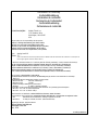
Declaration of conformity
Konformitätserklärung
Déclaration de conformité
Declaración de Conformidad
Conformiteitsverklaring
Dichiarazione di conformitá
We/Wir/Nous/Wij/Noi: Mettler-Toledo, Inc.
1150 Dearborn Drive
Worthington, Ohio 43085
USA
declare under our sole responsibility that the product,
erklären, in alleiniger Verantwortung, daß dieses Produkt,
déclarons sous notre seule responsabilité que le produit,
declaramos, bajo nuestra sola responsabilidad, que el producto,
verklaren onder onze verantwoordelijkheid, dat het product,
dichiariamo sotto nostra unica responsabilitá, che il prodotto,
Type: Analog Load Cell
Models: 777
(when used within the technical requirements listed in Mettler Toledo documentation and installed as a Load receptor as
listed in Type approval certificate T2206, Table 4.)
to which this declaration relates is in conformity with the following standard(s) or other normative document(s).
auf das sich diese Erklärung bezieht, mitder/den folgenden Norm(en) oder Richtlinie(n) übereinstimmt.
Auquel se réfère cette déclaration est conforme à la (aux) norme(s) ou au(x) document(s) normatif(s).
Al que se refiere esta declaración es conforme a la(s) norma(s) u otro(s) documento(s) normativo(s).
Waarnaar deze verklaring verwijst, aan de volende norm(en) of richtlijn(en) beantwoordt.
A cui si riferisce questa dichiarazione è conforme alla/e sequente/i norma/e o documento/i normativo/i.
CE Conformity / CE-Konformität / Conformité CE
90/384/EU Nonautomatic Balances and Scales / Nichteselbsttätige Waagen / Balances à Functionnement non automatique
Article 1.2.a.
89/336/EU EMC Directive / EMU-Richtlinie / Directive concernant la CEM
EN55 022, B: 1987 Emissions / Funkstörungen
EN50 082-2: 1995 Immunity
73/23/EU Low Voltage / Niederspannung / basse tension
EN61010-1 el. Safety / el. Sicherheit / sécurité el.
76/117/EEC concerning equipment and protective systems intended for use in potentially explosive atmospheres
EN 50 014 : 1977 + A1…A5, General requirements
EN 50 020 : 1977 + A1…A5, Intrinsic safety “i”
Other Directives and Standards / Andere Richtlinien und Normen / Autres documents
corresponding to local requirements / entsprechend lokalen Anforderungen / correspondant aux exigences locales
R60 OIML International Recommendation , Metrological regulation for load cells
EEx ib IIC T4 el. Safety / el. Sicherheit / sécurité el. (PTB Nr. Ex-98.D.2155)
Darrell Flocken, Manager - Weights & Measures
Office of Weights and Measures
Worthington, Ohio USA
May, 1999
according to EN45014

PROPRIETARY NOTICE
The information contained in this publication is derived in part from proprietary and patented data of Mettler Toledo.
This publication shall not be copied in whole or in part without prior written approval of Mettler Toledo, nor shall it
be used for any purpose other than that intended. This document is subject to change without notice.
STANDARD WARRANTY:
Model 0972 Ultramount Weigh Modules
Mettler Toledo warrants that the equipment covered by this warranty will be free from defects in workmanship and
materials for a period of one year from date of installation or eighteen (18) months from date of shipment to the
buyer, whichever comes first.
Should any such defects be found and reported during the first thirty (30) days after installation (if installation
occurs during the warranty period), Mettler Toledo (herein referred to as the “Company”), will, at its option, refund
the purchase price or correct such defects furnishing replacement parts and service free of charge to the buyer. For
the remainder of the warranty term, the Company will furnish necessary replacement parts and on-site technician’s
service free of charge, provided the Buyer agrees to pay reasonable technician’s travel time, vehicle mileage, and
associated travel expenses to and from the nearest authorized Company service location. The following are NOT
covered under any of these warranties:
1) Initial installation and ongoing scale calibration.
2) Damage to scale components by gross abuse, fire, flooding, explosion, water, voltage surges, or civil
disturbance.
3) Normal maintenance or consumable items.
This warranty covers only Model 0972 Ultramount Weigh Modules. Refer to Mettler Toledo Standard Product
Warranty for coverage of other scale system components including scale instrument, printer, and/or other
accessories.
THE COMPANY EXPRESSLY WARRANTS THE EQUIPMENT MANUFACTURED BY IT AS SET FORTH HEREIN. THE
COMPANY MAKES NO OTHER WARRANTIES EITHER EXPRESSED OR IMPLIED (INCLUDING WITHOUT LIMITATION
WARRANTIES AS TO MERCHANTABILITY OR FITNESS FOR A PARTICULAR PURPOSE). IN ADDITION, THIS DOCUMENT
SHALL CONSTITUTE THE SOLE AND EXCLUSIVE REMEDIES OF THE BUYER FOR ANY BREACH BY THE COMPANY OF
ITS WARRANTIES HEREIN.
COMPANY LIABILITY UNDER THIS WARRANTY OR ANOTHER WARRANTY WHETHER EXPRESSED OR IMPLIED IN
LAW OR FACT SHALL BE LIMITED TO THE REPAIR OR REPLACEMENT OF DEFECTIVE MATERIAL AND
WORKMANSHIP, AND IN NO EVENT SHALL IT BE LIABLE FOR CONSEQUENTIAL OR INDIRECT DAMAGES.
This warranty coverage is only applicable to the United States of America. Consult Mettler Toledo for Export
Warranty Terms and Conditions.
APPLICATION GUIDES
The only warranty of Mettler Toledo is for the product it supplies under the Product Warranty Statement listed above.
Weighing application guidelines pertain to Mettler Toledo products.

METTLER TOLEDO
Publication Revision History
An overview of this manual’s revision history is compiled below.
Publication Name: 0972 Ultramount Weigh Modules Service Manual
Publication Part Number: 15487600A Publication Date: 6/98
Part Number Date Revisions
15487600A (5/99).01
Added Declaration of Conformity.


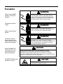
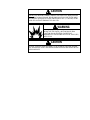
Precautions
WARNING
PERMIT ONLY QUALIFIED PERSONNEL TO SERVICE
THIS EQUIPMENT. EXERCISE CARE WHEN MAKING
CHECKS, TESTS, AND ADJUSTMENTS THAT MUST BE
MADE WITH POWER ON. FAILING TO OBSERVE THESE
PRECAUTIONS CAN RESULT IN BODILY HARM.
WARNING
FOR CONTINUED PROTECTION AGAINST SHOCK
HAZARD, CONNECT TO PROPERLY GROUNDED OUTLET
ONLY. DO NOT REMOVE THE GROUND PRONG.
WARNING
DISCONNECT ALL POWER TO THIS UNIT BEFORE
INSTALLING, SERVICING, CLEANING, OR REMOVING THE
FUSE. FAILURE TO DO SO COULD RESULT IN BODILY
HARM AND/OR PROPERTY DAMAGE.
CAUTION
BEFORE CONNECTING/DISCONNECTING ANY INTERNAL ELECTRONIC
COMPONENTS OR INTERCONNECTING WIRING BETWEEN ELECTRONIC
EQUIPMENT, ALWAYS REMOVE POWER AND WAIT AT LEAST 30 SECONDS.
FAILURE TO OBSERVE THESE PRECAUTIONS COULD RESULT IN BODILY HARM OR
DAMAGE TO OR DESTRUCTION OF THE EQUIPMENT.
CAUTION
OBSERVE PRECAUTIONS FOR HANDLING
ELECTROSTATIC SENSITIVE DEVICES.
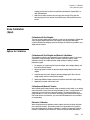
READ this manual BEFORE
operating or servicing this
equipment.
FOLLOW these instructions
carefully.
SAVE this manual for future
reference.
DO NOT allow untrained
personnel to operate, clean,
inspect, maintain, service, or
tamper with this equipment.
ALWAYS DISCONNECT this
equipment from the power
source before cleaning or
performing maintenance.
CALL METTLER TOLEDO for parts,
information, and service.

CAUTION
DO NOT PASS WELDING CURRENT THROUGH THE LOAD CELLS! WHEN WELDING
ON A SCALE, ALWAYS GROUND THE WELDING DEVICE AS CLOSE TO THE WORK
AS POSSIBLE. NEVER WELD CLOSER THAN WITHIN 4 FEET (1.2 METERS) OF ANY
LOAD CELL WITHOUT REMOVING THE LOAD CELL.
WARNING
DO NOT USE THE DigiTOL JUNCTION BOX OR IDNet
JUNCTION BOX IN LOCATIONS CLASSIFIED AS
HAZARDOUS BY THE NATIONAL ELECTRICAL CODE (NEC)
ARTICLE 500.
CAUTION
BE SURE TO BLOCK THE SCALE WHEN IT IS IN THE RAISED POSITION. OBSERVE
ALL APPROPRIATE SAFETY PROCEDURES WHEN INSTALLING AND SERVICING THE
WEIGH MODULES.

Contents
1 Specifications.........................................................................................................1-1
Ultramount Weigh Modules.................................................................................................1-1
Model Number....................................................................................................................1-2
Load Cells and Suspension..................................................................................................1-2
Power Supply Requirements................................................................................................1-4
Accuracy............................................................................................................................1-4
2 Inspection and Site Selection...................................................................................2-1
Inspection..........................................................................................................................2-1
Site Selection.....................................................................................................................2-1
3 Installation .............................................................................................................3-1
Installation.........................................................................................................................3-1
Modes of Operation ............................................................................................................3-4
Analog Mode.......................................................................................................................3-4
DigiTOL DLC Mode...............................................................................................................3-5
IDNet Mode.........................................................................................................................3-6
Home Run Cable Connection...............................................................................................3-8
4 Calibration..............................................................................................................4-1
Shift Adjust ........................................................................................................................4-1
Analog Junction Box Shift Adjustment......................................................................................4-1
DigiTOL Junction Box Shift Adjustment ....................................................................................4-2
IDNet Junction Box Shift Adjustment........................................................................................4-2
Scale Calibration (Span).....................................................................................................4-3
Options for Calibration..........................................................................................................4-3
5 Routine Care and Maintenance................................................................................5-1
General..............................................................................................................................5-1
Site Inspection ...................................................................................................................5-1
Weigh Module and Junction Box Inspection .........................................................................5-1
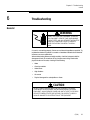
6 Troubleshooting ......................................................................................................6-1
General..............................................................................................................................6-1
Isolate the Problem ............................................................................................................6-2
Check Wiring......................................................................................................................6-2
Check Load Cells................................................................................................................6-3
Check Mechanical Components...........................................................................................6-4
Load Cell Replacement Procedure .......................................................................................6-4
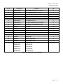
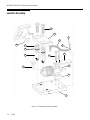
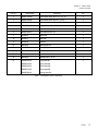
7 Service Parts ..........................................................................................................7-1
Ball-and-Cup Assembly.......................................................................................................7-2
Load-Pin Assembly .............................................................................................................7-4

8 Reference Material..................................................................................................8-1
Reference Drawings............................................................................................................8-1
Recommended Spare Parts .................................................................................................8-1

Chapter 1: Specifications
Ultramount Weigh Modules
(5/99)
1-1
1 Specifications
Ultramount Weigh
Modules
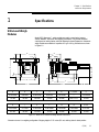
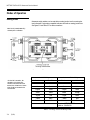
Model 0972 Ultramount™ weigh modules are used to convert tanks, hoppers,
vessels, blenders, and mixers into weighing instruments. They provide horizontal
checking and an anti-tip feature, while still allowing for thermal expansion. Ultramount
weigh modules are available in capacities of 5 kg to 100 kg. Dimensions are shown
in Figure 1-1.
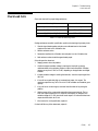
A B C D E* F Thread G
2.76 inches 0.62 inch 4.00 inches 0.50 inch 3.15 inches -- 2.19 inches
70 mm 16 mm 102 mm 13 mm 80 mm M12 x 1.75 56 mm
H J K L M N O Dia.
1.65 inches 0.71 inch 5.19 inches 2.99 inches 1.94 inches 1.64 inches 0.41 inch
42 mm 18 mm 132 mm 76 mm 49 mm 42 mm 10 mm
Figure 1-1: Model 0972 Ultramount Weigh Module Dimensions
*Dimension shown is in weighing configuration. Shipping height is 3.23 inches (82 mm) with top plate in raised position.
A
F
A
B
D
E
D
B
C
G
H
J
H
K
L
O
N
M

METTLER TOLEDO 0972 Ultramount Service Manual
(5/99)
1-2
Model Number
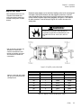
Table 1-1 shows how to use the model number to determine the proper load cell
configuration for Ultramount weigh modules.
Model Number Configuration
XXXX X X X X XX -X
Model Weigh
Module
Type
Cell Type # Load Cells # of
Modules
Cell Capacity Junction Box
0972 0 = None 0 = Pin (Static)
1 = Ball & Cup
(Dynamic)
0 = Dummy Load Cell
1 = 5kd NIST H44
2 = 3kd OIML
1, 3, or 4 X5 = 5 kg
01 = 10 kg
02 = 20 kg
05 = 50 kg
10 = 100 kg
1 = Analog J-Box
2 = No J-Box
Table 1-1: Load Cell Configuration
Load Cells and
Suspension
Model number: 777 Load Cells, 5 kg, 10 kg,
20 kg, 50 kg, 100 kg
Maximum excitation voltage: 18 VDC maximum
Recommended excitation voltage: 10 VDC
Full-scale output: 2 mV/V
Input terminal resistance: 350 to 480 ohms minimum
Output terminal resistance: 356 ± 0.12 ohms
Temperature range compensation: -10°C to +40°C
(+14°F to 104°F)
Safe side load: 100% of full load cell rating
Safe overload: 150% of full load cell rating
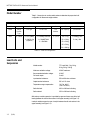
Ball-and-cup module suspension is provided by upper and lower cups with a ball
bearing between the cell and the receiver in the upper assembly (see Figure 1-2).
Load-pin module suspension uses a load pin between the cell and receiver in the
upper assembly (see Figure 1-3).

Chapter 1: Specifications
Load Cells and Suspension
(5/99)
1-3
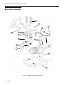
Figure 1-2: Ball-and-Cup Assembly
Figure 1-3: Load-Pin Assembly
Top Plate
Load Pin
Load Cell
Base Plate
Top Plate
Load Cell
Base Plate
Ball and Cup

METTLER TOLEDO 0972 Ultramount Service Manual
(5/99)
1-4
Power Supply
Requirements
A METTLER TOLEDO digital indicator is used to power the analog load cells in Model
0972 Ultramount weigh modules. The type of digital indicator that is used determines
which type of junction box (Analog, DigiTOL, or IDNet) is required for the weigh
modules.
Refer to the digital indicator’s service manual for the indicator’s power requirements.
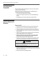
Accuracy
Scale accuracy depends on:
• The design of the support steel for the module and of the receiving structure (tank,
hopper, conveyor, etc.) mounted to the modules
• The design and number of dead-to-live connections attached to the scale
• The total load cell capacity
• Environmental factors: wind, vibration, temperature variations, etc.
Refer to METTLER TOLEDO Weigh Module Systems Handbook *15598500A for
assistance.
* May have an alphabetical prefix.

Chapter 2: Inspection and Site Selection
Inspection
(5/99)
2-1
2 Inspection and Site Selection
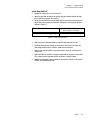
Inspection
When you receive your weigh modules, visually inspect the packing containers and
modules for freight damage. Inspect:
1. Load cell and suspension assemblies
2. Load cell cables and summing junction box
3. Overall assembly
If you find damage, contact your freight carrier immediately. Fill out the enclosed
warranty card and return the weigh module to the address indicated.
Site Selection
Problems installing weigh modules are often caused by inappropriate site conditions.
Before installing the weigh modules, check the site for:
• Level support surfaces to within 1/8 inch (3.2 mm), highest to lowest location
• Adequate support, where each module meets the floor or structure, throughout the
scale’s weighing capacity
• Uniform deflection of the weigh module supports (top and bottom), maintaining
less than one-half degree out of level at gross capacity
• Proper drainage away from each of the weigh modules
• Heavy vibrations or wind currents at or near the scale
• Access around each weigh module for installation and service
• Locations on the scale to add test weights for calibration
• Access to the scale for moving test weights to the scale’s loading locations
• A position near the proposed scale location to mount the junction box
(Do not mount the junction box on the live portion of the scale.)
• Excessive or unusual loading caused by the site or type of equipment mounted to
the weigh modules
• Shared foundation: Does the vessel to be weighed have an exclusive, isolated
support foundation? Does it share supports with other vessels? Interaction may
occur if the vessel is on a shared foundation
If the site is appropriate based on the criteria above, proceed with the installation.
Otherwise, make necessary adjustments before installing the modules.

Chapter 3: Installation
Installation
(5/99)
3-1
3 Installation
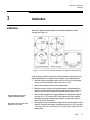
Installation
Model 0972 Ultramount weigh modules can be oriented for tangential or radial
mounting (see Figure 3-1).
Figure 3-1: Plan View of Mounting Arrangements for Ultramount Weigh Modules
Install the weigh modules according to the following instructions. Make provisions for
required adjustments on the weigh structure to maintain correct module alignment:
1. Level each module’s base plate to within ±1/32 inch (0.8 mm). All base plates
must be on the same level plane within ±1/16 inch (1.6 mm).
2. Slowly lower the weigh structure onto the weigh modules.
3. Make sure that each load point on the weigh structure is well supported by the
module’s top plate, and that all top plates are level within ±1/32 inch (0.8 mm).
Otherwise, shim until each load point is supported and the top plate is level.
4. Bolt or weld the top plates of the weigh modules to the weigh structure supports,
using two M12 x 1.75 screws or 3/8-16 UNC bolts and nuts. Bolt or weld the
base plates of the weigh modules to the foundation or support steel, using four
M10 or 3/8-16 UNC anchor bolts.
5. If the top plates are to be welded to the weigh structure or the base plates are to be
welded to a structural steel support, the weld should be 3/16 inch (4.8 mm) fillet,
1 inch long (25.4 mm), and 3 inches (76.2 mm) pitch with 2 inches (50.8 mm)
between welds.
Note: Mounting plate bolts are not
supplied by METTLER TOLEDO.
Note: Always remove load cells when
welding top or base plates.

METTLER TOLEDO 0972 Ultramount Service Manual
(5/99)
3-2
CAUTION
DO NOT PASS WELDING CURRENT THROUGH THE LOAD CELLS! WHEN
WELDING ON A SCALE, ALWAYS GROUND THE WELDING DEVICE AS
CLOSE TO THE WORK AS POSSIBLE. NEVER WELD CLOSER THAN WITHIN 4
FEET (1.2 METERS) OF ANY LOAD CELL WITHOUT REMOVING THE LOAD
CELL.
6. After securing all the top plates and base plates, slowly back out the nut and
centering washer on the hold-down bolt, carefully lowering the top plate and weigh
structure onto the load cells.
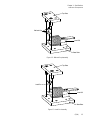
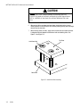
7. After all the top plates are down, apply load to the load cells and make sure there
is adequate clearance between the hold-down bolts and retaining holes. See
Figure 3-2 and Figure 3-3.
Figure 3-2: Hold-Down Bolt Assembly
Hold-Down Bolt
Top Plate
Base Plate

Chapter 3: Installation
Installation
(5/99)
3-3
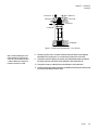
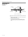
Figure 3-3: Hold-Down Bolt Assembly - Cross Section
8.
Mount the junction box in a location where the load cell cables can be properly
terminated in the junction box. Do not mount the junction box on the scale.
9. Connect the load cell cables to the junction box and terminate wires according to
the wiring and color code decal on the underside of the junction box lid.
10. Connect the home run cable from the scale indicator to the junction box.
11. Confirm that all live-to-dead connections are flexible and securely anchored at both
the scale and the dead connection point.
Top Plate
Clearance
Clearance
Clearance
Baseplate
Clearance
Clearance
Note: Consider calibrating the scale
before connecting any piping to the
scale. The scale can then be used as
a meter to determine if a proper live-
to-dead connection was made.

METTLER TOLEDO 0972 Ultramount Service Manual
(5/99)
3-4
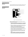
Modes of Operation
Analog Mode
Ultramount weigh modules can be used with an analog junction box for summing the
load cell outputs. Only analog-compatible indicators work with an analog junction box.
See Figure 3-4 and Table 3-1 for cable connections.
Figure 3-4: Analog Junction Box Detail
Load Cell Wiring Instrument Cable Wiring
Function Wire Color Function Color
+ Excitation Blue + Excitation White
+ Sense Green* + Sense Yellow
+ Signal White + Signal Green
Shield Yellow Shield Orange
- Signal Red - Signal Black
- Sense Gray* - Sense Red
- Excitation Black - Excitation Blue
Based on METTLER TOLEDO
cable no. 510624370
Table 3-1: Analog Junction Box Wiring Codes
Note: Turn all potentiometers fully
clockwise prior to calibration.
*For load cell connections, the
+Excitation and +Sense wires
should be connected to the same
terminal; the -Excitation and -Sense
wires should be connected to the
same terminal.
+EXC/
+SE
N
+SI
G
SHL
D
-SIG
-SE
N/
-EX
C
+EXC/
+SE
N
+SI
G
SHL
D
-SIG
-SE
N/
-EX
C
EXC/
SE
N
SI
G
HL
D
SIG
SE
N/
EX
C
+EXC/
+S
EN
+S
IG
SH
LD
-SI
G
-SE
N/
-EX
C

Chapter 3: Installation
Modes of Operation
(5/99)
3-5
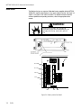
DigiTOL DLC Mode
Ultramount weigh modules can be used with a DigiTOL junction box for summing load
cell outputs. Only DigiTOL indicators work with a DigiTOL junction box. In the DLC
mode, the indicator serves as the host for the DigiTOL junction box, allowing you to
use the indicator’s keypad to adjust scale parameters. See Figure 3-5 and Table 3-2
for cable connections. Load cell wiring for DigiTOL DLC mode is the same as for
analog mode.
WARNING!
DO NOT USE THE DigiTOL JUNCTION BOX IN
LOCATIONS CLASSIFIED AS HAZARDOUS BY THE
NATIONAL ELECTRICAL CODE (NEC) ARTICLE
500.
Figure 3-5: DigiTOL Junction Box Detail
Terminal No. Position Function Wire Colors
TB2 10 +20 VDC Green
TB2 12 Ground Blue
TB1 1 Shield Orange
TB1 2 RXD A Red
TB1 3 RXD B White
TB1 4 TXD B Yellow
TB1 5 TXD A Black
Table 3-2: DigiTOL Junction Box Wiring DLC Mode
Note: The DigiTOL junction box is not
compatible with the Model 8510
panel mount indicator, Models 8572
and 8582 counting scales, or Model
8530VS.
Note: For 2 mV/V load cells, jumpers
W1, W2, W3, and W4 must be ON
(shorting the pins).
Note: For load cell connections, the
+Excitation and +Sense wires
should be connected to the same
terminal; the -Excitation and -Sense
wires should be connected to the
same terminal.
La pagina si sta caricando...
La pagina si sta caricando...
La pagina si sta caricando...
La pagina si sta caricando...
La pagina si sta caricando...
La pagina si sta caricando...
La pagina si sta caricando...
La pagina si sta caricando...
La pagina si sta caricando...
La pagina si sta caricando...
La pagina si sta caricando...
La pagina si sta caricando...
La pagina si sta caricando...
La pagina si sta caricando...
La pagina si sta caricando...
La pagina si sta caricando...
La pagina si sta caricando...
La pagina si sta caricando...
La pagina si sta caricando...
La pagina si sta caricando...
La pagina si sta caricando...
-
 1
1
-
 2
2
-
 3
3
-
 4
4
-
 5
5
-
 6
6
-
 7
7
-
 8
8
-
 9
9
-
 10
10
-
 11
11
-
 12
12
-
 13
13
-
 14
14
-
 15
15
-
 16
16
-
 17
17
-
 18
18
-
 19
19
-
 20
20
-
 21
21
-
 22
22
-
 23
23
-
 24
24
-
 25
25
-
 26
26
-
 27
27
-
 28
28
-
 29
29
-
 30
30
-
 31
31
-
 32
32
-
 33
33
-
 34
34
-
 35
35
-
 36
36
-
 37
37
-
 38
38
-
 39
39
-
 40
40
-
 41
41


Mettler Toledo Ultramount 0972 Manuale utente
- Tipo
- Manuale utente
in altre lingue
Documenti correlati
-
Mettler Toledo IND780 (11 MB) Guida d'installazione
-
-
-
-
-
-
-
-
-