Lutron Electronics QSGRK-16D Quick Installation And Operation Manual

Tipo
Quick Installation And Operation Manual

Questo manuale è adatto anche per

LUTRON
with DALI
Quick Installation
and Operation
Guide
®
Please Read
The GRAFIK Eye QS with DALI control unit allows for control of both lights
and window treatments, without interfaces, using a single control unit.
Features include pushbutton scene recall, info screen that displays energy
savings and status, IR receiver, astronomic timeclock, contact closure input,
and engravable backlit buttons that are easy to find and operate. The built-in
DALI bus link can control up to 64 DALIdevices.
Model Numbers: QSGRK-6D, QSGRK-8D, QSGRK-16D
QSGR-6D, QSGR-8D, QSGR-16D
QSGRM-6D, QSGRM-8D, QSGRM-16D
Ratings: 100 - 240 V 50/60 Hz 100 mA
CE 230 V 50/60 Hz 100 mA
Output: PELV (Class 2: USA) supply 24 V 150 mA
DALI Link: 18 V 250 mA
Contents
Features and Functions. . . . . . . . . . . . . . . . . . . . . . . 2
Wiring the GRAFIK Eye® QS with DALI
Overview of Line Voltage/Mains
and DALI Wiring . . . . . . . . . . . . . . . . . . . . . . . . . 3
Line Voltage Wiring Details. . . . . . . . . . . . . . . . . . 4
DALI Bus Wiring Details . . . . . . . . . . . . . . . . . . . . 5
Overview of PELV (Class 2: USA) Wiring . . . . . . . 6
QS Link Control Wiring Details. . . . . . . . . . . . . . . 7
Completing Installation . . . . . . . . . . . . . . . . . . 8
Programming Mode . . . . . . . . . . . . . . . . . . . . . . . 9
Wireless Mode. . . . . . . . . . . . . . . . . . . . . . . . .10
Zone Setup . . . . . . . . . . . . . . . . . . . . . . . . . . . . . . 11
DALI Setup Overview: Build System . . . . . . . . . 12
DALI Setup . . . . . . . . . . . . . . . . . . . . . . . . . . . . . . 13
Associating Wireless Occupancy Sensors . .14
Occupancy Sensor Setup: Scene Mode . . . . . 15
Associating Wireless Daylight Sensors . . . . .16
Daylight Sensor Setup
Mode Assignment . . . . . . . . . . . . . . . . . . . . . . . . 17
Zone Mode . . . . . . . . . . . . . . . . . . . . . . . . . . . . . 18
Group Mode . . . . . . . . . . . . . . . . . . . . . . . . . . . . 19
Scene Setup . . . . . . . . . . . . . . . . . . . . . . . . . . . . . 21
Troubleshooting . . . . . . . . . . . . . . . . . . . . . . .22
Troubleshooting: DALI Functions . . . . . . . . . .23
Warranty, Contact Information . . . . . . . . . . . .24
For additional information, see the complete 
installation and operation guide at 
www.lutron.com/qs
English
Español Italiano
Français Deutsch
OK
1 2
3
4
5
69 10
11 12
13
14
7
815 16
9-16
1-8
Info screen
Displays status or
programming functions
Scene buttons
With integral scene
indicator LEDs
Optional Shade
(window treatment) button
groups
Preset and raise/lower
buttons with integral LEDs
(maximum of 3 button
groups)
Zone numbers
Zone raise/lower buttons
Zone LEDs display current
lighting zone levels
Timeclock button
Displays current
timeclock info
OK button
Used for programming,
fade time
Infrared receiver
For handheld remote use
Master buttons
Temporarily raise and lower
lighting levels on unit
USB type mini B
For programming via PC
{
Hinged faceplate
Hinged faceplate
Features and Functions of the GRAFIK Eye® QS with DALI
Page button
Switches between displaying
zones 1 to 8 and 9 to 16 on
16-zone unit
Note: 6-zone control unit will show only zones 1 through 6.
®
GRAFIK Eye® QS with DALI Quick Installation and Operation Guide 2
For additional information, see the complete installation and operation guide at www.lutron.com/qs
®
GRAFIK Eye® QS with DALI Quick Installation and Operation Guide 3
For additional information, see the complete installation and operation guide at www.lutron.com/qs
Wiring the GRAFIK Eye® QS with DALI:
Overview of Line Voltage/Mains and DALI Wiring
4,0 mm
2
(12 AWG)
each terminal
100 240 V
50 / 60 Hz
Distribution
Panel
Line Voltage/Mains
Cables and Load Wiring
D2
D1
D2
D1
To additional DALI
devices
DALI Bus Wiring
(See page 5 for complete wiring
specification)
Two 1,5 mm
2
(16 AWG)
each terminal
DALI devices: ballasts,
drivers, or interfaces
Two D1 and two D2 connections are
provided for ease of wiring, and to
provide two connecting points; there is
only one DALI link on the unit.
Note: Ballasts and other DALI devices
must NOT obtain power from a line
voltage output on the GRAFIK  Eye QS
with DALI.
Distribution
Panel
L
N
L
N
Terminal labels:
L: Hot/Live
N: Neutral
: Ground
Wiring the GRAFIK Eye® QS with DALI:
Line Voltage Wiring Details
Use properly certified cable for all line
voltage/mains cables.
Proper short-circuit and overload
protection must be provided at the
distribution panel.
Install in accordance with all local and
national electrical codes.
PELV (Class 2: USA) terminals may be
temporarily unplugged for ease of IR,
occupancy sensor, and control wiring.
Notice: Risk of damage to unit. Do not
connect line voltage/mains cable to PELV
(Class 2: USA) terminals.
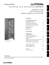
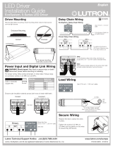
Step 1: Install wallbox. Mount an 89 mm
(3,5 in) deep 4-gang U.S. wallbox on a
dry, flat indoor surface that is accessible
and allows for system programming and
operation. Allow at least 110 mm (4,5 in)
clearance above and below the faceplate
to ensure proper heat dissipation. Allow
25 mm (1 in) for faceplate overhang on
all sides.
Note: 4-gang wallbox available from
Lutron; P/N 241400.
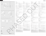
Step 2: Check control unit wiring.
Earth/ground terminal connection must
be made as shown in wiring diagrams
(see page 3).
Do not mix different load types on the
same zone.
Follow all local and national electrical
codes when installing PELV (Class 2:
USA) wiring with line voltage/mains wiring.
WARNING! Shock hazard. May
result in serious injury or death.
Always turn off circuit breaker or
remove main fuse from power
line before doing any work.
Before connecting the loads to
the GRAFIK Eye QS with DALI
control unit, test the loads for
short-circuits.
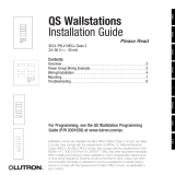
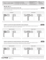
Step 3: Connect line voltage and loads
to control unit.
Strip 8 mm (5/16 in) of insulation off the
line voltage/mains cables in the wallbox.
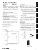
Connect the line voltage/mains, ground,
and load wires to the appropriate
terminals on the back of the control unit.
L: Hot/Live
N: Neutral
: Ground
The recommended installation torque is
0,6 N∙m (5,0 in∙lbs) for line voltage/mains
connections and 0,6 N∙m (5,0 in∙lbs) for
the earth/ground connection.
Notice: Risk of damage to unit.
GRAFIK Eye QS with DALI control
units must be in stalled by a qual i fied
electrician in accordance with all applica-
ble reg u la tions and building codes.
Im prop er wiring can result in dam age to
control units or oth er equipment.
Note: To avoid over heat ing and pos-
si ble damage to equipment, do not
install control units to dim re cep ta cles,
mo tor-op erated ap pli ances, or flu o res-
cent lighting not equipped with DALI
electron ic dim ming ballasts, or other
DALIdevices approved for your location.
Control units are de signed for res i den tial
and commercial use, for indoor use only.
LUTRON
LUTRON
Faceplate overhangs
wallbox on all sides;
allow 25 mm (1 in)
110 mm
(4,5 in)
8 mm
(5/16 in)
®
GRAFIK Eye® QS with DALI Quick Installation and Operation Guide 4
For additional information, see the complete installation and operation guide at www.lutron.com/qs
®
GRAFIK Eye® QS with DALI Quick Installation and Operation Guide 5
For additional information, see the complete installation and operation guide at www.lutron.com/qs
DALI bus wiring may be considered
NEC® Class 1 or PELV (Class 2: USA).
NEC® Class 1: DALIbus wiring may be
run in the same conduit as mains voltage
wiring to fixtures.
PELV (Class 2: USA): DALIbus wiring
must be separated from all mains and
NEC® Class 1 wiring.
Consult applicable national and local
codes for compliance.
Lutron recommends using two different
colours for D1 and D2 (DALIbus) wires.
This will prevent wiring mistakes in
junction boxes where several different
DALIbuswires combine. Use the
following instructions for wiring the DALI
bus.
Each DALIlink can have only 1 GRAFIK 
Eye QS with DALI connected to it. No
additional DALI bus supplies can be on
the link.
Up to 64 DALI devices can be connected
to the DALIlink.
No other devices may be connected to
the DALIlink.
WARNING! Shock hazard.
May result in serious injury or
death.
Do not wire live. Interrupt
power via circuit breaker before
wiring and servicing the DALI bus
supply.
Step 1: Use the wire size chart at right to
determine which wire size to use based
on the length of the DALIbus.
Step 2: Wire the DALIbus from terminal
D1 and terminal D2 to all DALI devices.
Step 3: Separate DALI wiring from the
mains wiring. If wiring the DALIbus as
PELV (Class 2: USA), maintain proper
separation from mains and NEC® Class 1
wiring.
Step 4: Turn on circuit breaker to
energise.
DALI Bus
18 V
250 mA
Wiring the GRAFIK Eye® QS with DALI:
DALI Bus Wiring Details
Wiring Size and Bus Length
DALIbus wires D1 and D2 are not
polarity sensitive. DALI bus length is
limited by the wire gauge used for D1 and
D2 as follows:
Wire Gauge Maximum DALI Bus
Length
4,0 mm
2
12 AWG
671 m
2 200 ft
2,5 mm
2
14 AWG
427 m
1 400 ft
1,5 mm
2
16 AWG
275 m
900 ft
1,0 mm
2
18 AWG
175 m
570 ft
DALI bus wiring cables (1,5 mm
2
/
16 AWG) are available from Lutron, part
numbers C-CBL-216-GR-1 (non-plenum)
and C-PCBL-216-CL-1 (plenum).
Contact Closure Input Wiring
For settings, see complete installation and
operation guide at www.lutron.com/qs.
1 2
A B C
N H 1 2 3 4 5 6
1 2 3 4
1 2 3 4
1 2
A B C
1 2 3 4 5 6 L N
1 2 3 4
1 2
A B C
1 2 3 4 5 6 L N
Note: Use appropriate wire connecting devices
as specified by local codes.
Example:
Occupancy sensor
(maximum 1)
1: COM
2: 24 V *
3: MUX
4: MUX
Control Wiring
Wiring the GRAFIK Eye® QS with DALI:
Overview of PELV (Class 2: USA) Wiring
IR Wiring
From external
IR connection
(by others)
1,0 mm
2
(18 AWG)
each terminal
1,0 mm
2
(18 AWG)
each terminal
1: IR DATA
2: IR COM
A: CCI SIG
B: 24 V
C: CCI COM
To control stations,
window treatments,
or other GRAFIK Eye
QS control units
Data (terminals 3 and 4):
Twisted, shielded pair 0,5 mm
2
(22 AWG)
each terminal
Common and power (terminals 1 and 2):
Two 1,0 mm
2
(18 AWG) each terminal
* Do not connect terminal 2
between any GRAFIK Eye QS
and any other power supply,
including another
GRAFIK Eye
QS. See complete installation
and operation guide at www.
lutron.com/qs. for detailed wiring
example.
®
GRAFIK Eye® QS with DALI Quick Installation and Operation Guide 6
For additional information, see the complete installation and operation guide at www.lutron.com/qs
System communication uses PELV (Class 2: USA)
wiring.
Follow all local and national electrical codes when
installing PELV (Class 2: USA) wiring with line
voltage/mains wiring.
Each terminal accepts up to two 1,0 mm
2
(18 AWG)
wires.
Total length of control link must not exceed
610 m (2 000 feet).
Make all connections in the control unit’s wallbox.
Wiring can be T-tapped or daisy-chained.
Wire sizes:
- Two 1,0 mm
2
(18 AWG) conductors for control
power.
- One twisted, shielded pair of 0,5 mm
2
(22 AWG) for
data link.
- Cable is available from Lutron:
GRX-CBL-346S-500 (non-plenum) and
GRX-PCBL-346S-500 (plenum). Check
compatibility in your area.
PELV (Class 2: USA) 24 V 150 mA.
QS smart
power
panel
LUTRON
LUTRON
LUTRON
LUTRONLUTRON
LUTRON
LUTRON
LUTRON
LUTRON
LUTRON
LUTRON
LUTRON
T-Tap Wiring Example
GRAFIK Eye QS
with DALI
Sivoia QS
seeTouch QS
Wiring the GRAFIK Eye® QS with DALI:
QS Link Control Wiring Details
To DALI link 1
To DALI link 2
System Limits
The QS wired communication link is limited to 100 devices or 100 zones. Please
note the zone count and power draw unit information in the following table.
QS Device Zone
Count
Power Draw Units
(supplied)
Power Draw
Units (consumed)
3-zone
GRAFIK Eye QS 3 3 0
4-zone
GRAFIK Eye QS 4 3 0
6-zone
GRAFIK Eye QS 6 3 0
8-zone
GRAFIK Eye QS 8 3 0
16-zone
GRAFIK Eye QS 16 3 0
seeTouch
® QS 0 0 1
International seeTouch
®
QS
0 0 1
Sivoia
® QS 1 0 (Refer to Spec.
Submittal)
Contact closure interface 5 0 3
Network interface 0 0 2
DMX interface 0 0 2
QS smart power panel 0 (Refer to Spec.
Submittal)
0
QS link power supply 0 8 0
LUTRON
LUTRON
LUTRON
LUTRONLUTRON
LUTRON
LUTRON
LUTRON
LUTRON
LUTRON
LUTRON LUTRON LUTRON
LUTRON
LUTRON
LUTRON
LUTRON
LUTRONLUTRON
LUTRON
LUTRON
LUTRON
LUTRON
LUTRON
LUTRON LUTRON LUTRON
LUTRON
LUTRON
LUTRON
LUTRON
LUTRON
LUTRON
LUTRON
LUTRON
LUTRON
LUTRON
LUTRON
LUTRON LUTRON LUTRON
LUTRON
LUTRON
LUTRON
LUTRON
LUTRONLUTRON
LUTRON
LUTRON
LUTRON
LUTRON
LUTRON
LUTRON LUTRON LUTRON
LUTRON
LUTRON
LUTRON
LUTRON
LUTRONLUTRON
LUTRON
LUTRON
LUTRON
LUTRON
LUTRON
LUTRON
LUTRON
GRAFIK Eye QS
with DALI
Sivoia
QS
seeTouch QS
Daisy-Chain Wiring Example
QS smart
power panel
To DALI link 2To DALI link 1
GRAFIK Eye QS
with DALI
LUTRON
LUTRON
LUTRON
LUTRONLUTRON
LUTRON
LUTRON
LUTRON
LUTRON
LUTRON
LUTRON LUTRON LUTRON
LUTRON
LUTRON
LUTRON
LUTRON
LUTRONLUTRON
LUTRON
LUTRON
LUTRON
LUTRON
LUTRON
LUTRON LUTRON LUTRON
LUTRON
LUTRON
LUTRON
LUTRON
LUTRONLUTRON
LUTRON
LUTRON
LUTRON
LUTRON
LUTRON
LUTRON LUTRON LUTRON
LUTRON
®
GRAFIK Eye® QS with DALI Quick Installation and Operation Guide 7
For additional information, see the complete installation and operation guide at www.lutron.com/qs
Completing Installation of the GRAFIK Eye® QS with DALI
1. Mount the control unit in the wallbox as
shown using the four screws pro vid ed.
Note: Follow all local and national
electrical codes when installing PELV
(Class 2: USA) wiring with line voltage/
mains wiring.
2. Verify installation:
Restore power.
Press the top scene button. The LED will
light.
Press the zone raise or lower button.
Make sure the control unit is dimming all
connected loads.
3. Apply the protective overlay to the control
unit. See the complete installation and
operation guide at www.lutron.com for
instructions for naming zones.
Note: When tightening mounting
screws, make sure that the hinged
cover and faceplate will open fully,
as shown.
Wall
7,9 in
(200 mm)
3,5 in
(87 mm)
3,75 in
(95 mm)
Protective overlay
(apply after installation)
®
GRAFIK Eye® QS with DALI Quick Installation and Operation Guide 8
For additional information, see the complete installation and operation guide at www.lutron.com/qs
Entering and Exiting Programming Mode
To enter programming mode:
Press and hold the top and bottom scene
buttons simultaneously for 3 seconds. The
LEDs in the scene buttons will scroll from
top to bottom, confirming that you are in
programming mode, and the info screen will
display the main menu.
To exit programming mode:
Press and hold the top and bottom scene
buttons simultaneously for 3 seconds. The
info screen will go to Scene 1.
Navigating Menus in Programming Mode
Master Buttons
The Master buttons allow you to move through the menu
choices. The current choice is highlighted on the info screen.
OK Button
The OK button chooses the current highlighted menu choice.
This will either take you to the next menu or accept a setting you
have selected. When the screen displays a Yes/No question, the
OK button is “Yes”.
Timeclock Button
The timeclock button functions as a “back” button during
programming mode. Pressing the timeclock button takes you
back one step in the current menu. Pressing it repeatedly
will eventually return you to the main menu, but will not exit
programming mode. When the screen displays a Yes/No
question, the Timeclock button is “No”.
Programming Mode
OK
1 2
3
4
5
69 10
11 12
13
14
7
815
16
9-16
1-8
Press and hold the top and
bottom buttons for 3 seconds
to enter or exit programming
mode
Master buttons
OK button
Timeclock (back) button
Main menu
Scene setup
Timeclock
Scene 1
Fade time
3 seconds
®
GRAFIK Eye® QS with DALI Quick Installation and Operation Guide 9
For additional information, see the complete installation and operation guide at www.lutron.com/qs
®
GRAFIK Eye® QS with DALI Quick Installation and Operation Guide 10
For additional information, see the complete installation and operation guide at www.lutron.com/qs
Wireless Mode
Many models of the GRAFIK Eye® QS support wireless communication with other
Lutron products. This feature allows for easy integration of wireless sensors, keypads,
remotes, and window treatments for single-room wireless applications, as well as
compatibility with other Lutron wireless systems.
Units supporting wireless communication have model numbers beginning with QSGRJ,
QSGRK, or QSGRM.
The wireless feature of the GRAFIK  Eye QS Wireless control unit has three (3) modes of
operation.
Disabled: Use for wired-only systems.
Enabled: The GRAFIK Eye QS Wireless control unit will respond to any programming
commands from nearby Lutron QS wireless (and compatible) products.
Ignore Programming (default): The GRAFIK Eye QS Wireless control unit will only
respond to normal operation commands from wireless devices programmed while in
Enabled mode.
To change the wireless mode of the GRAFIK Eye QS wireless control unit:
1. Enter programming mode (see page 9).
2. Use the Master buttons to highlight “Wireless Mode” and press
the OK button to accept.
3. Use the Master buttons to highlight the desired wireless mode,
and press the OK button to accept.
4. The info screen will display a confirming “Saved” message.
5. Exit programming mode (see page 9).
Notes
The wireless signal has a range of 10 m (30 feet) through
standard construction.
Wireless Mode
Enabled
Saved
Saved
Main menu
Shade labels
Wireless Mode
OK
1 2
3
4
5
69 10
11 12
13
14
7
815
16
9-16
1-8
Master
buttons
OK
button
Timeclock
(back) button
®
GRAFIK Eye® QS with DALI Quick Installation and Operation Guide 11
For additional information, see the complete installation and operation guide at www.lutron.com/qs
Assign Load Types
Load types supported by the GRAFIK Eye® QS with DALI:
Digital load
DMX
RGB/CMY DMX
Non-dim digital
Note: For all DMX or RGB/CMY DMX lighting, an external
DMX interface (such as the QSE-CI-DMX) must be
used with the control unit.
1. Enter programming mode (see page
9).
2. Use the Master buttons to highlight
“Zone setup” and press the
OK button to accept.
3. Use the Master buttons to highlight
“Load type”. Press the OK button to
accept.
4. Use the zone raise/lower buttons to
choose the load type for that zone.
Press the OK button to accept.
5. The info screen will confirm that your
load type has been saved.
6. Exit programming mode (see page 9).
Zone Setup
OK
1 2
3
4
5
69 10
11 12
13
14
7
815
16
9-16
1-8
Master
buttons
OK button
Main menu
CCI Mode
Zone setup
OK
1 2
3
4
5
69 10
11 12
13
14
7
815 16
9-16
1-8
Use the
zone
raise/lower
buttons to
choose the
load type for
that zone.
Zone Setup
Non-Dim Load Type
Load Type
Set zones
Saved
Load Type
Assign Non-Dim Load Type
Zones assigned to non-dim loads have three available configurations:
LOFO: Last On, First Off
FOFO: First On, First Off
FOLO: First On, Last Off
Scenes made up of both dim and non-dim
load types will toggle the non-dim loads
before the dim loads in a “First” on/off
configuration, and after the dim loads in a
“Last” on/off configuration.
1. Enter programming mode (see page 9).
2. Use the Master buttons to highlight “Zone
setup” and press the OK button to accept.
3. Use the Master buttons to highlight “Non-Dim
Load type”. Press the OK button to accept.
4. Use the zone raise/lower buttons to choose
the non-dim load type for that zone. (Zones
not programmed as non-dim will be displayed
as Unaffected.) Press the OK button to
accept.
5. The info screen will confirm that your load
type has been saved.
6. Exit programming mode (see page 9).
Main menu
CCI Mode
Zone setup
Zone Setup
Load Type
Load Type
Set zones
Saved
Non-Dim Load Type
DALI Setup Overview
AfterDALI devices are wired and powered, they must be reset and addressed so the
system can control them. The “Build System” command automates this process, as
shown below.
Note: All existing DALIprogramming will be deleted when the “Build System”
command is run.
Build System
1. Enter programming mode (see page 9).
2. Use the Master buttons to highlight “DALI” and press the
OK button to accept.
3. Use the Master buttons to highlight “Build system” and press
the OK button to accept.
4. Press the OK button to erase all current programming, reset
and address DALI devices, and find sensors on the system.
5. Exit programming mode (see page 9).
Note: After running “Build System”, Zone 4 will control all DALI
devices for diagnostics and verification of wiring. (This feature
is disabled once any of the addressed devices are assigned
to a zone on the GRAFIK  Eye QS.) Use the Zone 4 raise/lower
buttons to verify that all devices are correctly addressed. If a
device does not respond, repeat the “Build System” command
and/or check the wiring.
Main menu
Zone setup
DALI
Assign zones
Build system
Erase digital load
Programming?
Build system
DALI
OK
1 2
3
4
5
69 10
11 12
13
14
7
815 16
9-16
1-8
Use Zone 4
raise/lower
buttons
to verify
all DALI
devices
have been
addressed.
Searching...
x
Found
x Loads
Found
OK
1 2
3
4
5
69 10
11 12
13
14
7
815
16
9-16
1-8
Master
buttons
OK
button
Timeclock
(back) button
®
GRAFIK Eye® QS with DALI Quick Installation and Operation Guide 12
For additional information, see the complete installation and operation guide at www.lutron.com/qs
®
GRAFIK Eye® QS with DALI Quick Installation and Operation Guide 13
For additional information, see the complete installation and operation guide at www.lutron.com/qs
DALI Setup
Assign/Unassign a DALI Device to a Zone (Zone setup)
DALI devices must be addressed on the system (see previous page) before assigning
or unassigning to a zone.
1. Enter programming mode (see page 9).
2. Use the Master buttons to highlight “DALI” and press the OK
button to accept.
3. Use the Master buttons to highlight “Assign zones” and press
the OK button to accept.
4. Use the Master buttons to scroll through the DALI devices on
the link. The selected device will flash, and the info screen
will display the device number and the number of devices on
the link. If the device is currently assigned to a zone, the zone
number will display at the bottom of the screen and the LEDs
for the zone will go on; otherwise, the info screen will display
“*Unassigned*”.
Press the zone raise button to assign the device to that
zone.
Press the zone lower button to unassign the device to that
zone.
5. Press the timeclock (back) button to return to the DALI menu.
DALI devices will return to normal levels.
6. Exit programming mode (see page 9).
Notes
Devices that were previously assigned to a zone will be
removed from the old zone and assigned to the new zone
(each device can be assigned to only 1 zone at a time).
Devices can be assigned only to zones set to DALIload type.
Refer to page 11 for instructions on changing load type.
OK
1 2
3
4
5
69 10
11 12
13
14
7
815 16
9-16
1-8
Use the
zone raise
or lower
button to
assign or
unassign
a DALI
device to
that zone.
Zone LEDs
Main menu
Zone setup
Zone setup
DALI
Address All
Assign zones
Assign zones
Ballast 2 / 23
Zone 3
DALI
Assign zones
Ballast 2 / 23
*Unassigned*
OK
1 2
3
4
5
69 10
11 12
13
14
7
815
16
9-16
1-8
Master
buttons
OK
button
Timeclock
(back) button
®
GRAFIK Eye® QS with DALI Quick Installation and Operation Guide 14
For additional information, see the complete installation and operation guide at www.lutron.com/qs
OK
1 2 3 4 5 6
Wireless Occupancy Sensor
“Talks” to GRAFIK Eye QS control
unit, activating scenes on the
GRAFIK Eye QS.
Lutron’s wireless Radio Powr SavrTM occupancy and vacancy sensors can
be associated with the GRAFIK  Eye QS Wireless to activate scenes when
occupancy or vacancy is detected.
This section applies to installations where the GRAFIK  Eye QS Wireless is
being used in a single-room wireless installation.
To associate wireless occupancy sensors and GRAFIK Eye QS control units:
1. Make sure the wireless mode of the GRAFIK Eye QS control unit is
“Enabled” (see page 10).
2. Press and hold the “Lights On” and “Lights Off” buttons on the front of
the occupancy/vacancy sensor simultaneously until the lens starts flashing
(about 3 seconds). The info screen on the GRAFIK Eye QS will display
“Occ Sensor Programming.”
3. Press and hold the top scene button of the GRAFIK Eye QS Wireless
control unit until the LEDs flash (about 3 seconds).
4. Return to the occupancy sensor. Press and hold the “Lights On” and
“Lights Off” buttons simultaneously until the lens stops flashing (about 3
seconds).
5. Test communication between the devices using the “Lights On” and “Lights
Off” buttons.
To disassociate wireless occupancy sensors and GRAFIK Eye control units:
Simply repeat the association steps, in the same order; press and hold the
bottom scene button on the GRAFIK  Eye QS to disassociate.
Note: The wireless signal has a range of 10 m (30 feet) through standard
construction.
Associating Wireless Occupancy Sensors and GRAFIK Eye® QS Wireless Control Units
(for wireless enabled units only)
On the wireless occupancy
sensor, press and hold the
“Lights On” and “Lights Off”
buttons for 3 seconds to
begin or end association
or disassociation with the
GRAFIK Eye QS control unit.
Note: Pressing the “Lights
On” button initiates the
“occupied” action on the
GRAFIK Eye QS control
unit. Pressing the “Lights
Off” button initiates the
“unoccupied” action.
OK
1 2
3
4
5
69 10
11 12
13
14
7
815 16
9-16
1-8
On the GRAFIK Eye QS control unit,
press and hold the top scene button
for 3 seconds to associate, or press
and hold the bottom scene button for
3 seconds to disassociate with the
occupancy sensor.
Associate
OR
Disassociate
GRAFIK Eye QS Control Unit
“Listens” to wireless occupancy sensor,
so that the occupancy sensor activates
scenes on the GRAFIK Eye QS.
Lens
®
GRAFIK Eye® QS with DALI Quick Installation and Operation Guide 15
For additional information, see the complete installation and operation guide at www.lutron.com/qs
Occupancy Sensor Setup
Scene Mode
This step allows you to assign occupied and unoccupied scenes to up to four
occupancy sensors connected to the GRAFIK Eye® QS control unit.
Select Sensors
1. If not already done, select “Scene Mode” from the
Occupancy Sensor Setup menu.
2. Use the Master buttons to highlight “Setup” and press the
OK button to accept. The screen will display “Searching” while
the unit detects available occupancy sensors.
3. Use the Master buttons to scroll through the list of available
occupancy sensors. When the desired sensor is displayed,
press the OK button to select it. Then choose “Assign” or
“Unassign” from the following menu and press OK. A screen
will verify your choice has been completed. Repeat for
additional sensors.
Set Sensor Action
4. Press the Back button to return to the Occ Sensor screen.
Use the Master buttons to highlight “Actions” and press the
OK button to accept. By default, the occupied scene is set to
“No Action” and the unoccupied scene is set to “Scene Off”.
5. Use the Master buttons to highlight the scene you wish to
use for occupied status and press the OK button to accept.
Repeat for the scene you wish to use for unoccupied status.
Press the OK button to accept.
6. Exit programming mode (see page 9).
Note: If wireless sensors are not found, verify that they are
associated correctly (see page 14).
Saved
Saved
3 seconds
Occ Sensor
Setup
Actions
Occupied Scene
Scene 1
Unoccupied Scene
Scene Off
Occ Sensor
Labels
Setup
Sensor x/y
SN: xxxx-xxxx
Source: RF 1/n
Assignment
Unassign
Assign
Saved
*Assigned*
Saved
Searching
OK
1 2
3
4
5
69 10
11 12
13
14
7
815
16
9-16
1-8
Master
buttons
OK
button
Timeclock
(back) button
®
GRAFIK Eye® QS with DALI Quick Installation and Operation Guide 16
For additional information, see the complete installation and operation guide at www.lutron.com/qs
Lutron’s wireless Radio Powr SavrTM daylight sensors can be associated with the
GRAFIK Eye QS Wireless to adjust light levels when certain daylight levels are detected.
This section applies to installations where the GRAFIK  Eye QS Wireless is being used in
a single-room wireless installation.
To associate wireless daylight sensors and GRAFIK Eye QS Wireless control units:
1. Make sure the wireless mode of the GRAFIK Eye QS control unit
is “Enabled” (see page 10).
Note: To properly save the wireless mode, exit and then re-enter
programming mode before associating wireless daylight
sensors.
2. Enter programming mode (see page 9).
3. Use the Master buttons to highlight “Sensor setup” and press
the OK button to accept.
4. Use the Master buttons to highlight “Add wireless sensors” and
press the OK button to accept.
5. Press and hold the “Link” button on the front of the daylight
sensor until the sensor starts flashing. The info screen on the
GRAFIK Eye QS will display the sensor’s serial number.
6. Press the OK button on the GRAFIK Eye QS control unit. A
screen will confirm that the sensor has been assigned.
7. Repeat the above steps for all desired sensors.
8. Exit programming mode (see page 9).
To disassociate wireless daylight sensors and GRAFIK Eye QS
control units:
Refer to the Radio  Powr Savr daylight sensor install guide to return
the sensor to its “out-of-box” functionality . Doing so will remove
its programming from the GRAFIK  Eye QS control unit.
Note: The wireless signal has a range of 10 m (30 feet) through
standard construction.
Associating Wireless Daylight Sensors and GRAFIK Eye® QS Wireless Control Units
(for wireless enabled units only)
OK
1 2
3
4
5
69 10
11 12
13
14
7
815
16
9-16
1-8
Master
buttons
OK
button
Timeclock
(back) button
Main menu
Zone Setup
Sensor Setup
Daylight
SN: xxxx-xxxx:
press OK to Save
Add wireless sen
Initiate association
of sensors
Saved
*Assigned*
Sensor Setup
Daylight
Add wireless sensors
Link
button
®
GRAFIK Eye® QS with DALI Quick Installation and Operation Guide 17
For additional information, see the complete installation and operation guide at www.lutron.com/qs
Daylight Sensor Setup
Mode Assignment
This step allows you to assign daylight sensors on the QS link or connected to the
GRAFIK Eye® QS control unit. Sensors can be assigned in either Zone Mode or Group
Mode.
Zone Mode (default) is useful when the GRAFIK Eye QS is controlling lights in multiple
rooms or areas. Zone mode allows each zone to adjust its “outputted” light level based
on measured daylight levels. Only one sensor can be assigned to each zone (a sensor
can be assigned to more than one zone). Each zone can have a unique target light
level.
Group Mode is useful when groups or rows of lights for daylighting go across multiple
zones. A group can consist of any combination of DALI loads in the system. Each
group can be assigned to only one sensor (a sensor can be “shared by” more than one
group). Each group can have a unique target light level.
1. Enter programming mode (see page 9).
2. Use the Master buttons to highlight “Sensor setup” and press
the OK button to accept.
3. Use the Master buttons to highlight “Daylight” and press the
OK button to accept.
4. Use the Master buttons to highlight “Mode” and press the
OK button to accept.
5. Use the Master buttons to highlight “Zone Mode” to assign
sensors to zones, or “Group Mode” to assign sensors to a group
of DALI loads. Press the OK button to accept. A screen will
confirm your selected mode has been saved and you will return
to the Daylight Sensor screen.
To configure Zone Mode, see page 18. To configure Group
Mode, see page 19.
Note: Changing modes will remove all previous daylight
assignments.
OK
1 2
3
4
5
69 10
11 12
13
14
7
815
16
9-16
1-8
Master
buttons
OK
button
Timeclock
(back) button
Main menu
Zone Setup
Sensor Setup
Daylight Sensor
Zone Mode
Daylight Sensor
Setup
Mode
Saved
Saved
Daylight Sensor
Group Mode
OR
Sensor Setup
Occupancy
Daylight
®
GRAFIK Eye® QS with DALI Quick Installation and Operation Guide 18
For additional information, see the complete installation and operation guide at www.lutron.com/qs
Daylight Sensor Setup
Zone Mode
This step allows you to assign sensors to each zone, with one daylight sensor per
zone connected to the GRAFIK Eye® QS control unit. Sensors can be assigned to
more than one zone.
Select Sensors
1. If not already done, complete the steps on page 17, and
select “Zone Mode”.
2. Use the Master buttons to highlight “Setup” and press the
OK button to accept. Available sensors will be displayed.
3. You can assign one sensor per zone, and a sensor can be
assigned to more than one zone. Use the Master buttons to
scroll through the sensors until the one you wish to assign or
unassign is highlighted, and press the OK button to select it.
4. Use the zone raise and lower buttons for each zone to assign
or unassign the sensor to that zone. The zone raise button
assigns the displayed sensor, and the zone lower button
unassigns it. Repeat for all desired sensors and press OK. A
screen will verify your settings have been saved.
5. Calibrate sensors: Press the Timeclock (back) button to return
to the Daylight Sensor screen. Use the Master buttons to
select the desired group and press the OK button to accept.
6. Use the Master buttons to select the desired zone and press
the OK button to accept.
7. Put any wireless Radio Powr SavrTM daylight sensors
associated with the desired zones into Calibrate Mode: Press
and hold the “Cal” button for 6 seconds until the sensor
flashes.
8. Use the Master buttons to select the desired light level for the
zone, and press the OK button to accept. Repeat for all zone
levels you wish to calibrate. Press the OK button to accept.
9. Exit programming mode (see page 9).
Note: If wireless sensors are not found, verify that they are
associated correctly (see page 16).
Sensor x/y
Select
Zones
OK
1 2
3
4
5
6
9 10
11 12
13
14
7
815 16
9-16
1-8
OK
1 2
3
4
5
69 10
11 12
13
14
7
815 16
9-16
1-8
Zone raise
Zone lower
Daylight Sensor
Calibrate
Setup
Sensor x/y
SN: xxxx-xxxx:
Source: RF
Saved
Saved
3 seconds
Daylight Sensor
Setup
Calibrate
Saved
Searching
OK
1 2
3
4
5
69 10
11 12
13
14
7
815
16
9-16
1-8
Master
buttons
OK
button
Timeclock
(back) button
Sensor Name
Zone 1
Adjust Light
More light
Less light
Cal
button
®
GRAFIK Eye® QS with DALI Quick Installation and Operation Guide 19
For additional information, see the complete installation and operation guide at www.lutron.com/qs
Daylight Sensor Setup
Group Mode
This step allows you to assign daylight sensors to a group of DALI loads connected
to the GRAFIK Eye® QS control unit.
Set Up Groups
1. If not already done, complete the steps on page 17, and
select “Group Mode”.
2. Use the Master buttons to highlight “Daylight Groups” and
press the OK button to accept.
3. Use the Master buttons to scroll through the list of available
daylight groups. Up to 16 groups of DALI loads can be
defined. Press the OK button to accept.
4. Use the Master buttons to scroll through the DALI devices on
the link. Press the OK button to add or remove the selected
device. The currently selected device will display its current
assignment status:
Unassigned if it is not assigned to any group
Assigned if it is assigned to the selected (displayed) group
Group x if it is currently assigned to another group (x = the
group number it is assigned to)
5. Press the Timeclock (back) button to return to the list of
configurable groups, and repeat these steps to assign devices
to other groups.
Note: Each DALI device can be assigned to only one group.
Assigning a device already associated with another group will
replace its existing programming.
(continued on next page)
Daylight Sensor
Setup
Daylight Groups
Group 1
Ballast 2/23
*Unassigned*
OK
1 2
3
4
5
69 10
11 12
13
14
7
815
16
9-16
1-8
Master
buttons
OK
button
Timeclock
(back) button
Configure Groups
Group 1
Group 1
Ballast 2/23
*Assigned*
OR
Group 1
Ballast 2/23
*Group 2*
OR
®
GRAFIK Eye® QS with DALI Quick Installation and Operation Guide 20
For additional information, see the complete installation and operation guide at www.lutron.com/qs
Daylight Sensor Setup
Group Mode (continued)
Select Sensors
1. Press the Timeclock (back) button to return to the Daylight
Sensor menu.
2. Use the Master buttons to highlight “Setup” and press the
OK button to accept.
3. Use the Master buttons to scroll through the list of available
daylight sensors. When the desired sensor is displayed, press
the OK button to select it.
4. Use the Master buttons to scroll through the list of available
groups. When the desired group is displayed, press OK
to assign or unassign the sensor to that group. Press the
Timeclock (back) button to return to the list of available
sensors and repeat for additional sensors.
5. Calibrate sensors: Press the Timeclock (back) button to return
to the Daylight Sensor screen. Use the Master buttons to
select the desired group and press the OK button to accept.
6. Use the Master buttons to select the desired group and press
the OK button to accept.
7. Put any wireless Radio Powr SavrTM daylight sensors
associated with the desired groups into Calibrate Mode:
Press and hold the “Cal” button for 6 seconds until the sensor
flashes.
8. Use the Master buttons to select the desired light level for
the group, and press the OK button to accept. Repeat for all
group levels you wish to calibrate. Press the OK button to
accept.
9. Exit programming mode (see page 9).
Note: If wireless sensors are not found, verify that they are
associated correctly (see page 16).
Daylight Sensor
Calibrate
Setup
Sensor x/y
SN: xxxx-xxxx
Source: RF
OK
1 2
3
4
5
69 10
11 12
13
14
7
815
16
9-16
1-8
Master
buttons
OK
button
Timeclock
(back) button
Saved
Saved
3 seconds
Daylight Sensor
Setup
Calibrate
Calibrate
Group 1
Sensor x
Group 1
*Unassigned*
Sensor x
Group 1
*Assigned*
Adjust Light
More light
Less light
Cal
button
  • Page 1 1
  • Page 2 2
  • Page 3 3
  • Page 4 4
  • Page 5 5
  • Page 6 6
  • Page 7 7
  • Page 8 8
  • Page 9 9
  • Page 10 10
  • Page 11 11
  • Page 12 12
  • Page 13 13
  • Page 14 14
  • Page 15 15
  • Page 16 16
  • Page 17 17
  • Page 18 18
  • Page 19 19
  • Page 20 20
  • Page 21 21
  • Page 22 22
  • Page 23 23
  • Page 24 24
  • Page 25 25
  • Page 26 26
  • Page 27 27
  • Page 28 28
  • Page 29 29
  • Page 30 30
  • Page 31 31
  • Page 32 32
  • Page 33 33
  • Page 34 34
  • Page 35 35
  • Page 36 36
  • Page 37 37
  • Page 38 38
  • Page 39 39
  • Page 40 40
  • Page 41 41
  • Page 42 42
  • Page 43 43
  • Page 44 44
  • Page 45 45
  • Page 46 46
  • Page 47 47
  • Page 48 48
  • Page 49 49
  • Page 50 50
  • Page 51 51
  • Page 52 52
  • Page 53 53
  • Page 54 54
  • Page 55 55
  • Page 56 56
  • Page 57 57
  • Page 58 58
  • Page 59 59
  • Page 60 60
  • Page 61 61
  • Page 62 62
  • Page 63 63
  • Page 64 64
  • Page 65 65
  • Page 66 66
  • Page 67 67
  • Page 68 68
  • Page 69 69
  • Page 70 70
  • Page 71 71
  • Page 72 72
  • Page 73 73
  • Page 74 74
  • Page 75 75
  • Page 76 76
  • Page 77 77
  • Page 78 78
  • Page 79 79
  • Page 80 80
  • Page 81 81
  • Page 82 82
  • Page 83 83
  • Page 84 84
  • Page 85 85
  • Page 86 86
  • Page 87 87
  • Page 88 88
  • Page 89 89
  • Page 90 90
  • Page 91 91
  • Page 92 92
  • Page 93 93
  • Page 94 94
  • Page 95 95
  • Page 96 96
  • Page 97 97
  • Page 98 98
  • Page 99 99
  • Page 100 100
  • Page 101 101
  • Page 102 102
  • Page 103 103
  • Page 104 104
  • Page 105 105
  • Page 106 106
  • Page 107 107
  • Page 108 108
  • Page 109 109
  • Page 110 110
  • Page 111 111
  • Page 112 112
  • Page 113 113
  • Page 114 114
  • Page 115 115
  • Page 116 116
  • Page 117 117
  • Page 118 118
  • Page 119 119
  • Page 120 120

Lutron Electronics QSGRK-16D Quick Installation And Operation Manual

Tipo
Quick Installation And Operation Manual
Questo manuale è adatto anche per