ATEN DVI HDBaseT KVM Extender Guida Rapida
- Categoria
- Estensori della console
- Tipo
- Guida Rapida
Questo manuale è adatto anche per

A
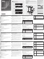
Hardware Review
CE610AL (Local Unit) Front and Rear View
1
LEDs (Power, Link, USB and Video)
2
Firmware Upgrade Port
3
Link Port
4
DVI-D Input Port
5
USB Type B Input
6
Power Jack
CE610AR (Remote Unit) Front and Rear View
1
LEDs (Power, Link, USB and Video)
2
Firmware Upgrade Port
3
Link Port
4
DVI-D Output Port
5
USB Type A Ports
6
Power Jack
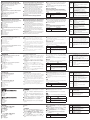
B
Hardware Installation
1
Connect the USB cable (supplied with this package) to the
USB Type B Input on the Local Unit (CE610AL). Plug the
other end of the cable into a USB Type A port on the local
computer.
2
Connect the DVI-D cable (supplied with this package) to the
DVI-D Input port located on the Local Unit (CE610AL). Plug
the other end of the cable into the DVI input port on the
local computer.
3
Plug either end of a Cat 5e cable into the CE610AL's Link
Port. Plug the other end of the Cat 5e cable into the Link
Port of the Remote Unit (CE610AR).
4
Plug the power adapter cable into the power jack on the
CE610AL.
5
Use a DVI cable to connect the DVI-D port on the Remote
Unit (CE610AR) to your monitor.
6
Plug the cables from the remote USB devices (mouse,
keyboard and any device that supports USB 2.0) into a USB
port on the Remote Unit (CE610AR).
7
Plug the second power adapter cable into the power jack
on the CE610AR.
Operation
The CE610A Local and Remote units have front panel LEDs
to indicate their operating status, as shown in the following
tables:
LED Indication
Power
(Green)
• Lights to indicate that the unit is powered on.
Link
(Green)
• Lights to indicate that the connection to the
Local and Remote units is ok.
• OFF when there is a problem with the
connection.
USB
(Green)
• Lights to indicate that the USB connection to the
host computer is working.
• Flashes green to indicate that the host is in
suspend mode.
• OFF indicates that the link is inactive.
Video
(Green)
• Flashes to indicate normal video activity.
• Lights steadily to indicate HDCP video activity.
• OFF indicates that there is no video activity.
B
Package Contents
1 CE610AL DVI HDBaseT KVM Extender with ExtremeUSB
®
(Local Unit)
1 CE610AR DVI HDBaseT KVM Extender with ExtremeUSB
®
(Remote Unit)
1 Custom DVI Cable
1 USB Cable
2 Power Adapters
1 Mounting Kit
1 User Instructions
Hardware Installation
CE610A DVI HDBaseT KVM Extender
www.aten.com
Extension KVM HDBaseT DVI CE610A
www.aten.com
DVI-HDBaseT-KVM-Extender CE610A
www.aten.com
CE610A DVI HDBaseT KVM Extender
www.aten.com
Extensor de KVM HDBase DVI CE610A
www.aten.com
CE610AL Rear View
CE610AR Rear View
Cat 5e cable
DVI
cable
DVI
cable
Local PC
USB cable
7
3
6
2
5
4
1
1
2 3 654
1
2 3 654
CE610AL (Local Unit) Front View
CE610AL (Local Unit) Rear View
CE610AR (Remote Unit) Front View
CE610AR (Remote Unit) Rear View
© Copyright 2016 ATEN
®
International Co., Ltd.
ATEN and the ATEN logo are trademarks of ATEN International Co., Ltd. All rights reserved. All
other trademarks are the property of their respective owners.
This product is RoHS compliant.
Part No. PAPE-1223-961G Printing Date: 11/2016
DVI HDBaseT KVM Extender with ExtremeUSB
®
Quick Start Guide
CE610A
Support and Documentation Notice
All information, documentation, fi rmware,
software utilities, and specifi cations
contained in this package are subject to
change without prior notifi cation by
the manufacturer.
To reduce the environmental impact of our
products, ATEN documentation and software
can be found online at
http://www.aten.com/download/
Technical Support
www.aten.com/support
이 기기는 업무용(A급) 전자파적합기기로서 판매자 또는
사용자는 이 점을 주의하시기 바라며, 가정외의 지역에
서 사용하는 것을 목적으로 합니다.
EMC Information
FEDERAL COMMUNICATIONS COMMISSION INTERFERENCE
STATEMENT:
This equipment has been tested and found to comply with the limits
for a Class A digital device, pursuant to Part 15 of the FCC Rules.
These limits are designed to provide reasonable protection against
harmful interference when the equipment is operated in a commercial
environment. This equipment generates, uses, and can radiate radio
frequency energy and, if not installed and used in accordance with
the instruction manual, may cause harmful interference to radio
communications. Operation of this equipment in a residential area
is likely to cause harmful interference in which case the user will be
required to correct the interference at his own expense.
FCC Caution: Any changes or modifi cations not expressly approved by
the party responsible for compliance could void the user's authority to
operate this equipment.
Warning: This equipment is compliant with Class A of CISPR 32. In a
residential environment this equipment may cause radio interference.
Suggestion: Shielded twisted pair (STP) cables must be used with the
unit to ensure compliance with FCC & CE standards.
This device complies with Part 15 of the FCC Rules. Operation is subject
to the following two conditions:(1) this device mat not cause harmful
interference, and(2) this device must accept any interference received,
including interference that may cause undesired operation.
Scan for
more information
A
Présentation du matériel
CE610AL (Unité locale) Vue de face et de dos
1
LED (Alimentation, Liaison, USB et Vidéo)
2
Port de mise à niveau du fi rmware
3
Port de liaison
4
Port d'entrée DVI-D
5
Entrée USB Type B
6
Fiche d'alimentation
CE610AR (Unité distante) Vue de face et de dos
1
LED (Alimentation, Liaison, USB et Vidéo)
2
Port de mise à niveau du fi rmware
3
Port de liaison
4
Port de sortie DVI-D
5
Ports USB Type A
6
Fiche d'alimentation
B
Installation du matériel
1
Branchez le câble USB (fourni dans l’emballage) sur l’entrée
USB Type B sur l’unité locale (CE610AL). Branchez l'autre
extrémité du câble sur le port USB Type A de l'ordinateur
local.
2
Branchez le câble DVI-D (fourni dans l’emballage) sur le port
d'entrée DVI-D situé sur l'unité locale (CE610AL). Branchez
l'autre extrémité du câble sur le port d’entrée DVI de
l'ordinateur local.
3
Branchez l'une des extrémités d'un câble Cat 5e sur le port
de liaison du CE610AL. Branchez l'autre extrémité du câble
Cat 5e sur le port de liaison de l'unité distante (CE610AR).
4
Branchez le câble de l'adaptateur secteur dans la prise
d'alimentation du CE610AL.
5
Utilisez un câble DVI pour raccorder le port de sortie DVI-D
de l’unité distante (CE610AR) à votre moniteur.
6
Branchez les câbles des périphériques USB distants (souris,
clavier et tout appareil périphérique USB 2.0) dans un port
USB de l'unité distante (CE610AR).
7
Branchez le câble du second adaptateur secteur dans la
prise d'alimentation du CE610AR.
Fonctionnement
Les unités locale et distante CE610A ont des LED sur le
panneau avant pour indiquer leur état de fonctionnement,
comme le montrent les tableaux suivants :
LED Indication
Alimentation
(Verte)
• S’illumine pour indiquer que l’unité est sous
tension.
Liaison
(Verte)
• S'illumine pour indiquer que la connexion
vers les unités locale et distante est correcte.
• OFF (éteint) quand il y a un problème avec la
connexion.
USB (Verte)
• S’illumine pour indiquer que la connexion
USB vers l'ordinateur hôte fonctionne.
• Clignote en vert pour indiquer que l'hôte est
en mode veille.
• OFF (éteint) indique que le lien est inactif.
Vidéo (Verte)
• Clignote pour indiquer une activité vidéo
normale.
• S’illumine en permanence pour indiquer
l'activité vidéo HDCP.
• OFF (éteint) indique qu'il n'y a pas d'activité
vidéo.
A
Hardwareübersicht
CE610AL (lokales Gerät) – Ansicht von vorne und
hinten
1
LEDs (Betrieb, Verbindung, USB und Video)
2
Firmware-Aktualisierungsport
3
Verbindungsport
4
DVI-D-Eingang
5
USB-Typ-B-Eingang
6
Netzanschluss
CE610AR (externes Gerät) – Ansicht von vorne und
hinten
1
LEDs (Betrieb, Verbindung, USB und Video)
2
Firmware-Aktualisierungsport
3
Verbindungsport
4
DVI-D-Ausgang
5
USB-Typ-A-Ports
6
Netzanschluss
B
Hardwareinstallation
1
Verbinden Sie das USB-Kabel (im Lieferumfang enthalten)
mit dem USB-Typ-B-Eingang am lokalen Gerät (CE610AL).
Verbinden Sie das andere Kabelende mit einem USB-Typ-A-
Port am lokalen Computer.
2
Verbinden Sie das DVI-D-Kabel (im Lieferumfang enthalten)
mit dem DVI-D-Eingang am lokalen Gerät (CE610AL).
Verbinden Sie das andere Kabelende mit dem DVI-Eingang
am lokalen Computer.
3
Schließen Sie eines der Enden eines Cat-5e-Kabels an den
Verbindungsport des CE610AL an. Verbinden Sie das andere
Ende des Cat-5e-Kabels mit dem Verbindungsport am
externen Gerät (CE610AR).
4
Schließen Sie das Netzteilkabel an den Netzanschluss am
CE610AL an.
5
Verbinden Sie den DVI-D-Anschluss am externen Gerät
(CE610AR) über ein DVI-Kabel mit Ihrem Monitor.
6
Schließen Sie die Kabel von den externen USB-
Geräten (Maus, Tastatur und andere Geräte, die USB
2.0 unterstützen) an den USB-Port am externen Gerät
(CE610AR) an.
7
Schließen Sie das zweite Netzteilkabel an den Netzanschluss
am CE610AR an.
Bedienung
Die lokalen und externen Geräte CE610A besitzen LEDs an der
Frontblende, die, wie in den folgenden Tabellen dargestellt,
ihren Betriebsstatus anzeigen:
LED Anzeige
Betrieb
(grün)
• Zeigt durch Leuchten an, dass das Gerät
eingeschaltet ist.
Verbindung
(grün)
• Zeigt durch Leuchten an, dass die Verbindung
mit den lokalen und externen Geräten
funktioniert.
• Aus, wenn ein Problem mit der Verbindung
vorliegt.
USB (grün)
• Zeigt durch Leuchten an, dass die USB-
Verbindung zum Hostcomputer funktioniert.
• Zeigt durch grünes Blinken an, dass sich der
Host im Ruhezustand befi ndet.
• Bei erlischter Anzeige ist die Verbindung
inaktiv.
Video
(grün)
• Zeigt durch Blinken normale Videoaktivität an.
• Zeigt durch Leuchten HDCP-Videoaktivität an.
• Aus, falls keine Videoaktivität erfolgt.
A
Presentación del hardware
Vista frontal y trasera del CE610AL (Unidad local)
1
LEDs (Alimentación, Enlace, USB y Vídeo)
2
Puerto de actualización del fi rmware
3
Puerto de enlace
4
Puerto de entrada de DVI-D
5
Entrada USB Tipo B
6
Conector de alimentación
Vista frontal y trasera del CE610AR (Unidad remota)
1
LEDs (Alimentación, Enlace, USB y Vídeo)
2
Puerto de actualización del fi rmware
3
Puerto de enlace
4
Puerto de salida de DVI-D
5
Puertos USB Tipo A
6
Conector de alimentación
B
Instalación del hardware
1
Conecte el cable USB (incluido en este paquete) en el puerto
USB de tipo B de la unidad local (CE610AL). Enchufe el otro
extremo del cable a un puerto USB de tipo A en el equipo
local.
2
Conecte el cable DVI-D (incluido en este paquete) al puerto
de entrada DVI-D de la unidad local (CE610AL). Enchufe el
otro extremo del cable en el puerto DVI en el equipo local.
3
Enchufe uno de los extremos del cable Cat 5e en el puerto
de enlace del CE610AL. Enchufe el otro extremo del
cable Cat 5e en el puerto de enlace de la unidad remota
(CE610AR).
4
Enchufe el cable del adaptador de alimentación en la toma
del CE610AL.
5
Utilice un cable DVI para conectar el puerto DVI-D de la
unidad remota (CE610AR) a su monitor.
6
Enchufe los cables de los dispositivos USB remotos (ratón,
teclado y cualquier dispositivo que admite USB 2.0) en un
puerto USB de la unidad remota (CE610AR).
7
Enchufe el segundo cable del adaptador de alimentación en
la toma del CE610AR.
Funcionamiento
Las unidades CE610A local y remota tienen LEDs en el panel
frontal para indicar el estado de funcionamiento, tal como se
muestra en las siguientes tablas:
LED Indicación
Alimentación
(Verde)
• Se ilumina para indicar que la unidad está
encendida.
Enlace
(Verde)
• Se ilumina para indicar que la conexión
al transmisor y las unidades remotas es
correcta.
• Se muestra APAGADO cuando hay un
problema con la conexión.
USB (Verde)
• Se ilumina para indicar que la conexión USB
al equipo host está funcionando.
• Parpadea en verde para indicar que el host
está en modo de suspensión.
• APAGADO indica que el enlace está inactivo.
Vídeo
(Verde)
• Parpadea para indicar actividad de vídeo
normal.
• Se ilumina para indicar actividad de vídeo
HDCP.
• APAGADO indica que no hay ninguna
actividad de vídeo.
A
Descrizione hardware
CE610AL (unità locale) veduta frontale e posteriore
1
LED (alimentazione, Link, USB e video)
2
Porta di aggiornamento fi rmware
3
Porta Link
4
Porta di ingresso DVI-D
5
Input USB tipo B
6
Connettore d'alimentazione
CE610AR (unità remota) veduta frontale e
posteriore
1
LED (alimentazione, Link, USB e video)
2
Porta di aggiornamento fi rmware
3
Porta Link
4
Porta output DVI-D
5
Porte USB di tipo A
6
Connettore d'alimentazione
B
Installazione dell'hardware
1
Collegare il cavo USB (fornito in dotazione) alla porta USB di
tipo B dell’unità locale (CE610AL). Collegare l'altra estremità
del cavo a una porta USB di tipo A del computer locale.
2
Collegare il cavo DVI (fornito in dotazione) alla porta Input
DVI-D dell’unità locale (CE610AL). Collegare l'altra estremità
del cavo alla porta input DVI del computer locale.
3
Collegare una delle estremità di un cavo Cat 5e alla porta
Link di CE610AL. Collegare l'altra estremità del cavo Cat 5e
alla porta Link dell'unità remota (CE610AR).
4
Collegare il cavo dell’adattatore di corrente al connettore
d’alimentazione di CE610AL.
5
Utilizzare un cavo DVI per collegare la porta DVI-D dell’unità
remota (CE610AR) al monitor.
6
Collegare i cavi dai dispositivi USB remoti (mouse, tastiera
e qualsiasi dispositivo che supporta USB 2.0) ad una porta
USB dell’unità remota (CE610AR).
7
Collegare il cavo del secondo ’adattatore di corrente al
connettore d’alimentazione di CE610AR.
Funzionamento
Le unità locali e remote di CE610A sono dotate di LED su
pannello frontale per indicare il loro stato di funzionamento,
come indicato nelle tabelle che seguono:
LED Indicazioni
Alimentazione
(verde)
• Si accende per indicare che l'unità è
accesa.
Link (verde)
• Si accende per indicare che la connessione
tra le unità locale e remota è OK.
• SPENTO quando c'è un problema con la
connessione.
USB (verde)
• Si accende per indicare che la connessione
USB al computer host è in funzione.
• Lampeggia di colore verde per indicare che
l'host è in modalità di sospensione.
• SPENTO signifi ca che il collegamento non è
attivo.
Video (verde)
• Lampeggia per indicare la normale attività
video.
• Resta acceso per indicare l'attività video
HDCP.
• SPENTO indica l’assenza di attività video.
A
Hardware Review
La pagina si sta caricando...
-
 1
1
-
 2
2


ATEN DVI HDBaseT KVM Extender Guida Rapida
- Categoria
- Estensori della console
- Tipo
- Guida Rapida
- Questo manuale è adatto anche per
in altre lingue
- English: ATEN DVI HDBaseT KVM Extender Quick start guide
- français: ATEN DVI HDBaseT KVM Extender Guide de démarrage rapide
- español: ATEN DVI HDBaseT KVM Extender Guía de inicio rápido
- Deutsch: ATEN DVI HDBaseT KVM Extender Schnellstartanleitung
- русский: ATEN DVI HDBaseT KVM Extender Инструкция по началу работы
- português: ATEN DVI HDBaseT KVM Extender Guia rápido
- 日本語: ATEN DVI HDBaseT KVM Extender クイックスタートガイド