Candy MIC25GDFX Manuale utente
- Categoria
- Microonde
- Tipo
- Manuale utente
Questo manuale è adatto anche per

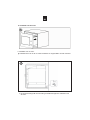
Installation Instruction
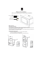
Please Read the Manual Carefully Before Installation
Please Note
Electrical connection
The oven is fitted with a plug and must be only connected to a properly installed earthed
socket. In accordance with the appropriate regulations, the socket must only be installed and
the connecting cable must only be replaced by a qualified electrician.
If the plug is no longer accessible following installation and all-pole isolating switch must
be present on the installation side with a contact gap at least 3mm.
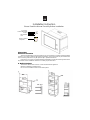
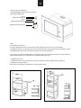
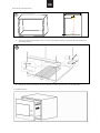
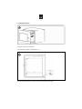
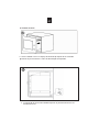
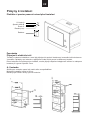
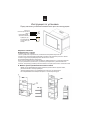
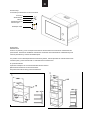
A. Built-in furniture
The built-in cabinet shall not have a rear wall behind the appliance.
Minimum installation height is 85cm.
Do not cover ventilation slots and air intake points.
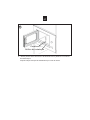
Bottom Bracket B
2*Screw A
Scre
w C
Trim-Kit Plastic
cover
FRONT
420
297
357
3
36
10
BOTTON CABINET TEMPLATE
Botton Cabinet
Template
GB

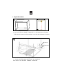
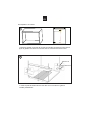
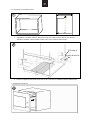
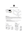
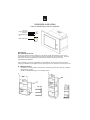
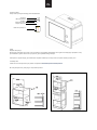
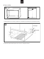
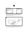
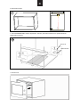
B. Prepare the Cabinet.
2
1
FRONT
420
297
357
3
36
10
BOTTON CABINET TEMPLATE
1.
the BOTTOM CABINET TEMPLATE
Put
on the bottom plane of cabinet
.
2.
BRACKET
B
two
with
And make the center line of the template coincides with the bottom of cabinet.
Fix
the BOTTOM
And r
emove the BOTTOM CABINET TEMPLATE
SCREW A.
.
2*Screw A
Bottom Bracket B
GB

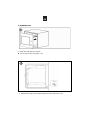
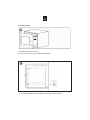
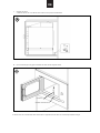
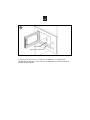
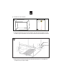
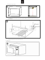
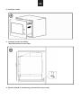
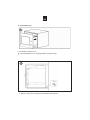
3.
Bottom Bracket B is just installed against the back shell of the oven.
z Do not trap or kink the power cord.
4
. Install the oven.
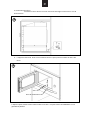
C.
4
3
.
Install the oven into the cabinet.
GB

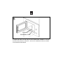
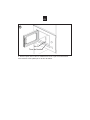
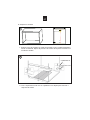
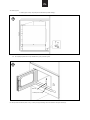
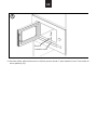
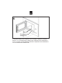
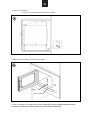
INSTALLATION HOLE of TRIM KIT.
5
to the INSTALLATION HOLE.
Then fix the TRIM-KIT PLASTIC COVER
Screw C
Installation Hole
5
. Open the door; fix the oven to the cabinet with SCREW C at the
GB

Manuel d'installation
Merci de lire attentivement le manuel avant l'installation
Merci de noter
Connection électrique
Le four est équipé d'une prise et doit être connecté à une prise terre adaptée.
Conformément à la réglementation, la prise doit être installée et le cable de connection doit
être remplacé seulement par un électricien qualifié.
Si le prise n'est pas accessible après l'installation le commutateur doit être accessible sur le
côté de l'installation avec un espace de 3mm.
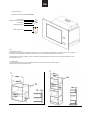
A.Meuble d'encastrement
Il n'est pas recommandé d'avoir une cloison derrière l'appareil.
La hauteur d'installation minimale est 85cm.
Ne couvrez pas les fentes de ventilation et les zones de prise d'air.
Patte de fixation B
2 vis A
Vis C
Cache plastique
FRONT
420
297
357
3
36
10
BOTTON CABINET TEMPLATE
Gabarit pour le
bas du meuble
FR

B Préparation du meuble
2
1
FRONT
420
297
357
3
36
10
BOTTON CABINET TEMPLATE
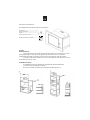
1 .Mettre le gabarit sur le bas de la niche du meuble en faisant en sorte que la
ligne du gabarit soit centrer et coincide avec le centre du bas de la niche.
2. Fixer la patte de fixation B avec les deux vis A et enlever le gabarit
installé précédement.
2*Screw A
Bottom Bracket B
FR

3. Installer le four dans la niche.
Ne pas coincer ou plier le câble d'alimentation.
4
C. Installer le four
4. La patte de fixation B est installée contre la paroi arrière du four
3
FR

5
Vis C
Trou de fixation
5. Ouvrir la porte, fixer le four au meuble avec la Vis C par le trou de fixation.
Puis mettre le cache plastique sur le trou de fixation.
FR

FRONT
420
297
357
3
36
10
BOTTON CABINET TEMPLATE
Istruzioniperl'installazione
Sipregadileggereattentamenteilmanuale
primadell’installazione
2vitiA
SupportoinferioreB
ViteC
Kitguarnizioniplastiche
Modelloinferiorenicchia
Nota
Ilcollegamentoelettrico
Ilfornoèdotatodiunaspinaedeveesseresolocollegatoadunapresaconunacorretta
installazionedi
terra.Inconformitàconlenormativedelcaso,lapresadeveessereinstallataeilcavo
dicollegamentodeveesseresostituitosolodaunelettricistaqualificato.
Selaspinanonèpiùaccessibiledopol'installazionetuttiipolisezionatoridevonoesserepresentisul
latodiinstallazioneconunadistanzatrai
contattidialmeno3mm.
AͲMobiledaincasso
Ilmobiledaincassonondeveavereunapareteposterioredietrol'apparecchio.L’altezzadi
installazioneminimaè85cm.
Noncoprirelefessurediventilazioneeipuntidipresad'aria.
IT

B–Prepararelanicchiadiincasso
1. Appoggiareilmodelloinferioredellanicchianelpianodellainternodellanicchiastessae
allineare
il
modello
inferiore
della
nicchia
con
il
piano
inferiore
della
nicchia.
2. FissareilsupportoinferioreBconleduevitiA
erimuovere
ilmodelloinferioredellanicchia.
C.Installazionedelforno.
IT
1
FRONT
420
297
357
3
36
10
BOTTON CABINET TEMPLATE
2
2*Screw A
Bottom Bracket B
3

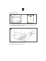
4. IlsupportoinferioreBdeveessereinstallatocontrolaparteposterioredellastrutturadel
forno.
5. Aprire la porta; fissare il forno nella nicchia con la vite C e coprire il buco di installazione con la
guarnizione plastica.
3.Installazionedelforno.
•Installareilfornodentrolanicchia.Evitarediattorcigliareobloccareilcavodi
alimentazione.
IT
4
5
ViteC
Bucodiinstallazionevite

FRONT
420
297
357
3
36
10
BOTTON CABINET TEMPLATE
Installationsanleitung
Bitte lesen Sie das Handbuch Vor der Installation
2 SchraubenA
Niederösterreich unterstützt
B
Schraube
C
Plastic Dichtungssatz
Model weniger Nische
Note
Der elektrische Anschluss
Der Backofen ist mit einem Stecker ausgerüstet und darf nur an eine ordnungsgemäß installierte Boden. In Übereinstimmung mit den geltenden
Vorschriften muss die Steckdose installiert und das Kabel darf nur von einem qualifizierten Elektriker ersetzt werden.
Wenn der Stecker nicht mehr zugänglich ist nach der Installation alle Stangen geschnitten vorhanden sein muss auf die Installation mit einem
Kontaktabstand von 3 mm.
A - Möbelkollektion
Der Schrank muss nicht über eine vertiefte Rückwand hinter dem Gerät. Die minimale Aufbauhöhe ist 85cm.
Nicht die Lüftungsgitter und Lufteinlass Punkte.
DE

1. Setzen Sie den Boden der Nische Modell in Form von internen Nische selbst und richten Sie die Unterseite der Nische Modell mit der
unteren Etage der Nische.
2. Befestigen Sie die untere Halterung B mit den beiden Schrauben A und entfernen Sie den unteren Teil der Nische Modell.
C.
Installieren des Ofens
DE
B - Bereiten Sie die Nische Sammlung
1
FRONT
420
297
357
3
36
10
BOTTON CABINET TEMPLATE
2

5.
Öffnen Sie die Tür in den Backofen Nische mit Schraube C eingestellt und decken das Loch mit dem Setup-Kunststoff versiegelt.
DE
3. Installieren des Ofens.
• Installieren Sie den Ofen in der Nische. Nicht verdrehen oder sperren Sie das Netzkabel.
4. Die untere Halterung B muss gegen die Rückseite des Ofens Struktur eingebaut werden.
4
5
Schraube C
Installation Schraubenloch

FRONT
420
297
357
3
36
10
BOTTON CABINET TEMPLATE
InstruccionesdeInstalación
LeerdetenidamenteelManualantesdelaInstalación
2*TornillosA‐‐‐‐‐‐‐‐‐‐‐‐‐‐‐‐‐‐‐‐‐‐‐‐‐‐‐‐‐‐‐‐‐‐‐‐‐‐‐‐
SoportedelfondoB‐‐‐‐‐‐‐‐‐‐‐‐‐‐‐‐‐‐‐‐‐‐‐‐‐‐‐‐‐‐‐‐
TornilloC‐‐‐‐‐‐‐‐‐‐‐‐‐‐‐‐‐‐‐‐‐‐‐‐‐‐‐‐‐‐‐‐‐‐‐‐‐‐‐‐‐‐‐‐‐‐
CubiertaeplásticoTrim‐kit‐‐‐‐‐‐‐‐‐‐‐‐‐‐‐‐‐‐‐‐‐‐
Plantilladelfondodelacavidad‐‐‐‐‐‐‐‐‐‐‐‐‐‐‐
Atención
ConexiónEléctrica
Elhonrodisponedeunaclavijaquesólopuedeconectarseaunenchufeconlatoma
detierraadecuada.Deacuerdoconlasregulacionespertinentes,sólounelectricista
cualificadopodráinstalarelenchufey,sifuesenecesario,cambiarelcabledeconexión.
Sinohayenchufehade
instalarseunoconuninterruptordevariasclavijasyunhueco
decontactodealmenos3mm.
A.Muebleencastrado
Lacavidaddeencastrenopuedetenerpareddelantedelelectrodoméstico.
Laalturamínimadeinstalaciónes85cm.
Nocubrirlassalidasdeventilaciónnilospuntosde
absorcióndeaire.
ES

B.Preparacióndelacavidad
1.PonerlaPLANTILLADELFONDODELACAVIDADenelfondodelacavidad.Hacercoincidirla
líneacentraldelaplantillaconelfondodelacavidad.
2.FijarelSOPORTEDELFONDOBcondosTORNILLOSA.
RetirarlaPLANTILLADELFONDODELACAVIDAD.
ES
1
FRONT
420
297
357
3
36
10
BOTTON CABINET TEMPLATE
2
2*Screw A
Bottom Bracket B

4
3
C.Instalacióndelhorno
3.Instalarelhornoenlacavidad.
*Nomachacarnidoblarelcableeléctrico.
4.ElSoportedelFondoBsecolocacon tralarejillaposteriordelhorno.
ES

5.Abrirlapuerta,fijarelhornoalacavidadconelTORNILLOCenelAGUJERODE
INSTALACIÓNdelTRIM‐KIT.AcontinuaciónfijarlaCOBERTURADEPLÁSTICOTRIM‐KITal
AGUJERODEINSTALACIÓN.
TornilloC
AgujerodeInstalación
ES
5

Instruções de instalação
Atenção
Ligação eléctrica
O forno está equipado com uma ficha que só deve ser ligada a uma tomada com terra
correctamente instalada. A ligação eléctrica só deve ser feita por um electricista qualificado.
Se a ficha deixar de estar acessível após a instalação do forno e todos os pólos de
isolamento de mudança devem estar presentes ao lado de instalação com uma abertura de
contacto de, pelo menos, 3 milímetros.
A. Encastrar em móveis
O armário onde o forno vai ser encastrado não deve ter parede traseira por trás do
aparelho, deve ter o fundo aberto.
A altura mínima de instalação é 85 centímetros.
Não cubra as aberturas de ventilação e os pontos de entrada de ar.
Suporte B do fundo
2 Parafusos A
Parafuso C
Tampa de plástico para
cobertura/acabamento
FRONT
420
297
357
3
36
10
BOTTON CABINET TEMPLATE
Aro de encastre no
fundo do armário.
PT

B. Preparar o encastre
2
1
FRONT
420
297
357
3
36
10
BOTTON CABINET TEMPLATE
1 - Coloque o aro de encastre no fundo do armário em que o electrodoméstico
vai ser encastrado. Depois faça a linha de centro do esquema coincidir com
o fundo do armário.
2 - Fixe o suporte do fundo com os 2 parafusos A e depois pode remover o
esquema do fundo.
2 parafusos A
Suporte B do fundo
PT
La pagina si sta caricando...
La pagina si sta caricando...
La pagina si sta caricando...
La pagina si sta caricando...
La pagina si sta caricando...
La pagina si sta caricando...
La pagina si sta caricando...
La pagina si sta caricando...
La pagina si sta caricando...
La pagina si sta caricando...
La pagina si sta caricando...
La pagina si sta caricando...
La pagina si sta caricando...
La pagina si sta caricando...
La pagina si sta caricando...
La pagina si sta caricando...
La pagina si sta caricando...
La pagina si sta caricando...
La pagina si sta caricando...
La pagina si sta caricando...
-
 1
1
-
 2
2
-
 3
3
-
 4
4
-
 5
5
-
 6
6
-
 7
7
-
 8
8
-
 9
9
-
 10
10
-
 11
11
-
 12
12
-
 13
13
-
 14
14
-
 15
15
-
 16
16
-
 17
17
-
 18
18
-
 19
19
-
 20
20
-
 21
21
-
 22
22
-
 23
23
-
 24
24
-
 25
25
-
 26
26
-
 27
27
-
 28
28
-
 29
29
-
 30
30
-
 31
31
-
 32
32
-
 33
33
-
 34
34
-
 35
35
-
 36
36
-
 37
37
-
 38
38
-
 39
39
-
 40
40


Candy MIC25GDFX Manuale utente
- Categoria
- Microonde
- Tipo
- Manuale utente
- Questo manuale è adatto anche per
Documenti correlati
Altri documenti
-
Hoover HMGV28GDFB Manuale utente
-
Hoover HMG200X Manuale utente
-
-
Whirlpool MWI 222.1 X Manuale del proprietario
-
Whirlpool MWK 221.1 X /HA Manuale del proprietario
-
HOTPOINT/ARISTON MWK 222.1 X/HA Guida utente
-
Whirlpool AMW 1601/IX Guida utente
-
-
-
HOTPOINT/ARISTON MWHA 222.1 Manuale del proprietario