
LIBRETTO D’ USO E MANUTENZIONE
PIANI DI COTTURA DA INCASSO
DOMINO
HVG31
HVG32
LIB30297
HOOVER -Via Privata Eden Fumagalli - 20047 Brugherio ( Milano) - Italy

ISTRUZIONI PER IL MONTAGGIO
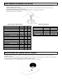
DATI TECNICI
HVG32 HVG31
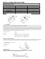
1. Montaggio
L’installazione è a carico dell’acquirente.La Casa Costruttrice è esonerata da questo servizio.Gli eventuali interventi richiesti alla
Casa Costruttrice, se dipendono da un’errata installazione, non sono compresi nella garanzia.
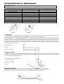
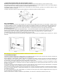
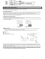
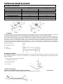
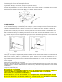
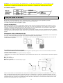
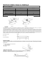
I piani da incasso sono predisposti per l’installazione in top realizzati in qualsiasi materiale, purché resistente ad una
temperatura di 100° C, e di spessore variabile fra 25 e 40 mm.Qualora il piano venga incassato in modo che sul suo lato sinistro
o destro ci sia la parete di un mobile, la distanza fra la parete verticale ed il bordo del piano, deve essere almeno 150 mm;
mentre la distanza fra la parete posteriore ed il bordo del piano deve essere almeno di 55mm. Tra il piano da incasso ed il vano
sottostante deve essere inserita una parete di divisione in materiale isolante (legno o similari).Tale parete deve distare almeno
10 mm dal fondo della cassetta.
X =minimo 150 mm
Z = 10mm
Y = parete divisoria
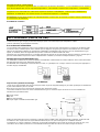
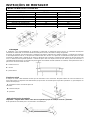
Fissaggio al mobile
Il fissaggio al mobile è ottenuto mediante staffe di fissaggio che vengono fornite come accessori.Nella parte inferiore della
cassetta sono già predisposti i fori dove vengono inserite le piastrine autofilettanti (A) cui devono essere avvitate le apposite viti
(C) che bloccano le staffe di fissaggio (B).
A = piastrine da inserire sul fondo del
piano ad incasso
B = staffa di fissaggio
C = vite
Applicazione sigillante
Importante-La figura qui sotto indica come deve essere applicato il sigillante su tutto il perimetro.
Quest’apparecchio è stato concepito per uso di tipo non professionale all’interno d’abitazioni.
2
MODELLI HVG31 HVG32
Tensione/Frequenza 230V/50Hz 230V/50Hz
Bruciatore semirapido 1
Bruciatore rapido 1
Bruciatore tripla corona 1
Accensione automatica si si
Dispositivo di sicurezza gas si si
Dimensione prodotto (l x p) mm 288x510 288x510
Dimensione dell’incasso (l x p) mm 275x490 275x490

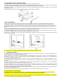
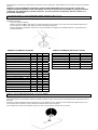
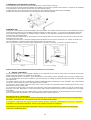
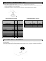
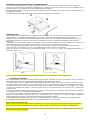
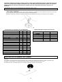
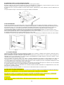
Accoppiamento di due o più pianeti domino
Eseguire un taglio sul piano di lavoro che permetta l’incasso di due o più piani domino.
Per primo posizionare il supporto in acciaio (E) fornito in dotazione nell’imballo e successivamente inserire il piano di cottura (G)
come indicato nella figura sottostante.Nello spazio rimasto libero inserire il piano di cottura (F).
3
Il supporto in acciaio, con la guarnizione presente sui due piani domino garantirà una chiusura ermetica contro l’eventuale
infiltrazione di liquidi.
Il fissaggio dei domino al top è ottenuto mediante l’utilizzo del kit di staffe in dotazione.
F
G
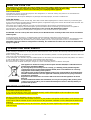
Locale d’installazione
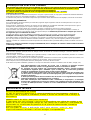
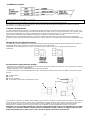
L’utilizzo di un apparecchio di cottura a gas produce calore e umidità nel locale in cui è installato.Vogliate assicurare una
buon’areazione del locale mantenendo aperti gli orefizi di ventilazione naturale o installando una cappa d’aspirazione con
condotto di scarico(Fig. 1-2).Un utilizzo intensivo e prolungato dell’apparecchio può necessitare di un’areazione supplementare
per esempio l’apertura di una finestra o un’areazione più efficace aumentando la potenza d’aspirazione meccanica se essa
esiste.
In caso non sia possibile installare la cappa (Fig.2) è necessario l’impiego di un elettroventilatore applicato alla parete esterna o
alla finestra dell’ambiente purché esistano nel locale le aperture per l’entrata dell’aria.
Quest’elettroventilatore deve avere una portata tale da garantire,per un ambiente cucina, un ricambio orario d’aria di 3-5 volte il
suo volume. L’installatore deve attenersi alle norme in vigore UNI-CIG 7129 e 7131.
Fig. 1
Nel caso in cui l’ apparecchio fosse sprovvisto di termocoppia (dispositivo di sicurezza) la presa di ventilazione (fig.1) dovrà
essere di 200cm² minimo.
Fig. 2
Tra il piano ed una eventuale cappa aspirante deve esserci una distanza di almeno 70cm.
2. Collegamento elettrico
Controllare i dati riportati sulla targhetta posta sul fondo del piano di cottura, quindi accertarsi che tensione nominale di rete e
potenza disponibili, siano adatte al suo funzionamento.
Prima di effettuare il collegamento verificare l’efficienza dell’impianto di messa a terra.La messa a terra dell’apparecchio è
obbligatoria per Legge. La Casa Costruttrice declina ogni responsabilità per eventuali danni a persone o a cose derivanti dalla
mancata osservanza di questa norma.
Per eventuali modelli sprovvisti di spina, montare sul cavo una spina normalizzata che sia in grado di sopportare il carico
indicato in targhetta.Il conduttore di terra del cavo è contraddistinto dai colori giallo verde.In ogni caso la spina deve essere
accessibile.
Nel caso si desideri realizzare una connessione fissa alla rete, si dovrà interporre, tra l’apparecchio e la rete un dispositivo
omnipolare d’interruzione con distanza dei contatti di almeno 3 mm.
Per il collegamento del cavo con il piano di cottura è necessario allentare e rimuovere il coperchio della morsettiera sino ad
arrivare ai contatti nel suo interno. Effettuato il collegamento, il cavo deve essere bloccato con il sistema di fissaggio in
dotazione e il coperchio della morsettiera immediatamente richiuso.
In caso di sostituzione del cavo di alimentazione, il conduttore di terra (giallo-verde), deve obbligatoriamente essere più lungo di
10mm rispetto ai conduttori di linea.
Utilizzare esclusivamente un cavo in gomma tipo H05RR-F, la sezione dei cavetti deve essere di 3x1.5 mm.
DICHIARAZIONE DI CONFORMITA'
Questo apparecchio, nelle parti destinate a venire a contatto con sostanze alimentari, è conforme alla prescrizione della Dir.
CEE 89/109 e al D.L. di attuazione N° 108 del 25/01/92; sostituita dal Regolamento 1935/2004/EC.
Apparecchio conforme alle direttive Europee 73/23/CEE e 89/336/CEE, sostituite rispettivamente da 2006/95/CE e 204/108/CE,
e successive modifiche nonché alla direttiva Europea 90/396/CE.

ATTENZIONE:nel caso si renda necessario sostituire il cavo di alimentazione, assicurarsi di rispettare il seguente
codice-colore durante il collegamento dei singoli fili:
ALLACCIAMENTO (PARTE A GAS)
Sul piano a gas è indicato, con apposite targhette, il tipo di gas per il quale l’apparecchio è predisposto.
E tuttavia possibile usare altri tipi di gas dopo aver eseguito dei semplici adattamenti.
(Vedere indicazioni paragrafi seguenti.)
Collegamento all’alimentazione
Il collegamento dell’apparecchio alla tubazione o alla bombola del gas dovrà essere effettuato come prescritto dalle Norme UNI-
CIG7129 e 7131, solo dopo essersi accertati che esso è regolato per il tipo di gas con cui sarà alimentato.In caso contrario
eseguire le operazioni indicate al paragrafo <<Adattamento ai diversi tipi di gas>>.Nel caso di alimentazione con gas liquido, da
bombola, utilizzare regolatori di pressione conformi alle Norme UNI-CIG 7432.
Importante: per un sicuro funzionamento, per un adeguato uso dell’energia e maggiore durata dell’apparecchio, assicurarsi che
la pressione di alimentazione rispetti i valori indicati nella tabella (“Dati tecnici bruciatori” pag.6)
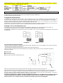
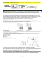
Montaggio del raccordo alimentazione gas
Le istruzioni sono rivolte al personale autorizzato all’installazione dell’apparecchio in conformità alle norme UNI-CIG-
7131.Qualsiasi intervento deve essere eseguito con l’apparecchiatura disinserita elettricamente.
ATTENZIONE: nell’imballo sono presenti due raccordi, uno cilindrico e uno conico, scegliere quello appropriato in base al paese
d’installazione.
CILINDRICO CONICO
Sequenza delle operazioni di montaggio:
-Avvitare il raccordo orientabile nel tubo rampa di entrata del gas dell’apparecchio A1 (che è filettato ½ gas maschio cilindrico)
inserendo l’apposita guarnizione di tenuta A2.
Serrare forte il raccordo tenendo presente di orientarlo nella direzione desiderata.
-Allacciare il piano di cottura alla rete di alimentazione gas avvitando il tubo di rete al raccordo orientabile inserendo la
guarnizione di tenuta.
4
A1=Tubo rampa
A2=Guarnizione
A3=Raccordo orientabile
A4=Tubo rigido o flessibile d’alimentazione gas
A1
A2
A4
A3
Utilizzare esclusivamente tubi conformi alla Norma UNI-CIG 9891 e guarnizioni di tenuta conformi alla
UNI-CIG 9264.La messa in opera di tali tubi deve essere effettuata in modo che la loro lunghezza, in condizioni di massima
estensione, non sia maggiore di 2000 mm.Per agevolare l’installazione e per evitare rischi di perdite gas, si consiglia di
allacciare prima il raccordo orientabile nel piano di cottura e successivamente sul tubo delle rete di alimentazione. L’inversione
di questa sequenza potrebbe creare problemi di tenuta gas tra tubo e piano.
Importante: ad installazione ultimata controllare la perfetta tenuta di tutti i raccordi utilizzando una soluzione saponosa
e mai una fiamma.Assicurarsi inoltre, che il tubo flessibile non possa essere a contatto con una parte mobile del
modulo da incasso (es. cassetto) e che non sia situato in luoghi dove possa essere danneggiato.

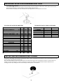
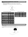
ADATTAMENTO AI DIVERSI TIPI DI GAS
Per adattare il piano ad un tipo di gas diverso da quello per il qual è previsto, eseguire nell’ordine le seguenti operazioni:
-asportare la griglia e il bruciatore
-svitare gli iniettori ( M ) con un’apposita chiave a tubo e sostituirli con quelli di diametro adatto al nuovo tipo di gas
utilizzato (vedere tabella “Dati tecnici bruciatori”).
5
-ad operazione ultimata sostituire la vecchia etichetta di taratura con quella data in dotazione
corrispondente alla nuova installazione
.
Modello HVG31 HVG32
Potenza Totale KW 3.8 4.75
Consumo
G30 g/h 277 346
G20 m³/h 0.362 0.453
G25 m³/h 0.421 0.526
G110 m³/h 0.862 1.078
G120 m³/h 0.770 0.962
Bruciatori SR R TC
Portata termica nominale kw 1.75 3.00 3.8
Portata termica ridotta kw 0.70 1.00 1.75
Portata termica ridotta DE-AT kw 0.90 1.30
Ø INIETTORE:
G30/G31 28..30/30-37mbar mm 0.65 0.85 0.98
G30/G31 50mbar mm 0.58 0.75 0.77
G20 20mbar mm 0.97 1.15 1.35
G25 25mbar mm 0.94 1.21 1.45
G25 20mbar mm 1.00 1.34 1.52
G110 8mbar mm 1.85 2.60 3.20
G120 8mbar mm 1.80 2.40 3.00
Ø BY-PASS:
G30/G31 28..30/30-37mbar mm 0.31 0.42 0.60
G30/G31 50mbar mm 0.31 0.42 0.60
G20 20mbar mm Reg. Reg. Reg.
G25 25mbar mm Reg. Reg. Reg.
G25 20mbar mm Reg. Reg. Reg.
G110 8mbar mm Reg. Reg. Reg.
G120 8mbar mm Reg. Reg. Reg.
DATI TECNICI BRUCIATORI DATI TECNICI PIANI
M
REGOLAZIONE DEL MINIMO DELLA FIAMMA
Accendere i bruciatori portando il rubinetto in posizione di minimo e sfilare la manopola (estraibile perché semplicemente
montata a pressione).
Quindi con un piccolo cacciavite agire sulla vite di regolazione del rubinetto in senso antiorario per aumentare la portata del gas,
in senso orario per diminuirla, fino ad ottenere una fiamma lunga 3 o 4mm.
Per l’impiego di gas GPL (in bombola) avvitare in senso orario fino a fine corsa il by-pass.

USO DEL PIANO DI COTTURA
Questo apparecchio non è destinato ad essere usato da bambini e persone incapaci o inesperte all'uso del prodotto, a
meno che non vengano sorvegliate o istruite riguardo all'uso dell'apparecchio da una persona responsabile della loro
sicurezza.
Sorvegliare i bambini in modo tale da assicurarsi che non giochino con l'apparecchio.
Istruzioni per l’utente
Quest’apparecchio dovrà essere destinato solo all’uso al qual è stato concepito, e cioè per la cottura ad uso domestico.Ogni
altro uso è da considerarsi improprio e quindi pericoloso.
Il costruttore non può essere considerato responsabile per eventuali danni derivanti da usi impropri, erronei ed irragionevoli.
Uso dei bruciatori
Se i bruciatori non sono usati per diversi giorni attendere qualche secondo prima dell’accensione per dar modo all’aria presente
nella tubazione di uscire.
Per accendere i bruciatori del piano di cottura, essendo dotati di accensione automatica è sufficiente premere e ruotare la
manopola fino alla piccola stella.Il generatore di accensione è di tipo a scarica ripetitiva.
Se la fiamma non si accende entro 5 secondi riportare la manopola alla posizione 0 e ripetere l’operazione.
Per i modelli dotati di rubinetto con sicurezza (che interrompono l’afflusso del gas in caso di spegnimento accidentale della
fiamma) i bruciatori vengono accesi come sopra descritto, prestando attenzione a mantenere premuta a fondo la manopola
per circa 5-6 secondi dopo l’accensione della fiamma.
Trascorso tale tempo, che da la possibilità al dispositivo di sicurezza di inserirsi, la fiamma risulterà permanente.
ATTENZIONE: una volta pulito il piano accertarsi che il bruciatore sia ben alloggiato e non interferisca con la
candeletta di accensione.
Per una migliore utilizzazione dei bruciatori, si raccomanda di utilizzare pentole con fondo piatto di diametro adatto al bruciatore
prescelto.
Nel caso di pentole o tegami di piccolo diametro (caffettiere, teiere, ecc), si dovrà regolare la potenza del bruciatore interessato
accertandosi che la fiamma lambisca il fondo del tegame senza fuoriuscire.Non è consentito l’uso di tegami con il fondo
concavo o convesso.
AVVERTENZA: nel caso di un spegnimento accidentale della fiamma del bruciatore, chiudere la manopola di comando
e ritentare l’accensione se non dopo almeno 1 minuto.
PULIZIA E MANUTENZIONE
Prima di effettuare qualsiasi operazione si deve staccare la spina dalla presa di corrente o togliere la corrente a mezzo
dell’interruttore generale dell’impianto elettrico.
Prima di effettuare la pulizia è necessario attendere che l’apparecchio si raffreddi, quindi lavare le parti smaltate, verniciate o
cromate, con acqua tiepida e sapone o detersivo liquido non corrosivo.
Per le parti in acciaio usare alcool o le apposite soluzioni esistenti in commercio. Per pannelli e profili in alluminio usare cotone
o panno imbevuto di olio di vasellina o di semi.Pulire e passare con alcol.
Durante le operazioni di pulizia non usare mai: abrasivi, detersivi corrosivi, candeggina o acidi.
Evitare di lasciare sulle parti smaltate, verniciate o in acciaio inox sostanze acide o alcaline (succo di limone, aceto, ecc).
Questo elettrodomestico è marcato conformemente alla Direttiva Europea 2002/96/CE sui rifiuti
da apparecchiature elettriche ed elettroniche (WEEE).
Assicurandovi che questo prodotto sia smaltito correttamente, aiuterete ad evitare possibili
conseguenze negative all’ambiente e alla salute delle persone, che potrebbero verificarsi a
causa d’un errato trattamento di questo prodotto giunto a fine vita.
Il simbolo sul prodotto indica che questo apparecchio non può essere trattato come un normale
rifiuto domestico; dovrà invece essere consegnato al punto più vicino di raccolta per il riciclo
delle apparecchiature elettriche ed elettroniche.
Lo smaltimento deve essere effettuato in accordo con le regole ambientali vigenti per lo
smaltimento dei rifiuti.
Per informazioni più dettagliate sul trattamento, recupero e riciclo di questo prodotto, per
favore contattare l’ufficio pubblico di competenza (del dipartimento ecologia e ambiente), o il
vostro servizio di raccolta rifiuti a domicilio, o il negozio dove avete acquistato il prodotto.
6

CERTIFICATO DI GARANZIA CONVENZIONALE: cosa fare?
Il Suo prodotto è garantito, alle condizioni e nei termini riportati
sul certificato inserito nel prodotto ed in base alle previsioni del
decreto legislativo 24/02, nonché del decreto legislativo 6 settembre
2005, n. 206, per un periodo di 24 mesi decorrenti dalla data di
consegna del bene.
Così come riportato nei testi dei Decreti Legislativi citati, il certificato
di garanzia dovrà essere da Lei conservato, debitamente compilato,
per essere mostrato al Servizio Assistenza Tecnica Autorizzato,
in caso di necessità, unitamente ad un documento fiscalmente
valido rilasciato dal rivenditore al momento dell’acquisto (bolla di
consegna, fattura, scontrino fiscale, altro) sul quale siano indicati
il nominativo del rivenditore, la data di consegna, gli estremi
identificativi del prodotto ed il prezzo di cessione.
Resta pure inteso che, salvo prova contraria, poiché si presume
che i difetti di conformità che si manifestano entro sei mesi dalla
consegna del bene esistessero già a tale data, a meno che tale
ipotesi sia incompatibile con la natura del bene o con la natura
del difetto di conformità, il Servizio di Assistenza Tecnica Autorizzato
Gias, verificato il diritto all’intervento, lo effettuerà senza addebitare
il diritto fisso di intervento a domicilio, la manodopera ed i ricambi.
Per contro, nel successivo periodo di diciotto mesi di vigenza della
garanzia, sarà invece onere del consumatore che intenda fruire
dei rimedi accordati dalla garanzia stessa provare l’esistenza del
difetto di conformità del bene sin dal momento della consegna;
nel caso in cui il consumatore non fosse in grado di fornire detta
prova, non potranno essere applicate le condizioni di garanzia
previste e pertanto il Servizio di Assistenza Tecnica Autorizzato
Gias effettuerà l’intervento addebitando al consumatore tutti i costi
relativi.
ESTENSIONE DELLA GARANZIA FINO A 5 ANNI : come?
Le ricordiamo inoltre che sullo stesso certificato di garanzia
convenzionale Lei troverà le informazioni ed i documenti necessari
per prolungare la garanzia dell’apparecchio sino a 5 anni e così,
in caso di guasto, non pagare il diritto fisso di intervento a domicilio,
la manodopera ed i ricambi.
Per qualsiasi informazione necessitasse, La preghiamo rivolgersi
al numero telefonico del Servizio Clienti 199121314 .
ANOMALIE E MALFUNZIONAMENTI: a chi rivolgersi ?
Per qualsiasi necessità il centro assistenza autorizzato è a Sua
completa disposizione per fornirLe i chiarimenti necessari;
comunque qualora il Suo prodotto presenti anomalie o mal
funzionamenti, prima di rivolgersi al Servizio Assistenza Autorizzato,
consigliamo vivamente di effettuare i controlli indicati sopra.
UN SOLO NUMERO TELEFONICO PER OTTENERE ASSISTENZA.
Qualora il problema dovesse persistere, componendo il “Numero
Utile” sotto indicato, sarà messo in contatto direttamente con il
Servizio Assistenza Tecnica Autorizzato
che opera nella Sua zona di residenza.
Attenzione, la chiamata è a pagamento;
il costo verrà comunicato, tramite
messaggio vocale, dal Servizio clienti
dell’operatore telefonico utilizzato. Dettagli sono presenti sul sito
internet www.hoover.it
MATRICOLA DEL PRODOTTO. Dove si trova?
E’ indispensabile che comunichi al Servizio Assistenza Tecnica
Autorizzato la sigla del prodotto ed il numero di matricola (16
caratteri che iniziano con la cifra 3) che troverà sul certificato di
garanzia
In questo modo Lei potrà contribuire ad evitare trasferte
inutili del tecnico, risparmiando oltretutto i relativi costi.
7

8
LIVRET POUR L’EMPLOI ET L’ENTRETIEN
TABLES DE CUISSON ENCASTRABLES
DOMINO
HVG31
HVG32

INSTRUCTIONS POUR LE MONTAGE
DONNÉES TECHNIQUES
Dimension produit (l x p) mm 288x510 288x510
Dimension de l’encastrement (l x p) mm 275x490 275x490
MODÈLES
HVG31 HVG32
Tension/Fréquence 230V/50Hz 230V/50Hz
Brûleur semi-rapide 1
Brûleur rapide 1
Brûleur triple couronne 1
Allumage automatique si si
Dispositif de sécurité gaz si si
HVG32 HVG31
1. Montage
L’installation est à la charge de l’acheteur. Le Constructeur est exonéré de ce service. Les éventuelles interventions demandées
au Constructeur, si elles dérivent d’une installation erronée, ne sont pas couvertes par la garantie.
9
Les tables de cuisson encastrables sont prévues pour l’installation sur des plans de travail réalisés dans n’importe quel
matériau, à condition qu’il résiste à une température de 100 °C, et d’une épaisseur pouvant varier de 25 à 40 mm. Si la table de
cuisson est encastrée de manière qu’il y ait, à droite ou à gauche, la paroi d’un meuble, la distance entre la paroi verticale et le
bord du plan doit être d’au moins 150 mm ; tandis que la distance entre la paroi arrière et le bord du plan doit être au moins de
55 mm. Il faut prévoir entre la table de cuisson et le compartiment se trouvant en dessous, une épaisseur de matériau isolant
(bois ou similaires). Cette couche d’isolation doit se trouver à au moins 10 mm du fond du caisson de la table de cuisson.
X =minimum 150 mm
Z = 10mm
Y = cloison
Fixation au meuble
La fixation au meuble est assurée par des pattes de fixation fournies comme accessoires. Des trous sont déjà prévus dans la
partie inférieure du caisson dans lesquels il faut introduire les plaquettes auto-taraudeuses (A) où visser les vis (C) qui bloquent
les pattes de fixation (B).
A = plaquettes à introduire sur le fond de la
table de cuisson à encastrement
B = patte de fixation
C = vis
Application joint
Important - La figure ci-dessous indique comment appliquer le joint sur tout le périmètre.
Cet appareil a été conçu pour un usage de type non professionnel à l’intérieur d’habitations.
.

Juxtaposition de deux tables de cuisson domino ou plus
Effectuer une découpe dans le plan de travail de manière à pouvoir encastrer deux tables de cuisson domino ou plus.
Tout d’abord, positionner le support en acier (E) fourni dans l’emballage puis encastrer la table de cuisson (G) comme l’indique
la figure ci-dessous. Dans l’espace resté libre, encastrer la table de cuisson (F).
Le support en acier, avec le joint présent sur les deux tables de cuisson domino, garantira une fermeture étanche contre
l’éventuelle infiltration de liquides.
10
La fixation des tables domino au plan de travail s’effectue en utilisant les pattes de fixation fournies
.
F
G
Pièce d’installation
L’emploi d’un appareil de cuisson à gaz engendre de la chaleur et de l’humidité dans la pièce où il est installé. Veuillez assurer
une bonne aération à la pièce en gardant ouverts les orifices de ventilation naturelle ou en installant une hotte d’aspiration avec
conduit d’évacuation (Fig. 1-2).Un emploi intensif et prolongé de l’appareil peut nécessiter d’une aération supplémentaire, par
exemple l’ouverture d’une fenêtre ou une aération plus efficace en augmentant la puissance du dispositif d’aspiration
mécanique s’il y en a un.
Au cas l’installation d’une hotte serait impossible (Fig.2) , il est nécessaire d’utiliser un électroventilateur placé sur la paroi
externe ou sur la fenêtre de la pièce, à condition que cette dernière soit munie des ouvertures pour l’entrée de l’air. Cet
électroventilateur doit avoir un débit suffisant à garantir pour une cuisine, un rechange d’air de 3-5 fois son volume.
L’installateur doit respecter les normes en vigueur UNI-CIG 7129 et 7131.
Au cas où l’appareil serait muni d’un thermocouple (dispositif de sécurité) la prise de ventilation (fig.1) devra être de 200cm²
minimum.
Fi
g
. 1 Fi
g
. 2
Entre la plaque et la hotte aspirante éventuelle on doit avoir une distance de 70 cm. au moins.
2. Branchement électrique
Contrôler les données figurant sur la plaque située sur le fond de la table de cuisson puis s’assurer que la tension nominale du
secteur et la puissance disponible sont adaptées à son fonctionnement.
Avant d’effectuer le branchement, vérifier l’efficacité de l’installation de mise à la terre. La mise à la terre de l’appareil est
rendue obligatoire par la réglementation en vigueur. Le Constructeur décline toute responsabilité pour les éventuels dommages
aux personnes ou aux choses dérivant de la non-observation de cette norme.
Pour les éventuels modèles dépourvus de fiche, monter sur le câble une fiche normalisée en mesure de supporter la charge
indiquée sur la plaquette. Le conducteur de terre du câble est identifié par les couleurs jaune/vert. Dans tous les cas, la fiche
doit être accessible.
Si l’on désire réaliser un branchement fixe au secteur, il faudra intercaler, entre l’appareil et la ligne d’alimentation, un dispositif
omnipolaire d’interruption avec une distance entre les contacts d’au moins 3 mm.
Pour connecter le câble à la table de cuisson, il faut enlever le couvercle du bornier de manière à accéder aux bornes internes.
Une fois la connexion effectuée, le câble doit être bloqué avec le système de fixation fourni et le couvercle du bornier doit être
immédiatement refermé.
En cas de remplacement du câble d’alimentation, le conducteur de terre (jaune-vert) doit être obligatoirement plus long de 10
mm par rapport aux conducteurs de ligne.
Utiliser exclusivement un câble en caoutchouc type H05RR-F, la section des conducteurs doit être de 3x1.5 mm.

DECLARATION DE CONFORMITÉ
Cet appareil, sur les pièces qui peuvent être en contact avec des denrées alimentaires , c’ st en conformité avec les exigences
de la directive 89/109 CEE et la DL règlement d'application n ° 108, 25/01/92, remplacée par le règlement n ° 1935/2004/EC .
L’appareil s’est en conformité avec la directive Européenne 73/23CEE et 89/336/CEE, remplacée par le 2006/95/CE et
204/108 CE et modifications successives et aussi à la directive Européenne n ° 90/396/CE.
ATTENTION: Si vous devez remplacer le cable d'alimentation, assurez-vous de respecter le code de couleurs suivant lors de
la connexion des fils individuels:
Possibilité de connexion
RACCORDEMENT (PARTIE AU GAZ)
Sur la table de cuisson au gaz se trouvent des plaquettes qui indiquent le type de gaz pour lequel l’appareil est conçu.
Toutefois d’autres types de gaz peuvent être employés après avoir effectué quelques adaptations simples.
(Voir les indications des paragraphes suivants.)
Raccordement à l’alimentation
Le raccordement de l’appareil au tuyau ou à la bouteille du gaz devra être fait conformément aux exigences des Normes UNI-
CIG7129 et 7131, seulement après avoir contrôlé qu’il est réglé pour le type de gaz auquel il sera alimenté. En cas contraire,
effectuer les opérations indiquées au paragraphe <<Adaptation aux différents types de gaz>>.En cas d’alimentation au gaz
liquide, en bouteille, utiliser les régulateurs de pression conformes aux Normes UNI-CIG 7432.
Important: pour un fonctionnement sûr, un emploi approprié de l’énergie et une plus longue durée de l’appareil, contrôler que la
pression d’alimentation respecte les valeurs indiquées dans le tableau (« Données techniques brûleurs » page 6)
Montage du raccord d’alimentation gaz
Les instructions s’adressent au personnel autorisé à l’installation conformément aux normes UNI-CIG-7131. Toute intervention
doit être effectuée après avoir débranché l’appareil.
ATTENTION: dans l’emballage se trouvent deux raccords, un cylindrique et un conique, choisir le raccord le plus approprié en
fonction du pays d’installation.
CYLINDRIQUE CONIQUE
Séquence des opérations de montage:
-Visser le raccord orientable dans le tuyau rampe d’entrée du gaz de l’appareil (filetage ½ gaz mâle cylindrique) en introduisant
le joint d’étanchéité A2 prévu à cet effet.
Bien serrer le raccord en se souvenant de l’orienter dans la direction voulue.
-Raccorder la table de cuisson au réseau d’alimentation du gaz en vissant le tuyau de réseau au raccord orientable en
introduisant le joint d’étanchéité.
11
A1=Tuyau rampe
A2=Joint
A
3
A1
A2
A4
A3=Raccord orientable
A4=Tuyau rigide ou flexible d’alimentation gaz
Utiliser exclusivement des tuyaux conformes à la Norme UNI-CIG 9891 et des joints d’étanchéité conformes à la Norme UNI-
CIG 9264.La mise en place de ces tuyaux doit être faite de façon à ce que leur longueur, en conditions d’extensi
on maximum, ne soit pas supérieure à 2000 mm. Pour faciliter l’installation et pour éviter les risques de pertes de gaz, nous
conseillons de raccorder le premier raccord orientable d’abord à la table de cuisson et ensuite au tuyau du réseau

d’alimentation. L’inversion de cette séquence pourrait créer des problèmes d’étanchéité du raccord entre le tuyau et la table de
cuisson.
Important: lorsque l’installation est terminée, contrôler l’étanchéité parfaite de tous les raccords à l’aide d’une
solution savonneuse et jamais à l’aide d’une flamme. S’assurer en outre que le tuyau flexible ne puisse pas entrer en
contact avec une partie mobile du module à encastrer (ex. tiroir) et qu’il ne soit pas placé dans des endroits où il
pourrait être endommagé
.
ADAPTATION AUX DIFFÉRENTS TYPES DE GAZ
Pour adapter la table de cuisson à un type de gaz différent de celui pour lequel elle a été prévue, effectuer dans l’ordre les
opérations suivantes :
-enlever la grille et le brûleur
-dévisser les buses ( M ) à l’aide d’une clé à tube appropriée et les remplacer avec des buses de diamètre approprié au
nouveau type de gaz utilisé (voir tableau “Données techniques brûleurs”).
12
-lorsque l’opération est terminée, remplacer l’ancienne étiquette de réglage avec l’étiquette fournie, correspondant à la
nouvelle installation
..
Modèle HVG31 HVG32
Puissance Totale KW 3.8 4.75
Consommation
G30 g/h 277 346
G20 m³/h 0.362 0.453
G25 m³/h 0.421 0.526
G110 m³/h 0.862 1.078
G120 m³/h 0.770 0.962
Brûleurs SR R TC
Débit thermique nominal kw 1.75 3.00 3.8
Débit thermique réduit kw 0.70 1.00 1.75
Débit thermique DE-AT kw 0.90 1.30
Ø INJECTEUR:
G30/G31 28..30/30-37mbar mm 0.65 0.85 0.98
G30/G31 50mbar mm 0.58 0.75 0.77
G20 20mbar mm 0.97 1.15 1.35
G25 25mbar mm 0.94 1.21 1.45
G25 20mbar mm 1.00 1.34 1.52
G110 8mbar mm 1.85 2.60 3.20
G120 8mbar mm 1.80 2.40 3.00
Ø BY-PASS:
G30/G31 28..30/30-37mbar mm 0.31 0.42 0.60
G30/G31 50mbar mm 0.31 0.42
G20 20mbar mm Reg. Reg. Reg.
G25 25mbar mm Reg. Reg. Reg.
G25 20mbar mm Reg. Reg. Reg.
G110 8mbar mm Reg. Reg. Reg.
DONNÉES TECHNIQUES BRÛLEURS DONNÉES TECHNIQUES TABLES DE CUISSON
M
RÉGLAGE MINIMUM DE LA FLAMME
Allumer les brûleurs en amenant le robinet en position minimum et faire sortir le bouton (amovible puisque simplement monté à
pression).
Ensuite, à l’aide d’un petit tournevis, faire tourner la vis de réglage en sens anti-horaire pour augmenter le débit de gaz et en
sens horaire pour le diminuer, jusqu’à obtenir une flamme de 3-4 mm de longueur.
Pour l’emploi de gaz GPL (en bouteille) visser le by-pass en sens horaire, jusqu’à la fin de course
.

EMPLOI DE LA TABLE DE CUISSON
Cet appareil n’est pas destiné à être utilisé par des enfants ou des personnes incapables ou sans aucune expérience
pour l'utilisation du produit, sauf s'ils sont surveillés ou formés à l'utilisation par une personne responsable de leur
sécurité.
S’il vous plaît suivre les enfants afin de s'assurer qu'ils ne jouent pas avec l'appareil.
Instructions pour l’utilisateur
Cet appareil ne devra être destiné qu’à l’emploi pour lequel il a été conçu, c’est à dire la cuisson domestique. Tout autre emploi
doit être considéré impropre et donc dangereux.
Le constructeur ne peut pas être retenu responsable pour les éventuels dommages causés par des emplois impropres,
incorrects et déraisonnables.
Emploi des brûleurs
Si les brûleurs restent inutilisés pendant plusieurs jours, attendre quelques secondes avant l’allumage, pour faire sortir l’air qui
se trouve dans les tuyaux.
Pour allumer les brûleurs du plan de cuisson, puisqu’ils sont dotés d’allumage automatique, il suffit d’appuyer et de tourner le
bouton jusqu’à la petite étoile. Le générateur d’allumage est de type à décharge électrique répétée .
Si la flamme ne s’allume pas dans les 5 secondes, ramener le bouton dans la position 0 et répéter l’opération.
Pour les modèles dotés de robinet avec dispositif de sécurité (qui interrompent le débit de gaz en cas d’extinction accidentelle
de la flamme) les brûleurs sont allumés de la même façon, en faisant attention à garder le bouton pressé à fond pendant 5-6
secondes après l’allumage de la flamme.
Après ce délai, qui permet au dispositif de sécurité de s’enclencher, la flamme restera permanente.
ATTENTION: après avoir nettoyé la table de cuisson, contrôler que le brûleur soit bien placé dans son logement et
n’interfère pas avec la bougie d’allumage.
Pour une meilleure utilisation des brûleurs, utiliser des casseroles à fond plat de diamètre approprié au brûleur choisi.
En cas de casseroles ou de poêles de petits diamètres (cafetières, théières, etc), il faudra régler la puissance du brûleur
concerné en contrôlant que la flamme effleure le fond de la casserole sans dépasser. Il est interdit d’utiliser des casseroles à
fond concave ou convexe.
NOTICE: en cas d’extinction accidentelle de la flamme du brûleur, tourner le bouton de commande dans la position 0 et
attendre au moins 1 minute avant d’essayer de nouveau d’allumer.
NETTOYAGE ET ENTRETIEN
Avant d’effectuer toute opération, débrancher la fiche de la prise de courant ou couper le courant à l’aide de l’interrupteur
général de l’installation électrique.
Avant d’effectuer le nettoyage, il faut attendre que l’appareil se refroidisse, puis laver les parties émaillées, vernies ou chromées
à l’eau tiède et au savon ou détergeant liquide non corrosif.
Pour les parties en acier, utiliser l’alcool ou les solutions appropriées qui se trouvent dans le commerce. Pour les panneaux et
les profils en aluminium, utiliser du coton ou un chiffon imbibé d’huile de vaseline ou végétale. Nettoyer et passer avec de
l’alcool.
Durant les opérations de nettoyage, ne jamais utiliser : des abrasifs, des détergents corrosifs, de l’eau de javel ou des acides.
Éviter de laisser sur les parties émaillées, vernies ou en acier inox, des substances acides ou alcalines (jus de citron, vinaigre,
etc).
Cet appareil est commercialisé en accord avec la directive européenne 2002/96/CE sur les
déchets des équipements électriques et électroniques (DEEE).
En vous assurant que ce produit est correctement recyclé, vous participez à la prévention des
conséquences négatives sur l’environnement et la santé publique qui pourrait être causé par
une mise au rebut inappropriée de ce produit.
Le symbole sur ce produit indique qu’il ne doit pas être traité comme un déchet ménager. Il
doit être rapporté jusqu’à un point de recyclage des déchets électriques et électroniques.
La collecte de ce produit doit se faire en accord avec les réglementations environnementales
concernant la mise au rebut de ce type de déchets.
Pour plus d’information au sujet du traitement, de la collecte et du recyclage de ce produit,
merci de contacter votre mairie, votre centre de traitement des déchets ou le magasin où vous
avez acheté ce produit
ASSISTANCE TECHNIQUE
SERVICE APRES VENTE
Si vous ne pouvez pas identifier la cause de l'anomalie de fonctionnement, éteignez l'appareil (ne pas le soumettre à un
traitement erroné), et appelez le Service d'assistance.
NUMERO DE SERIE DU PRODUIT. Où puis-je le trouver?
Il est important de informer le Service Après Vente de votre code produit et du numéro de série (un code de 16 caractères, qui
commence avec le chiffre 3), ce qui peut être trouvé sur le certificat de garantie ou sur la plaque située sur l'appareil.
Il contribuera à éviter déchets sur les voyages de techniciens, ainsi (et surtout) d’économiser les frais correspondantes pour les
services après vente.
13

14
USE AND MAINTENANCE MANUAL
DOMINO
FLUSH-MOUNTED COOK TOPS
HVG31
HVG32

INSTALLATION INSTRUCTIONS
TECHNICAL DETAILS
Product dimension (l x p) mm 288x510 288x510
Housing dimension (l x p) mm 275x490 275x490
MODELS
HVG31 HVG32
Voltage /Frequency 230V/50 Hz 230V/50 Hz
Semi-rapid burner 1
Rapid burner 1
Triple crown burner 1
Automatic ignition Yes Yes
Gas safety device Yes Yes
HVG32 HVG31
1. Installation
Installation is the buyer’s responsibility. The manufacturer accepts no liability for this service. Any action that the manufacturer
has to take due to an erroneous installation will not be covered by the guarantee.
The flush-mounted cook tops are designed for installation in work tops made of all kinds of material, providing they can
withstand a temperature of 100°C, and are between 25 and 40 mm thick. If the cook top is installed in a position so that the side
of a kitchen unit comes up against its left-hand or right-hand side, the distance between the vertical panel and the edge of the
cook top must always be at least 150 mm. The distance between the back wall and the edge of the cook top must be at least 55
mm. A partition made of insulating material (wood or the like) must be inserted between the cook top and the space below. This
partition must be at least 10 mm from the underside of the cook top tray.
X = minimum 150 mm
Z = 10 mm
Y = partition
Fixing the cook top to the unit
The cook top is fixed to the unit by means of the brackets and accessories provided. Holes are provided in the bottom of the tray
where the self-threading plates (A) are inserted so that you can attach the screws (C) that hold the brackets (B) in place.
A = plates for inserting on the bottom
of the cook top
B = fixing bracket
C = screw
Applying the seal
Important - The figure below shows how the seal must be attached all around the perimeter.
15
This cook top has been designed for non-professional, domestic use.

Coupling two or more Domino cook tops
Cut out the work top to allow for the flush mounting of two or more Domino cook tops.
First of all, place the steel supporting element (E) provided in the package in position, then insert the cook top (G) as illustrated
in the figure below. Insert the second cook top (F) in the remaining space.
Together with the seal on the two Domino cook tops, the steel support will ensure that the top is watertight.
16
The Domino cook tops are fixed to the work top using the kit of brackets provided.
F
G
Installation site
Using a gas cooker produces heat and humidity in the room in which it is installed. Ensure the room is well ventilated by keeping
all the natural air vents open or by installing a kitchen hood with an outlet duct (Fig. 1 - 2). Intensive and prolonged cooker use
may require additional ventilation, for example opening a window, or more effective ventilation by increasing the mechanical
exhaust power, if already installed.
If a hood cannot be installed (Fig. 2), fit an electric fan to the outside wall or to a window in the room as long as there are vents
through which air can enter.
This electric fan must have a capacity that will guarantee the kitchen has an hourly air exchange of 3 –5 times its volume. The
fan must installed in compliance with current standards UNI-CIG 7129 and 7131.
If the cook top does not have a thermocouple (safety device), then the air vent (Fig. 1) must be a minimum of 200 cm².
Fi
g
. 1 Fi
g
. 2
Between the hob and any exhaust hood it must be a distance of 70 cm at least.
2. Electric connections
Check the details given on the nameplate situated on the underside of the cook top, then make sure that the rated mains
voltage and power available are suitable for its operation.
Before making the electric connections, check the efficiency of the earthing system. Earthing of the cook top is compulsory by
law. The manufacturer will accept no liability for any personal injury or damage to property deriving from failure to comply with
this requirement.
For models without a plug, fit a standard plug capable of withstanding the specified load on the nameplate. The cord’s earthing
conductor is colored yellow and green. The plug must be accessible.
If you prefer to make a fixed connection to the mains, insert an all-pole circuit breaker with a breaking gap of at least 3 mm
between the cook top and the mains.
To connect the cook top power cord, loosen and remove the cover on the terminal block in order to access the contacts inside.
Make the connection, blocking the cord in place with the cable clamp provided and then close the terminal block cover again
immediately.
If you have to change the cord, the earthing (yellow / green) conductor must always be 10 mm longer than the line conductors.
Use only rubber cable type H05RR-F; the cross-section of the wires must be 3x1.5 mm.
DECLARATION OF CONFORMITY
This appliance, in the parts intended to come into contact with food, complies with the requirement of the Directive 89/109 EEC
and the D.L. Implementing No. 108, 25/01/92; replaced by Regulation 1935/2004/EC.
This appliance complies with the requirement of the European Directive 73/23/CEE and 89/336/CEE, replaced by 2006/95/CE
e 204/108/CE and following modifications and also to the European directive No. 90/396/CE.
ATTENTION: If you need to replace the power cord, be sure to respect the following code-colour during the
connection of individual wires:

CONNECTION (GAS PART)
The nameplates on the gas cook tops state the type of gas to be used with the appliance.
However other types of gas can be used after making a few minor modifications.
(See the instructions in the following paragraph.)
Gas-supply connection
The cook top must be connected to the gas mains or canister in accordance with Standards UNI-CIG7129 and 7131, ensuring
beforehand that it is regulated to suit the gas-supply. If it is not, follow the instructions in the “Adapting to different gas types”
paragraph. If fed by a canister of liquid gas, use pressure regulators that comply with Standards UNI-CIG 7432.
Important: for safe operation, suitable use of energy and longer equipment life, ensure that the feeding pressure is within the
values shown in the table (Burner Technical Details page 6).
Installing the gas-supply coupling
These instructions are for authorised cook top installers in accordance with standards UNI-CIG-7131. Any procedure must be
carried out with the appliance disconnected from the electricity mains.
ATTENTION: the packaging contains two couplings, one cylindrical and one conical; choose the appropriate coupling according
to the country of installation.
CYLINDRICAL CONICAL
Installation sequence:
Fasten the swivel coupling to the gas inlet pipe of the cook top (which has a cylindrical male gas-thread) inserting the seal.
- Tighten the coupling, remembering to point it in the required direction.
- Connect the cook top to the gas mains by fitting the seal and fastening the mains pipe to the swivel coupling.
A1= Inlet pipe
A2= Seal
17
A3
A1
A2
A4
A3= Swivel coupling
A4= Gas-supply flexible or rigid pipe
Only use pipes that comply with Standards UNI-CIG 9891 and seals that comply with UNI-CIG 9264. These pipes must be
installed so that, when fully extended, their length does not exceed 2000 mm. To facilitate installation and to prevent gas leaks,
firstly attach the swivel coupling to the cook top and then to the gas mains pipe. Inverting this sequence may hamper the gas
seal between the pipe and the cook top.
Important: when installation is complete, check that all the couplings are completely sealed by using a soapy solution.
Never use a flame. Also ensure that the flexible pipe cannot come into contact with any moving part of the cook top
(e.g. drawer) and that it is not in a position where it could be damaged.

ADAPTATION TO DIFFERENT GAS TYPES
In order to adapt a cook top to a gas other than the one it is set for, follow this sequence of instructions:
- remove the pan support and the burner
- unfasten the injectors (M) with a socket spanner and replace them with the injectors that have a diameter suited to the new
gas type (see the “Burner Technical Details” table)
- after finishing this sequence, replace the old setting label with the new one provided for the new injectors.
18
-
M
BURNER TECHNICAL DETAILS COOK TOP TECHNICAL DETAILS
Model HVG31 HVG32
Total Power KW 3.8 4.75
Consumption
G30 g/h 277 346
G20 m³/h 0.362 0.453
G25 m³/h 0.421 0.526
G110 m³/h 0.862 1.078
G120 m³/h 0.770 0.962
Burner SR R TC
Rated heat output kw 1.75 3.00 3.8
Reduced heat output kw 0.70 1.00 1.75
DE-AT reduced heat output kw 0.90 1.30
Ø INJECTOR
G30/G31 28..30/30-37mbar mm 0.65 0.85 0.98
G30/G31 50mbar mm 0.58 0.75 0.77
G20 20mbar mm 0.97 1.15 1.35
G25 25mbar mm 0.94 1.21 1.45
G25 20mbar mm 1.00 1.34 1.52
G110 8mbar mm 1.85 2.60 3.20
G120 8mbar mm 1.80 2.40 3.00
Ø BY-PASS:
G30/G31 28..30/30-37mbar mm 0.31 0.42 0.60
G30/G31 50mbar mm 0.31 0.42 0.60
G20 20mbar mm Adj. Adj. Adj.
G25 25mbar mm Adj. Adj. Adj.
G25 20mbar mm Adj. Adj. Adj.
G110 8mbar mm Adj. Adj. Adj.
G120 8mbar mm Adj. Adj. Adj.
REGULATING THE FLAME MINIMUM
Turn on the burners by setting the tap in the minimum position and remove the knob (this can be done because it is simply
pressed into place).
Take a small screwdriver and turn the tap-regulating screw anticlockwise in order to increase the gas delivery and clockwise in
order to decrease it, until a 3 or 4 mm flame is obtained.
When using LPG (in a canister) turn the by-pass clockwise until it reaches the end of its stroke.

USING THE COOK TOP
This appliance is not intended to be used by children and people unable or without any experience on the use of the
product, unless they are supervised or trained on the use by a responsible person for their safety.
Please monitor children in order to ensure that they are not playing with the appliance.
User’s instructions
This appliance must be used for the purpose it was designed for, i.e. domestic cooking. Any other use is considered to be
improper and therefore dangerous.
The manufacturer will accept no liability for any damage caused by improper, incorrect or irrational use.
Using the burners
If the burners are not used for several days, wait a few seconds before lighting them in order to release any air from the pipes.
As the cook top burners are fitted with an automatic ignition, to light them simply press and turn the handle to the small star. The
appliance uses a spark ignition generator.
If the flame does not ignite within five seconds, turn the knob back to the 0 position and repeat the procedure.
For models with a safety tap (which interrupt the gas flow should the flame accidentally go out) the burners are ignited as
described above, but ensure the knob is pressed in for 5 to 6 seconds after the flame has ignited.
After this time, which gives the safety device enough time to cut-in, the flame will be on permanently.
ATTENTION: once the cook top has been cleaned, ensure that the burners are firmly in their seats and do not interfere
with the igniter.
To get the best from the burners, use flat-bottomed pots with a diameter suited to the burner being used.
For smaller diameter pots and pans (coffee and tea pots, etc.), the power of the burner being used has to be regulated in order
to ensure that the flame laps the bottom of the pot without spilling over. Do not use pots with concave or convex bottoms.
WARNING: if the burner flame is extinguished accidentally, turn off the knob and leave it for at least one minute before
trying to re-ignite it.
CLEANING AND MAINTENANCE
Before cleaning or maintenance, the plug must be removed from the mains socket or the electricity switched off at the electric
system mains switch.
Before cleaning, wait for the appliance to cool, then wash the enamelled, painted or chrome-plated parts with warm water and
soap or non-corrosive washing-up liquid.
For the steel parts, use alcohol or any other suitable product on the market. For the aluminium panels and profiles, use cotton or
a cloth soaked with Vaseline oil or seed oil. Clean and then wipe with alcohol.
Never use abrasives, corrosive detergents, bleach or acids to clean the appliance.
Do not leave acids or alkalis (lemon juice, vinegar etc.) on the enamelled, painted or stainless steel parts.
This appliance is marked according to the European directive 2002/96/EC on Waste Electrical
and Electronic Equipment (WEEE).
By ensuring this product is disposed of correctly, you will help prevent potential negative
consequences for the environment and human health, which could otherwise be caused by
inappropriate waste handling of this product.
The symbol on the product indicates that this product may not be treated as household waste.
Instead it shall be handed over to the applicable collection point for the recycling of electrical
and electronic equipment
Disposal must be carried out in accordance with local environmental regulations for waste
disposal.
For more detailed information about treatment, recovery and recycling of this product, please
contact your local city office, your household waste disposal service or the shop where you
purchased the product.
TECHNICAL SUPPORT
CUSTOMER ASSISTANCE SERVICE
If you cannot identify the cause of the operating anomaly, switch off the appliance (do not subject it to rought
treatment) and contact the Assistance Service.
PRODUCT SERIAL NUMBER. Where I can find it?
It is important you to inform the Assistance Service of your product code and its serial number (a 16 character code
which begins with the number 3); this can be found on the guarantee certificate or on the data plate located on the
appliance.
It will help to avoid wasted journerys to technicians, thereby (and most significantly) saving the corresponding
callout charges.
19

20
BEDIENUNGS- UND WARTUNGSANLEITUNG
EINBAU-KOCHFELDER
DOMINO
HVG31
HVG32
La pagina si sta caricando...
La pagina si sta caricando...
La pagina si sta caricando...
La pagina si sta caricando...
La pagina si sta caricando...
La pagina si sta caricando...
La pagina si sta caricando...
La pagina si sta caricando...
La pagina si sta caricando...
La pagina si sta caricando...
La pagina si sta caricando...
La pagina si sta caricando...
La pagina si sta caricando...
La pagina si sta caricando...
La pagina si sta caricando...
La pagina si sta caricando...
La pagina si sta caricando...
-
 1
1
-
 2
2
-
 3
3
-
 4
4
-
 5
5
-
 6
6
-
 7
7
-
 8
8
-
 9
9
-
 10
10
-
 11
11
-
 12
12
-
 13
13
-
 14
14
-
 15
15
-
 16
16
-
 17
17
-
 18
18
-
 19
19
-
 20
20
-
 21
21
-
 22
22
-
 23
23
-
 24
24
-
 25
25
-
 26
26
-
 27
27
-
 28
28
-
 29
29
-
 30
30
-
 31
31
-
 32
32
-
 33
33
-
 34
34
-
 35
35
-
 36
36
-
 37
37


Hoover HVG31 Manuale utente
- Tipo
- Manuale utente
Altri documenti
-
ROSIERES DVB11CPN Manuale del proprietario
-
Candy PG 754 SBXGH Manuale utente
-
-
Casselin CFRPG630 Manuale utente
-
CDA HCC360SS Scheda dati
-
Candy PGF 750/1 SQGHX Manuale utente
-
Candy PG 750/1 SQWEU Manuale utente
-
AEG HC412001GB Guida d'installazione
-
Krampouz CTRH4 Gas Crepe Maker Manuale utente
-
Festool DF 700 EQ-Plus Istruzioni per l'uso