

D-Box User's Manual English 2 / 76
tiko Energy Solutions AG IM-0007-0006 Rev. 10
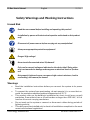
Safety Warnings and Working Instructions
Hazard Risk
Read the user manual before installing and operating this product!
Installation by person with electronical expertise and trained on this product
only!
Disconnect all power sources before carrying out any manipulation!
Always use appropriate protection equipment!
Danger! High voltage!
Never touch disconnected wires! Life hazard!
Only use for current/voltage as indicated on the device label! Doing other-
wise can cause device damage and may pose an electrical shock or fire haz-
ard!
Not properly tightened screws can cause a high contact resistance, lead to
overheating, and cause a fire hazard!
Warnings
• Read the installation instructions before you connect the system to its power
source.
• To prevent the system from overheating, do not operate it in an area that ex-
ceeds the maximum admitted ambient temperature of 55 °C.
• This product relies on the building’s installation for short-circuit (over current)
protection. Ensure that a fuse or circuit breaker no larger than 230 VAC, 16 A is
used on all current-carrying conductors.
• Do not work on the system or connect or disconnect cables during periods of
lightning activity.
• This device must be installed only in electrical installations compliant to the most
recent valid national regulations.

D-Box User's Manual English 3 / 76
tiko Energy Solutions AG IM-0007-0006 Rev. 10
• Device is intended for indoor use only.
• Ultimate disposal of this product should be handled according to all national
laws and regulations.
• Any usage of this device in a manner that does not conform to this manual spec-
ification can impair the provided safety protection.
Safety Instructions
Read these safety instructions carefully.
• Follow common household electrical safety practices.
• Read all cautions and warnings on the equipment.
• Disconnect this equipment from the socket before cleaning it. Do not use liquid
or sprayed detergent for cleaning. Use moisture sheet or cloth for cleaning.
• The openings on the enclosure are for air convection and protect the equipment
from overheating. Do not cover the openings.
• Do not pour any liquid into opening. This could cause fire or electrical shock.
• Do not open the enclosure of this product and/or alter this product in any way.
• Have the equipment checked by a service professional if one of the following
situations arises:
o The line is damaged.
o Liquid has entered the equipment.
o The equipment has been exposed to moisture.
o The equipment does not work properly, or you cannot get it to work
according to user’s manual.
o The equipment has been dropped or damaged.
o The equipment has obvious signs of breakage.
• Keep this equipment away from excessive or condensing humidity.
• Do not leave this equipment in an unconditioned environment. Temperatures
above 55 °C will damage the equipment.
• Keep this guide for later reference.
Feedback
You can submit comments via email to [email protected]
You can also submit your comments via regular mail by writing to the following address:
tiko Energy Solutions AG
Pflanzschulstrasse 7
CH-8004 Zürich
We appreciate your comments.

D-Box User's Manual English 4 / 76
tiko Energy Solutions AG IM-0007-0006 Rev. 10
Overview
Intended Use
The D-Box is a decentralized energy meter and switch to control electrical heaters. All D-
Boxes together require an M-Box (Gateway) to communicate to the back-end private
cloud. Each D-Box requires an external temperature sensor (REF CASTH-01.1004-01) to
know about the room it shall control.
D-Boxes and the accessories from the D-Box kit are to be only used in tiko Energy Solu-
tions AG authorized setups. They cannot be used standalone. Any installation or usage
which does not conform to tiko Energy Solutions AG setup is strictly forbidden. tiko Energy
Solutions AG is not responsible for any improper installation/usage of this device.
Features
The D-Box features:
• Relay: 230 V – 16 A
• Fil Pilote IN and OUT
• Status LEDs showing data link and device errors.
• A push button to perform different tests.
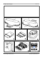
Package Content
Open the package and check that you have all the following items:
For Kit K01-CDK-01.1016-01-P1:
• Instruction manual (REF IM-0007-0013)
• D-Box (IMAGE 1 and IMAGE 2)
• Metal holder with screw holes and adhesive tape (IMAGE 6)
• Pre-wired socket (REF CDS-01-P1), see IMAGE 5
If any of the parts are incorrect, missing, or damaged, please contact the retailer where
you made your purchase. Keep the carton box, including the original packing materials, in
case you need to return the unit for repair.

D-Box User's Manual English 5 / 76
tiko Energy Solutions AG IM-0007-0006 Rev. 10
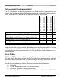
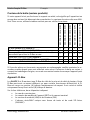
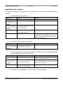
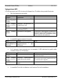
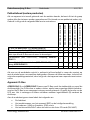
Package Content (Legacy Products)
In case your unit does not come with the metal holder, it belongs to the group of legacy
kits that are not produced anymore. Your package content will be different. In this case
use the following table to check:
K01-CDK-01.1014-01-P1
K02-CDK-01.1014-01-P1
K03-CDK-01.1014-01-P1
K01-CDK-01.1016-01-P1
K02-CDK3-01.1016-01-P1
D-Box (IMAGE 1 and IMAGE 2)
✓
✓
✓
✓
✓
Instruction manual (REF IM-0007-0013)
✓
✓
✓
✓
✓
A sealed bag of Velcro patches and/or double tape to
mount the D-Box to the wall
✓
✓
✓
✓
✓
Socket (REF CDS-01-P1), see IMAGE 3
✓
✓
✓
Pre-wired socket (REF CDS-01-P1), see IMAGE 5
✓
✓
Tap (REF CATA-01.1103-P1), see IMAGE 4
✓
✓
✓
If any of the parts are incorrect, missing, or damaged, please contact the retailer where
you made your purchase. Keep the carton box, including the original packing materials, in
case you need to return the unit for repair.
Device: D-Box
IMAGE 1 and IMAGE 2 show a D-Box from the plug side and from the button side. Your
D-Box may look differently, as for some electricity providers the D-Box comes in a cus-
tom design. (A) marks the location of the LED. It is hidden and only visible when on. (B)
marks the button.
On the bottom side, two labels are indicating:
• The manufacturer
• The device model number (REF) and current rating
• The hardware (HW) and firmware (FW) version
• The unique serial/MAC address as text and as Aztec 2D code (SN/MAC)

D-Box User's Manual English 6 / 76
tiko Energy Solutions AG IM-0007-0006 Rev. 10
Device: Socket
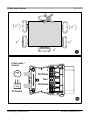
IMAGE 3 shows the socket. It is connected to the electrical wiring of the heater and of-
fers a socket to plug the D-Box. It features 5 screw terminals for the contacts and a strain
relief (IMAGE 7).
On the top cover is indicated
• The manufacturer
• The device model number (REF) and current rating
Device: Continuity Bridge (Tap)
IMAGE 4 shows the continuity bridge. If a customer decides not to take part in the tiko
cloud, the D-Box can be removed from the socket and the continuity bridge is engaged
to restore the original contacts for manual operation of the electric heater.
Accessory: Holder
IMAGE 6 shows the D-Box holder. It is mounted on the wall and holds the D-Box plugged
into the socket. This facilitates the handling of the D-Box, for example on disconnect or
replace: The device can first be brought out from behind the heater and then operated in
a more comfortable position.

D-Box User's Manual English 7 / 76
tiko Energy Solutions AG IM-0007-0006 Rev. 10
Installation
Installation by person with electronical expertise and trained on this
product only!
Do not install the device unless you have removed the main power sup-
ply (main breaker or fuses)!
IMAGE 17 shows possible D-Box locations around the heater. The best
position is bottom left, right or center. Under no circumstances install
the D-Box above the heater. This will result in thermal issues and my
damage the device!
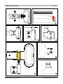
Installing the D-Box
Step 1
Remove power from the electrical panel.
Step 2
Unhook the heater from its holder and put it to the side.
Plan the location of the D-Box in advance. It should be in 2 – 3 cm of
the heater (IMAGE 10) and a permitted position (IMAGE 17). Use, for
example, a pencil to carefully mark the planned location.
Step 3
Disconnect the radiator from the wall.
If you own the Kit K03-CDK-01.1014-01-P1 or K01-CDK-01.1016-01-
P1, the D-Box socket is already equipped with a piece of cable on one
side.
The legacy kits that are not yet equipped with pre-wired socket need an
additional small piece of suitable cable. Ensure the cable is compliant.
Prepare the wires where necessary by crimping bootlace ferrules.
Step 4
Remove the cover from the socket. If you hold the socket like displayed
in IMAGE 18, clamp the phase coming from the wall/source into the top
terminal, and the phase going to the heater into the bottom terminal.
Step 5
Clamp the neutral wire coming from the wall/source and going to the
heater into the middle terminal. There is space on both sides of the
screw for two wires.
Step 6
If your heater supports Fil Pilote: hold the socket as displayed in IM-
AGE 18, clamp the Fil Pilote coming from the wall/source into upper
middle terminal and the Fil Pilote going to the heater into the lower mid-
dle terminal. A proper wiring is displayed in IMAGE 8.

D-Box User's Manual English 8 / 76
tiko Energy Solutions AG IM-0007-0006 Rev. 10
Step 7
Firmly tighten any unused terminal.
Step 8
Fasten the strain relief to prevent the wires in the terminal from being
pulled out.
Tighten again all clamp screws with enough torque. Insuffi-
cient clamping force can result in high contact resistance
that leads to device heating and can result in a fire hazard.
Step 9
Put back the cover of the socket.
Step 10
Engage the D-Box and the socket as displayed in IMAGE 9. Push the
two levers of the socket in order to open the safety shutter and plug in
the D-Box.
Pay attention to the orientation of the socket and D-Box
when plugging. The printed text on the socket and the top
side of the D-Box must be on the same side (see IMAGE 9).
Step 11
IMAGE 17 shows the permitted and prohibited positions for mounting
the D-Box.
It is forbidden to place the D-Box above the heater for ther-
mal reasons. The device could overheat. Preferred position
is below the heater or laterally below (IMAGE 17).
Ensure a distance of 2 cm – 3 cm between the heater and
the D-Box (IMAGE 10).
Depending on the mounting solution supplied with your unit, you will
need to proceed to either Step 11a or Step 11b.
If your device is equipped with the metal holder (IMAGE 6), please pro-
ceed with Step 11a.
If your device is equipped with an air-sealed bag containing 3 patches of
Velcro and/or double tape, please proceed with Step 11b.
Step 11a
The D-Box holder can be mounted with screws (preferred if the condi-
tion of the wall allows it) or with an adhesive tape. It can be installed in
all directions, including upside down (IMAGE 15 and IMAGE 16).
By means of screws:
Use two screws size 4x20 with countersunk head. Examples:
Wood/chipboard screw, screw with dowel.

D-Box User's Manual English 9 / 76
tiko Energy Solutions AG IM-0007-0006 Rev. 10
The type of screw must be appropriate for the correspond-
ing wall.
When using dowels, make sure that (i) the dowel size fits the
screw size and (ii) the type of dowel is appropriate for the
wall.
Fasten the holder in the desired location (IMAGE 12). Refer to IM-
AGE 17 for permitted and prohibited locations of the D-Box.
By means of adhesive tape:
The adhesive tape supplied with the holder is a Nano Suction Tape. Its
adhesive force is generated by nano-sized suction cups. It is adhesive-
free and does not dry out.
Peel off the protective film as shown in IMAGE 13. The permitted and
prohibited positions of the D-Box are shown in IMAGE 17. Press the
holder firmly into the desired position.
The wall must be free of dust. Otherwise, the dust will clog
the nano-sized suction cups and the holder will fall off
shortly after.
When pressing against the wall, ensure that you apply an
evenly distributed force of at least 15 kg. Unlike adhesive-
based tapes, the adhesion force of the Nano Tape depends
on the contact pressure.
After successfully mounting the holder, slide the D-Box (plugged into
the socket, see Step 10) into the holder (IMAGE 14).
tiko is not liable for damage caused by improper mounting
or due to defective condition of the building substance.
Step 11b
Open the sealed bag and place the patches onto the D-Box and socket
at the positions indicated in IMAGE 11.
Remove the protection foils and push the D-Box onto the wall at the
desired location. Refer to IMAGE 17 for permitted locations. Hold it for
several seconds.
The D-Box should now stay in place. If it seems loose, the glue on the
patches has been dried out due to bad storage conditions. Contact your
reseller to obtain fresh patches.

D-Box User's Manual English 10 / 76
tiko Energy Solutions AG IM-0007-0006 Rev. 10
The glue of the patches needs to dry for at least for 24
hours before reaching full strength. Do not unplug or move
the D-Box during this time.
Step 12
Lift the heater back to its hooks.
Step 13
Power on the system by enabling power in the electrical panel. Config-
ure the heater to the hottest possible level/temperature.
Step 14
To finalize the installation, all tiko devices must be configured using the
installation app. Remind that to each room with one or multiple D-Boxes
belongs a temperature sensor (REF: CASTH-01.1004-01).
Operation
Device Operation
There are two functions assigned to the button:
• Short press (min. 1 sec., less than 5 sec.) – test communication quality to the
Gateway. For the description of the LED, see section LED Explanation.
• Long press (more than 5 sec.) – Heater test. For details, please refer to the sec-
tion Heater Test.
The D-Box is subject to the control of the full system and operated by the Data Center
through the Gateway (M-Box). No user interaction is required.

D-Box User's Manual English 11 / 76
tiko Energy Solutions AG IM-0007-0006 Rev. 10
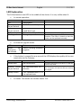
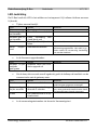
LED Explanation
The D-Box features one LED in the middle of the device. It is only visible when lit.
• In normal operation:
LED
Status
Notes
Off
Operational
Blinking yellow,
2x per second
No PLC connectivity
Blinking yellow,
1x per second
No connection to
cloud/back-end
Red
Power-on self-test failure.
For example, when wrongly wired
Blinking red
Emergency mode
Device is damaged or has hardware mal-
function. The relay is closed so that the
heater can be operated manually.
• In firmware upgrade mode:
LED
Status
Notes
Blinks yel-
low/green 2x
per second
Device running firmware
upgrade
• If the button is pressed for one second, the LED displays the quality of the com-
munication to the Gateway:
LED
Status
Notes
Steady Red
No connectivity
Since the last start of the device, it did not
receive any data.
Blinking yellow,
4x per second
No communication for 2
minutes
At least one data packet was received, but
for 2 minutes the device did not receive
any signal.
Steady Green
The communication is in
the optimal state
• In Heater Test mode: see section Heater Test.

D-Box User's Manual English 12 / 76
tiko Energy Solutions AG IM-0007-0006 Rev. 10
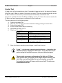
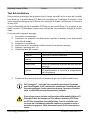
Heater Test
A long press of the button (more than 5 seconds) triggers a test of the electrical heater.
With this, the D-Box can check if the wiring is correct. The test is executed locally on the
D-Box and does not need any connectivity to the Gateway or the back-end.
The test is available for both Fil Pilote and Relay mode. To choose the correct mode, the
D-Box must have been properly configured in the install app.
The test consists of the following steps:
1. Switch the heater ON.
2. Wait for it to consume a certain amount of energy during a certain time.
3. Switch the heater OFF.
4. Ensure if the heater stops consuming.
5. Repetition of steps 1 to 4.
6. Display of the result:
LED
Status
Off
Test not running or stopped.
Blinking Green
Test in progress.
Steady Green
Test completed successfully.
Steady Red
The test failed during a switch.
Blinking Red
The test failed while trying to keep
the heater on or off.
7. Now the button must be pressed again to exit from the test.
If step 7 – exit the test by pressing again the button – is forgotten, the
LED will continue to display the result status. In case this step was for-
gotten during the installation process, just press the button again.
The test relies on a proper configuration of the Relay vs. Fil Pilote
mode of the D-Box. For example, if the Heater features Fil Pilote, but
the D-Box is set to Relay Mode, the test will complete successfully
(but maybe the heater will beep or switch on and off). The other way
around the test will fail.

D-Box User's Manual English 13 / 76
tiko Energy Solutions AG IM-0007-0006 Rev. 10
Uninstalling
The D-Box can be uninstalled in 3 different ways:
Decommissioning
In the backend, the D-Box can be disabled. In this case, a relay inside the D-Box is closed
in such way that the wires are bridged. The D-Box remains in place, but the heater can
be operated manually.
Continuity Bridge
The D-Box is removed from the socket. The socket is bridged using the Continuity Bridge
CATA-01.1103-P1) displayed on IMAGE 4.
Complete Uninstallation
Step 1
Remove power from the electrical panel.
Step 2
Unhook the heater from its holders and put it to the side.
Step 3
Unplug the D-Box, open the socket and unscrew all wires.
Step 4
Reconnect the wires from the heater to the wall/source again.
Step 5
If your unit is equipped with a metal holder, remove it.
If the holder is mounted by means of screw, unscrew the holder, and fill
the holes with putty.
If the holder is mounted with the Nano Tape, carefully and slowly rotate
the holder, until it starts to come off. Further twist and tilt the holder
until it comes off completely. Ensure the wall and/or paint is not dam-
aged. You might need to rub off remaining Nano Tape with your finger.
Step 6
Lift the heater back onto its holders and power on the system by ena-
bling power in the electrical panel.
Step 7
If the device remains property of tiko Energy Solutions AG or
its authorized reseller, it must be returned. Otherwise, the
ultimate disposal of a device shall be handled according to
national laws and regulations.

D-Box User's Manual English 14 / 76
tiko Energy Solutions AG IM-0007-0006 Rev. 10
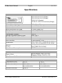
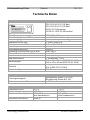
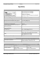
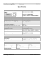
Specifications
Device Characteristics
Product Number
CD-01.1014-01-P1 (D-Box)
CD-01.1016-01-P1 (D-Box)
CDS-01-P1 (Socket)
CATA-01.1103-P1 (Continuity Bridge)
Input / Output Voltage
230 VAC ± 10%
Input / Output Relay Current
max. 16 A (not fused)
Input / Output Fil Pilote Current
max. 100 mA (fused)
Wire Specification for Load
1.5 mm2 (AWG 16)
Wire Specification for Fil Pilote
1.5 mm2 (AWG 16)
Frequency
50 Hz
Overvoltage Category
OVC II
Voltage of Breaker before D-Box
max. 240 V
Current of Breaker before D-Box
max. 16 A
Connectivity
PLC HomePlug GreenPHY
User Interface
1 push button, 1 LED
Dimensions
136 x 134 x 39 mm (REF CD-01.1014)
160 x 125 x 42 mm (REF CD-01.1016)
Weight
235 g (REF CD-01.1014)
251 g (REF CD-01.1016)
Max. Power Consumption
3 W
Metrology Characteristics
Power Meter
Active Energy: Class C (± 0.5%)
Reactive Energy: Class B (± 1%)
Min. Measurable Current
± 0.05 A
Operating Conditions
Storage Conditions
Temperature (min.)
-10 °C
-20 °C
Temperature (max.)
+55 °C
+70 °C
Relative Humidity
10% - 85%
no condensation
5% - 95%
no condensation
Maximum Altitude
2000 m
-

D-Box User's Manual English 15 / 76
tiko Energy Solutions AG IM-0007-0006 Rev. 10
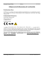
Obtaining the Declaration of Conformity
Intended Use
The D-Box is a custom single-phase energy meter and remotely controlled switch to be
only used in tiko Energy Solutions AG authorized setups.
Safety Information
tiko Energy Solutions AG
Pflanzschulstrasse 7
CH-8004 Zürich
The products CD-01.1014-01-P1, CD-01.1016-01-P1, CDS-01-P1 and – if part of the
kit – CATA-01.1103-P1 in the form as delivered conform to the provisions of the follow-
ing European directives: 2011/65/EU on hazardous substances, 2014/35/EU on low
voltage devices, 2014/30/EU on electromagnetic compatibility.
A copy of the declaration of conformity can be requested by writing to the postal ad-
dress or is available on http://um.tiko.energy/1014 or http://um.tiko.energy/1016 re-
spectively.

Betriebsanleitung D-Box Deutsch 16 / 76
tiko Energy Solutions AG IM-0007-0006 Rev. 10
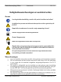
Sicherheitshinweise und Arbeitsanweisungen
Gefahrenrisiko
Lesen Sie das Benutzerhandbuch, bevor Sie dieses Gerät installieren und be-
dienen!
Installation ausschliesslich durch Person mit Sachkenntnis in Elektronik und
auf diesem Produkt geschult!
Trennen Sie alle Energiequellen vor der Bedienung dieses Geräts!
Benützen Sie immer angemessene Schutzkleidung!
Gefahr! Hochspannung!
Niemals lose Kabel berühren! Lebensgefahr!
Ausschliesslich für Gebrauch mit Strom/Spannung wie auf dem Geräteetikett
angegeben! Anderenfalls ist eine Beschädigung des Gerätes und damit ein
Stromschlag oder eine Brandgefahr möglich!
Nicht genügend angezogene Schrauben von Klemmen verursachen einen ho-
hen Kontaktwiderstand, welcher zu Überhitzung und Brandgefahr führen
kann!
Warnungen
• Lesen Sie die Installationsanweisungen, bevor Sie dieses Gerät an eine Strom-
quelle anschliessen.
• Um das System vor Überhitzung zu schützen, betreiben Sie es nicht in einer
Umgebung, welche die Temperatur von 55 °C übersteigt.
• Dieses Produkt ist auf das Vorhandensein eines Kurzschlussschutzes im Ge-
bäude angewiesen. Stellen Sie sicher, dass alle stromführenden Leiter durch eine
Sicherung oder einen Leistungsschalter nicht grösser als 230 VAC, 16 A ge-
schützt sind.
• Führen Sie keinesfalls Arbeiten am System oder an den Kabeln durch während
eines Gewitters.
• Dieses Gerät darf nur in elektrischen Installationen installiert werden, die den
jeweils aktuellsten gültigen nationalen Vorschriften entsprechen.

Betriebsanleitung D-Box Deutsch 17 / 76
tiko Energy Solutions AG IM-0007-0006 Rev. 10
• Gerät nur für den Innengebrauch.
• Endgültige Entsorgung dieses Geräts muss gemäss nationalen Gesetzen und
Vorschriften erfolgen.
• Jedweder Gebrauch dieses Geräts, welcher nicht dem Benutzerhandbuch ent-
spricht, kann den vorhandenen Schutz beeinträchtigen.
Sicherheitshinweise
Lesen Sie diese Sicherheitshinweise sorgfältig durch.
• Befolgen Sie gängige Sicherheitsregeln im Haushalt.
• Lesen Sie alle Hinweise und Warnungen auf dem Gerät.
• Entfernen Sie das Gerät aus der Steckdose, bevor Sie es reinigen. Benutzen Sie
kein flüssiges oder gespraytes Reinigungsmittel. Benützen Sie ein feuchtes Tuch
oder Stück Stoff zur Reinigung.
• Die Öffnungen im Gehäuse dienen der Luftzirkulation und schützen das Gerät
vor Überhitzung. Blockieren Sie nicht die Öffnungen.
• Leeren Sie keine Flüssigkeit in eine der Öffnungen. Dies kann zu einem Brand
oder Elektroschock führen.
• Öffnen Sie weder das Gehäuse dieses Gerätes noch modifizieren Sie es auf ir-
gendeine Weise.
• Lassen Sie das Gerät bei einem professionellen Service-Techniker überprüfen,
sollte eine der folgenden Bedingungen auftreten:
o Die Leitung ist beschädigt.
o Flüssigkeit ist ins Gerät eingedrungen.
o Das Gerät wurde Feuchtigkeit ausgesetzt.
o Das Gerät funktioniert nicht einwandfrei, oder es lässt sich nicht wie
im Benutzerhandbuch beschrieben betreiben.
o Das Gerät wurde fallengelassen oder beschädigt.
o Das Gerät weist sichtbare Spuren von Beschädigung auf.
• Halten Sie dieses Gerät von übermässiger oder kondensierender Feuchtigkeit
fern.
• Setzen Sie dieses Gerät nicht einer unkontrollierten Umgebung aus. Tempera-
turen über 55 °C werden das Gerät beschädigen.
• Bewahren Sie dieses Dokument für den späteren Gebrauch auf.
Rückmeldungen
Sie können Bemerkungen an [email protected] senden.
Ebenfalls können Sie uns Bemerkungen auf dem regulären Postweg senden, indem Sie
an diese Anschrift schreiben:
tiko Energy Solutions AG
Pflanzschulstrasse 7
CH-8004 Zürich
Wir freuen uns über Ihre Rückmeldung.

Betriebsanleitung D-Box Deutsch 18 / 76
tiko Energy Solutions AG IM-0007-0006 Rev. 10
Übersicht
Verwendungszweck
Die D-Box ist ein dezentraler Energiemesser und Schalter, um elektrische Heizungen zu
kontrollieren. Alle D-Boxen benötigen eine M-Box (Gateway), um mit der Backend-Cloud
zu kommunizieren. Jede D-Box benötigt einen externen Temperatursensor (REF CASTH-
01.1004-01) zur Kenntnis der Raumtemperatur für die Steuerung.
D-Boxen und Zubehör des D-Box-Kits sind für die ausschliessliche Verwendung in durch
tiko Energy Solutions AG autorisierten Installationen. Jegliche Installation oder Verwen-
dung, welche nicht den Richtlinien von tiko Energy Solutions AG entspricht, ist strikte ver-
boten. tiko Energy Solutions AG ist nicht verantwortlich für unsachgemässe(n) Installatio-
nen oder Gebrauch dieses Geräts.
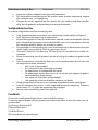
Merkmale
D-Box-Merkmale:
• Relais: 230 V – 16 A
• Fil Pilote EIN- und AUSGANG
• Status-LED zur Anzeige der Verbindung und von Gerätefehlern
• Ein Taster, um verschiedene Tests durchzuführen.
Packungsinhalt
Öffnen Sie die Verpackung und überprüfen Sie, ob folgende Artikel vorhanden sind:
Für das Kit K01-CDK-01.1016-01-P1:
• Gebrauchsanweisung (REF IM-0007-0013)
• D-Box (BILD 1 und BILD 2)
• Wandhalterung aus Metall mit Schraubenlöcher und Klebeband (BILD 6)
• mit Kabeln konfektionierte Kupplung (REF CDS-01-P1), siehe BILD 5
Sollten Artikel fehlen, falsch sein oder Beschädigungen aufweisen, kontaktieren Sie bitte
den Händler, bei dem Sie Ihren Kauf getätigt haben. Behalten Sie die Kartonschachtel
einschliesslich der Originalverpackung für den Fall, dass Sie das Gerät zur Reparatur ein-
senden müssen.

Betriebsanleitung D-Box Deutsch 19 / 76
tiko Energy Solutions AG IM-0007-0006 Rev. 10
Packungsinhalt (Vorgängerprodukte)
Falls Ihr Gerät nicht mit der Wandhalterung aus Metall geliefert wird, gehört es zur
Gruppe der Vorgängerprodukte. Ihr Packungsinhalt wird von der Beschreibung abwei-
chen. Verwenden Sie in diesem Fall die folgende Tabelle zur Überprüfung:
K01-CDK-01.1014-01-P1
K02-CDK-01.1014-01-P1
K03-CDK-01.1014-01-P1
K01-CDK-01.1016-01-P1
K02-CDK3-01.1016-01-P1
D-Box (BILD 1 und BILD 2)
✓
✓
✓
✓
✓
Gebrauchsanweisung (REF IM-0007-0013)
✓
✓
✓
✓
✓
Ein versiegelter Beutel mit Klettstücken und/oder Dop-
pelklebband, um die D-Box an der Wand anzubringen
✓
✓
✓
✓
✓
Kupplung (REF CDS-01-P1), siehe BILD 3
✓
✓
✓
mit Kabeln konfektionierte Kupplung (REF CDS-01-P1),
siehe BILD 5
✓
✓
Verschluss (CATA-01.1103-P1), siehe BILD 4
✓
✓
✓
Sollten Artikel fehlen, falsch sein oder Beschädigungen aufweisen, kontaktieren Sie bitte
den Händler, bei dem Sie Ihren Kauf getätigt haben. Behalten Sie die Kartonschachtel
einschliesslich der Originalverpackung für den Fall, dass Sie das Gerät zur Reparatur ein-
senden müssen.
Gerät: D-Box
BILD 1 und BILD 2 zeigen eine D-Box von der Stecker- und der Taster-Seite. Es ist mög-
lich, dass Ihre D-Box anders aussieht, da die D-Box für einige Energieversorger in einem
speziellen Design ausgeliefert wird. (A) markiert den Ort des LEDs. Es ist unter dem Ge-
häuse versteckt und nur sichtbar, wenn es leuchtet. (B) markiert den Taster.
Auf der Unterseite befinden sich zwei Etiketten mit folgenden Informationen:
• Hersteller
• Geräte-Modellnummer (REF) und Betriebsleistung
• Hardware- (HW) und Firmwareversion (FW)
• Eindeutige Seriennummer (MAC-Adresse) als Text und Aztec-Code (SN/MAC)

Betriebsanleitung D-Box Deutsch 20 / 76
tiko Energy Solutions AG IM-0007-0006 Rev. 10
Gerät: Kupplung
BILD 3 zeigt die Kupplung. Sie wird an die Stromkabel der elektrischen Heizung ange-
schlossen und ist mit einer Steckdose ausgestattet, um die D-Box einzustecken. Die
Kupplung beinhaltet 5 Schraubenklemmen für die Kabel und eine Zugsentlastung
(BILD 7).
Auf dem Deckel sind folgende Informationen angebracht:
• Hersteller
• Geräte-Modellnummer (REF) und Betriebsleistung
Gerät: Verschluss (Brücke)
BILD 4 zeigt den Verschluss. Möchte ein Kunde nicht an der tiko-Cloud teilnehmen, kann
die D-Box ausgesteckt und die Kupplung mit dem Verschluss überbrückt werden. Damit
sind die ursprünglichen Kontakte zur elektrischen Heizung wiederhergestellt, welcher
nunmehr manuell bedient werden kann.
Zubehör: Wandhalterung
BILD 6 zeigt die D-Box Wandhalterung. Sie wird an der Wand montiert und hält die in
der Kupplung steckende D-Box. Dies erleichtert die Handhabung der D-Box, z.B. beim
Ausstecken oder Austauschen: Das Gerät kann zunächst hinter der Heizung hervorgeholt
und dann in einer bequemeren Position bedient werden.
La pagina si sta caricando...
La pagina si sta caricando...
La pagina si sta caricando...
La pagina si sta caricando...
La pagina si sta caricando...
La pagina si sta caricando...
La pagina si sta caricando...
La pagina si sta caricando...
La pagina si sta caricando...
La pagina si sta caricando...
La pagina si sta caricando...
La pagina si sta caricando...
La pagina si sta caricando...
La pagina si sta caricando...
La pagina si sta caricando...
La pagina si sta caricando...
La pagina si sta caricando...
La pagina si sta caricando...
La pagina si sta caricando...
La pagina si sta caricando...
La pagina si sta caricando...
La pagina si sta caricando...
La pagina si sta caricando...
La pagina si sta caricando...
La pagina si sta caricando...
La pagina si sta caricando...
La pagina si sta caricando...
La pagina si sta caricando...
La pagina si sta caricando...
La pagina si sta caricando...
La pagina si sta caricando...
La pagina si sta caricando...
La pagina si sta caricando...
La pagina si sta caricando...
La pagina si sta caricando...
La pagina si sta caricando...
La pagina si sta caricando...
La pagina si sta caricando...
La pagina si sta caricando...
La pagina si sta caricando...
La pagina si sta caricando...
La pagina si sta caricando...
La pagina si sta caricando...
La pagina si sta caricando...
La pagina si sta caricando...
La pagina si sta caricando...
La pagina si sta caricando...
La pagina si sta caricando...
La pagina si sta caricando...
La pagina si sta caricando...
La pagina si sta caricando...
La pagina si sta caricando...
La pagina si sta caricando...
La pagina si sta caricando...
La pagina si sta caricando...
La pagina si sta caricando...
-
 1
1
-
 2
2
-
 3
3
-
 4
4
-
 5
5
-
 6
6
-
 7
7
-
 8
8
-
 9
9
-
 10
10
-
 11
11
-
 12
12
-
 13
13
-
 14
14
-
 15
15
-
 16
16
-
 17
17
-
 18
18
-
 19
19
-
 20
20
-
 21
21
-
 22
22
-
 23
23
-
 24
24
-
 25
25
-
 26
26
-
 27
27
-
 28
28
-
 29
29
-
 30
30
-
 31
31
-
 32
32
-
 33
33
-
 34
34
-
 35
35
-
 36
36
-
 37
37
-
 38
38
-
 39
39
-
 40
40
-
 41
41
-
 42
42
-
 43
43
-
 44
44
-
 45
45
-
 46
46
-
 47
47
-
 48
48
-
 49
49
-
 50
50
-
 51
51
-
 52
52
-
 53
53
-
 54
54
-
 55
55
-
 56
56
-
 57
57
-
 58
58
-
 59
59
-
 60
60
-
 61
61
-
 62
62
-
 63
63
-
 64
64
-
 65
65
-
 66
66
-
 67
67
-
 68
68
-
 69
69
-
 70
70
-
 71
71
-
 72
72
-
 73
73
-
 74
74
-
 75
75
-
 76
76


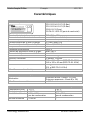
tiko CD-01.1014-01-P1 Manuale utente
- Tipo
- Manuale utente
- Questo manuale è adatto anche per
in altre lingue
- English: tiko CD-01.1014-01-P1 User manual
- français: tiko CD-01.1014-01-P1 Manuel utilisateur
- Deutsch: tiko CD-01.1014-01-P1 Benutzerhandbuch
- Nederlands: tiko CD-01.1014-01-P1 Handleiding
Documenti correlati
-
tiko K-Box A4 Digitalizing Energy Manuale utente
-
tiko Sense-3 Manuale utente
-
-
tiko CMB-01.1011-01-P1 Manuale utente
-
tiko GM-01.0013E Manuale utente
-
tiko CMM-01 Series Manuale utente
-
 tiko Class C Manuale utente
-
-
 tiko GM-01.0013M Manuale utente
-
tiko K-Box A6 Manuale utente


