Casella APEX Personal Sampling Pump Manuale utente
- Tipo
- Manuale utente

1
APEX SERIES
PERSONAL AIR SAMPLING PUMPS
& PUMP MANAGER SOFTWARE
(I.S. and Non I.S. Versions)
User Handbook
HB 3294-08
COPYRIGHT
The copyright in this document which contains proprietary information is vested in CASELLA CEL LIMITED. The
contents of this document must not be used for purposes other than that for which it has been supplied or
reproduced or disclosed wholly or in part without the prior written permission of CASELLA CEL
CASELLA CELCASELLA CEL
CASELLA CEL
CASELLA CEL
Regent House
Wolseley Road
Kempston
Bedford
MK42 7JY
Tel: 00 44 1234 844100
Email: info@casellameasurement.com
www.casellameasurement.com
Casella USA
17 Old Nashua Rd
Amherst
NH03031
USA
Tel: 00 1 800 366 2966
Email: info@casellausa.com
www.casellausa.com

2
WARNINGS !
All Versions:
Apex and Apex Pro air sampling pumps are designed to be robust, however they
should not be dropped or subjected to mechanical shock. DO NOT suck in water,
or highly saturated or corrosive gases. Failure to comply will render the
warranty invalid.
These instruments are designed as personal sampling units operating from
internal batteries. They MUST NOT be powered for prolonged periods from
external supplies.
They contain no user serviceable parts and if a fault is suspected the instrument
must be returned immediately to Casella CEL or to a Casella CEL Approved
Agency for repair.
The warranty DOES NOT extend to cleaning or general servicing of the
instrument.
Intrinsically Safe Versions:
DO NOT ATTEMPT TO DOWNLOAD data via the IR port in a hazardous area.
Use only a CASELLA APPROVED Intrinsically Safe battery pack. Part Number
182013C (4.8 V, 1.7 Ah Nickel metal- hydride). Battery packs for the non
intrinsically safe versions MUST NOT be connected to the intrinsically safe
versions.
DO NOT use the battery charger in a hazardous area.
DO NOT use the equipment if the outer case of the instrument , or the battery
pack is cracked or damaged in any way as this invalidates the intrinsically safe
certification.
The user MUST ENSURE that the I.S. rating of the pump to be used is suitable
for the I.S. rating of the intended hazardous area.
To prevent ignition of flammable or combustible atmospheres, DISCONNECT
POWER before servicing.
DO NOT service while in a hazardous area.
Instructions specific to hazardous area installations (reference
European ATEX Directive 94/9/EC, Annex II, 1.0.6.):
The equipment may be used with flammable gases and vapours with apparatus
Groups IIA, IIB and with temperature classes T1, T2, T3 and T4.
The equipment is certified only for use in ambient temperatures in the range
+5
o
C to +40
o
C and should not be used outside this range.
The certificate marking are detailed in the rear of the handbook.
Repair of this equipment shall be carried out by the manufacturer or in
accordance with the applicable code of practice.
The certification of this equipment relies on the following materials used in its
construction:
High Impact PC- ABS/ Clear Polycarbonate/Acrylic.
If the equipment is likely to come into contact with aggressive substances, then
it is the responsibility of the user to take suitable precautions that prevent it
from being adversely affected, thus ensuring that the type of protection is not
compromised. (Aggressive substances e.g. solvents that may affect polymeric
materials.)
Suitable precautions e.g. regular checks as part of routine inspections or
establishing from the material’s data sheet that it is resistant to specific
chemicals.
Under certain extreme circumstances, the non-metallic parts incorporated in the
enclosure of this equipment may generate an ignition-capable level of
electrostatic charge. Therefore, when it is used for applications that specifically
require group II, category 1 equipment, the equipment shall not be installed in a

3
location where the external conditions are conducive to the build-up of
electrostatic charge on such surfaces. Additionally, the equipment shall only be
cleaned with a damp cloth.
SICHERHEITSHINWEISE
Apex und Apex pro Luftprobenpumpen sind robust konstruiert, sie sollten
jedoch keinen mechanischen Belastungen, Stuerzen unterworfen werden, und
duerfen nicht mit Wasser in Beruehrung kommen. Auch nicht mit aggressiven
und aetzenden Fluessigkeiten. Die Nichtbeachtung hat den Verfall der Garantie
zur Folge.
Die Sammelpumpen wurden fuer den Batteriebetrieb entwickelt. VERMEIDEN
SIE es die Instrumente laengere Zeit über einen Netzanschluss zu betrieben.
Geraete nicht oeffnen! Senden sie bei einer Stoerung das Instrument an Casella
oder einen der autorisierten Casella Handler zurueck.
Die Garantie erstreckt sich nicht aufReinigung und allgemeine
Wartungsarbeiten.
Vergewissem sie sich vor jedem geplanten Einsatz von der Funktionsfaehigkeit
des Geraetes.
LADEN SIE KEINE DATEN in kontaminierter Umgebung über die IR-Schnittstelle
herunter.
Benutzen sie ausschliesslich den Casella Batteriesatz (Artikel Nr. 182013C),
4,8V, 1,7 Ah, Nickelhydrid, Cadmium frei, schnell aufladbar. Die Batteriesaetze
duerfen nicht getauscht oder durch Fremdfabrikate ersetzt werden.
Benutzen sie das Ladegeraet NICHT in kontaminierten Bereichen.
Das Geraet darf nicht bei aeusserlichen Beschaedigungen oder schadhaften
Batteriesaetzen in Betrieb genommen werden. Die Sicherheit des Geraetes wird
dadurch beintraechtigt.
Anweisungen zur Installation in Gefahrbereichen (Europaeische
ATEX Direktive 94/9/EC, Anhang II, 1.0.6.):
Die Geraete koennen mit brennbaren Gasen und Daempfen, mit Apparaten der
Gruppen IIA, IIB und bei Temperaturen der Klassen T1, T2, T3 und T4 betrieben
werden.
Die Geraete sind für den Einsatz bei einer Umgebungstemperatur von +5
o
C bis
+40
o
C freigegeben und sollten nicht ausserhalb dieses Bereiches betrieben
werden.
Die Zertifikate sind am Ende des Handbuchs detailliert aufgelistet.
Reparaturen sollten nur vom Hersteller oder autorisierten Händlern durchgeführt
werden.
Die Zertifizierung der Geraete basiert auf den folgenden
Konstruktionsmaterialien:
Hoch stossfestes PC-ABS/reines Polykarbonat/Acrylic
Wenn das Geraet mit aggressiven Substanzen in Beruehrung kommt, ist der
Anwender dafür verantwortlich die erforderlichen Schutzmassnahmen zu treffen
um das Gerät vor Schaeden zu bewahren. (Aggressive Substanzen, z.B.
Loesungen koennen PC angreifen.)
Entsprechende Vorkehrungen wie z. B. Routine- inspektionen und die
Auswirkungen spezifischer chemischer Substanzen sind zu treffen, bzw. zu
beachten.
Unter bestimmten extremen Bedingungen können sich nichtmetallische Teile
innerhalb des Gehaeuses elektrostatisch aufladen. Bei Anwendung des Gerätes
nach Gruppe II, Kategorie1 darf das Gerae nicht in Bereichen betrieben werden
in denen die Moeglichkeit des Aufbaus einer elektrostatischen Aufladung

4
besteht.Zusaetzlich ist das Geraet mit einem feuchten Tuch zu reinigen
AVERTISSEMENTS !
Toutes les Versions:
Les pompes de prélèvement d’air Apex et Apex Pro sont conçues pour être
robustes, toutefois elles ne doivent pas être jetées ou soumises au choc
mécanique. Ne pas utiliser dans l’eau, dans des lieux fortement saturés ou à
des fortes expositions de gaz corrosif. Le non-respect de ces instructions
rendra la garantie nulle.
Ces instruments sont conçus car des unités d’échantillonage individuel
fonctionnant à partir de batteries. NE DOIVENT PAS ÊTRE actionnées pendant
des périodes prolongées des approvisionnements externes.
Si l’utilisateur suspecte un défaut, l’instrument doit être retourné
immédiatement à Casella CEL ou à une agence approuvée par Casella pour la
réparation. La garantie ne concerne que les pièces détachées hors maintenance
des appareils.
Versions de sécurité intrinsèques:
N’essayez pas de télécharger des données par l’intermédiaire du port IR dans
une aire dangereuse.
Utilisez seulement les batteries intrinsèques validées par Casella. Numéro de
la pièce: 182013Ç (norme universelle 4,8 V, 1,7 Ah nickel-metal hydride). est
chargé in situ. Les batteries non intrinsèques ne peuvent être utilisées avec
des pompes intrinsèques.
Le chargeur de batterie ne doit pas être employé dans un secteur dangereux.
L’équipement ne doit pas être employé si le couvercle externe de la batterie est
endommagé car la sécurité intrinsèque de l’instrument ne sera pas forcément
assurée.
Les utilisateurs doivent toujours s’assurer que les pompes de prélèvement
conviennent aux règles de sécurité intrinsèque pour l’emplacement prévu avant
l’emploi.
Instructions spécifiques à l’installation dans des zones
dangereuses (reference European ATEX Directive 94/9/EC, Annex II,
1.0.6.):
L’équipement peut être utilisé avec les gaz et les vapeurs inflammables avec les
groupes d’appareils IIA, IIB et avec une température de classe T1, T2, T3 et T4.
L’équipement est seulement certifié pour l’utilisation dans des températures
comprises entre +5
o
C à +40
o
C et ne doit pas être utilisé en dehors de cette
gamme.
L’inscription du certificat est détaillée à l’arrière du manuel.
La réparation de cet équipement sera effectuée par le fabricant ou
conformément aux règlements et aux usages appropriés.
La certification de cet équipement se fonde sur les matières suivantes
employées dans sa fabrication :
High Impact PC- ABS/ Clear Polycarbonate/Acrylic.
Si l’équipement est susceptible d’entrer en contact avec des substances
agressives, alors il est de la responsabilité de l’utilisateur de prendre les
précautions nécessaires pour empêcher la dégradation de l’appareil, et de ce fait
s’assurant que le type de protection n’est pas compromis.
Des substances agressives comme les solvants peuvent affecter des matériaux
polymères
Des contrôles réguliers doivent être effectués par des inspections courantes ou
par l’établissement d’une fiche technique du matériel spécifiant sa résistance à

5
certains produits chimiques.
Dans certaines circonstances extrêmes, les pièces non métalliques incorporées
dans la fermeture de cet appareil peuvent produire un seuil explosif de charge
électrostatique. Par conséquent, quand il est employé pour des applications qui
exigent spécifiquement le groupe II, appareil de la catégorie 1, l’équipement ne
sera pas installé dans un endroit où les conditions externes favorisent le
développement de la charge électrostatique. De plus, l’équipement sera
seulement nettoyé avec un tissu humide.
ADVERTENCIAS !
Versión con standard:
Los muestreadores personales Apex y Apex Pro están diseñados para ser
robustas, sin embargo no deben ser sometidas a impactos o ser golpeadas. No
sumergir en agua o gases altamente saturados o corrosivos. El incumplimiento
de estas recomendaciones puede invalidar la garantía.
Estos equipos están diseñados como unidades de muestro personal que
funcionan con baterías internas. NO DEBEN utilizarse conectadas a red
eléctricia.
Los equipos no contienen componentes susceptibles de cambio por parte del
usuario. En caso de detectar cualquier fallo o avería se deberá enviar el equipo
directamente a Casella.
La garantía no incluye la limpieza del equipo ni cualquier otra tarea de
mantenimiento general del mismo.
Versión con seguridad intrínseca:
No intente descargar datos vía el puerto IR en área peligrosa.
Utilice solamente baterías con seguridad intrínseca de Casella. Número de
Referencia: 182013C (estándar universal 4,8 V, 1,7 Ah niquel-meta-hidruro). Se
carga in situ. Las baterías para las versiones sin seguridad intrínseca no se
pueden utilizar con las versiones con seguridad intrínseca.
El cargador de batería no se debe utilizar en un área peligrosa.
El equipo no debe ser utilizado si la carcasa externa de la batería está rota o
dañado de cualquier manera ya que esto puede invalidar la seguridad intrínseca
del instrumento.
Los usuarios deben asegurarse siempre antes de su utilización que el grado de
protección del equipo en las bombas del muestreo sea el adecuado en relación
con el grado de protección requerido del sitio previsto para realizar el muestreo.
Instrucciones específicas sobre instalaciones en áreas peligrosas
(referencia Directiva Europea ATEX 94/9/CE, Anexo II, 1.0.6.):
Este equipamiento puede utilizarse con gases y vapores inflamables
pertenecientes a los grupos IIA y IIB, y con temperaturas superficiales máximas
clases T1, T2, T3 y T4.
Este equipamiento únicamente está certificado para su uso a temperatura
ambiente en el rango de temperaturas de +5
o
C a +40
o
C y no debe utilizarse fuera
de este rango.
El certificado de marcado del equipo se encuentra detallado al final del manual
de instrucciones.
La reparación del equipo debe llevarse acabo por el fabricante o de acuerdo con
el código de prácticas aplicable.
La certificación de este equipo está basada en los siguientes materiales
utilizados en su construcción:
Carcasa de alto impacto de policarbonato PC- ABS
Si es probable que el equipo entre en contacto con sustancias agresivas,

6
entonces es responsabilidad del usuario tomar las precauciones pertinentes para
prevenir efectos adversos que pudieran afectarlo, de forma que se asegure que
el tipo de protección no quede comprometido.
Sustancias agresivas: disolventes que pueden afectar a los materiales polímeros.
Precauciones adecuadas: comprobar regularmente como parte de la rutina de
inspección o establecer en la ficha de datos del material que es resistente a
compuestos químicos específicos.
Bajo ciertas circunstancias extremas, las partes no metálicas incorporadas en la
envolvente de este equipo pueden generar una ignición del orden de una carga
electrostática. Por consiguiente, cuando se use para aplicaciones que
específicamente requieren equipamiento categoría 1, grupo II, el equipo no
deberá colocarse en una zona en la que las condiciones externas contribuyan a
la generación de carga electrostática en su superficie. Adicionalmente, el equipo
solo deberá limpiarse con un paño húmedo.
AVVERTIMENTI !
Pumpe standard:
Le pompe di campionamento aria Apex e Apex Pro sono state progettate e
costruite per essere robuste e resistenti; tutavia non devono venire a contatto
con acqua o subire colpi / urti meccanici. NON devono essere immerse in acqua,
nè utilizzate in ambienti saturi e in presenza di gas corrosivi. In questi casi, cade
ogni diritto di garanzia.
Gli strumenti sono stati progettati per essere campionatori personali,
funzionanti con batterie interne. Pertanto NON DEVONO ESSERE ALIMENTATE
dall’esterno per periodi di tempo prolungati.
Apex e Apex Pro non contengono parti sostituibili dall’utente e se un difetto è
ritenuto sospetto lo strumento deve essere restituito immediatamente a Casella
CEL o ad un distributore autorizzato Casella CEL per la riparazione.
La garanzia non puo’ essere estesa alle operazioni di pulizia o all’assistenza
generale dello strumento.
Versioni a Sicurezza Intrinseca (I.S.):
Non si devono scaricare i dati via porta IR in zona pericolosa.
Utilizzare soltanto il pacco batteria CASELLA a Sicurezza Intrinseca, codice:
182013C (Standard 4,8 V, 1.7 Ah NiMH) caricata in situ. I pacchi batteria per
versioni non I.S., non possono essere usati con campionatori I.S.
I caricabatteria non devono essere usato in una zona pericolosa.
Il campionatore non deve essere usato se lo chassis esterno o il pacco batteria è
fessurato o risulta danneggiato in qualche modo, poichè questo invalida la
Sicurezza Intrinseca dello strumento.
Prima dell’uso, gli utenti devono accertarsi sempre che il tipo di classificazione
dei campionatori I.S. sia adatto al tipo di zona pericolosa.
Istruzioni specifiche per installazioni in aree pericolose (con
riferimento alla Direttiva Europea ATEX 94/9/EC, All. II, 1.0.6.):
L’apparecchiatura può essere utilizzata con gas e vapori infiammabili con
apparati di Gruppo IIA e IIB, e con temperature di classe T1, T2, T3 e T4.
L’apparecchiatura è certificata solo per l’uso con temperature ambientali
comprese tra +5
o
C e +40
o
C, e non deve essere impiegata al di fuori di questi
limiti.
I dettagli relativi alla certificazione si trovano sul retro del manuale di istruzioni.
Ogni intervento di riparazione sulla presente attrezzatura deve essere effettuato
dal produttore o in accordo con il relativo codice di pratica.
La certificazione della presente attrezzatura si basa sui seguenti materiali

7
utilizzati per la sua costruzione:
Policarbonato ad impatto elevato PC- ABS/ trasparente
Nel caso probabile in cui l’apparecchiatura possa venire a contatto con sostanze
aggressive (ad esempio: solventi che possono danneggiare i materiali
polimerici), è responsabilità dell’utilizzatore prendere adeguate precauzioni (ad
esempio: controlli regolari effettuati come parte integrante delle ispezioni di
routine o l’accertarsi, attraverso la scheda tecnica del materiale, della sua
resistenza a specifici agenti chimici), che la proteggano da eventuali danni, in
modo da assicurare che la protezione non venga compromessa.
In particolari condizioni estreme, le parti non metalliche incorporate nella cassa
della presente apparecchiatura potrebbero generare livelli di carica
elettrostatica che potrebbero portare a fenomeni di ignizione. Perciò, quando
usata in applicazioni che richiedono specificamente attrezzature di Gruppo II,
categoria 1, l’apparecchiatura non deve essere installata in luoghi nei quali le
condizioni esterne sono favorevoli all’accumulo di cariche elettrostatiche sulle
superfici. Inoltre, l’apparecchiatura deve essere pulita unicamente con un panno
umido.

8
CONTENTS
1. INTRODUCTION 9
1.1 Control Keys 10
1.2 Display Symbols 11
1.3 Indicators & Display Messages 11
2. PREPARATION FOR USE 11
2.1 Charging the Battery 11
2.2 Switching the Instrument On / Off 13
2.2.1 Hold Mode 13
2.2.2 Manual Reset (Clear Current Sample) 14
2.3 Perform Single Point Calibration (Set Flow) 14
2.4. Configuration Mode 15
3. MANUAL OPERATION 16
3.1 Run Mode 16
3.2 Flow Restriction 16
3.3 Bag Mode 17
3.4 Use With Low Flow Adaptor 17
3.5 Fixed Duration Sampling (DUR) 17
3.6 Locking the Keypad 18
4. ADDITIONAL SAMPLING MODES AVAILABLE
ONLY TO THE APEX PRO AND APEX PRO I.S. 18
4.1 TWA Sampling Mode 18
4.2 User Program Modes 20
5. CALIBRATION MODE 20
6. PUMP MANAGER SOFTWARE 21
6.1 Pump Manager Introduction 21
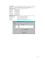
6.2 Software Installation / Un-installation on Windows
TM
95, 98, ME, NT 4, XP & 2000 21
6.3 Establishing Infrared (IR) Communication 22
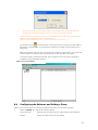
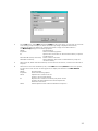
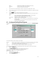
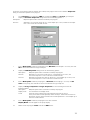
6.4 Configuring the Software and Adding a Pump 23
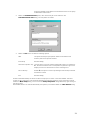
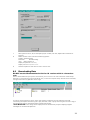
6.5 Downloading Data 26
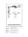
6.6 Inspecting Data, Adding Supplementary Information and Printing a Report 27
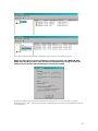
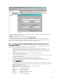
6.7 Creating and Loading Pump Programs 30
6.8 Error Messages 32
7. TECHNICAL INFORMATION 32
7.1 Pump Model Specification 32
7.2 Pump Performance 33
7.3 CE Compliance 33
7.4 Intrinsically Safe (I.S.) Versions Approvals 33
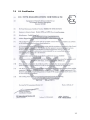
7.5 I.S. Certification 34
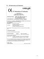
7.6 EC Declarations of Conformity 35
8. SERVICING 37
8.1 Maintenance 37
8.2 Fault Finding 37
8.3 Ordering Information 37
Flow Diagram 39

9
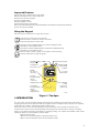
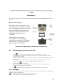
Improved Features
¤ Small size due to space-saving pump design
¤ Real-time display of flow rate on large LCD
¤ Direct flow control via keypad
¤ Multi language display
¤ Programmable run timer
¤ Data downloading via Infrared link
¤ Set up and data download of Advanced Models controlled by Pump Manager Software
¤ Two I.S. Versions available
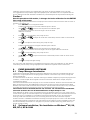
Using the Keypad
Manual control is exercised via a simple four key pad.
Press once to switch the instrument ON,
Press and hold a moment to cancel a command,
Press and hold down to switch OFF.
Scroll up through available options or increase a displayed value.
Hold-down to use repeat function.
Scroll down through available options or decrease a displayed value.
Hold-down to use repeat function.
Press to accept a value or option, for example to start the pump,
Press and hold-down to stop the pump.
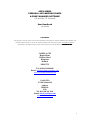
Figure 1: The Apex
1.INTRODUCTION
For many years, the name Casella has been associated with the design and manufacture of personal air
sampling pumps for the occupational health and hygiene market. The Apex series of pumps is an improved
replacement for models in the highly successful Vortex range.
These instruments use an efficient diaphragm pump whose flow rate is precisely maintained using
automatic flow control circuitry (Patent pending). The pump draws contaminated air through a sampling
head at a rate determined by the head design or sampling strategy. Four models are available. Check model
identity by referring to the the label on the rear panel.
Apex (standard model),
Apex Pro (can be downloaded and programmed by a PC),
Apex I.S. (Intrinsically Safe version of the standard model),
PROG.
SET FLO
o
C
L/min
RESET
CAL
I.R.
Inlet nozzle
Covered
outlet nozzle
Start/Stop
pump,
also acts as
an Enter key
Infra red port
Red LED
blocked flow/
fault indicator
Green LED
pump running
indicator
Scroll up
through available
options,
or increase
displayed value
Scroll down
through available
options,
or decrease
displayed value
On/Off
also acts as
cancel key
02022

10
Apex Pro I.S. (Intrinsically Safe version of the Apex Pro).
Please consult Casella CEL for information about upgrading a standard model to an Apex Pro or an Apex I.S.
to an Apex Pro I.S. The instrumentation is available as individual pumps or as complete kits with the
appropriate accessories to suit particular applications and is supported by our training and service facility at
Bedford.
The Apex was developed to provide sampling capabilities between 5 ml/min and 5 l/min (4 l/min for I.S.
versions), suitable for a wide range of applications including solvent fumes, asbestos clearance and
personal sampling of dusts. Apex pumps are ideally suited to many of the “Total” and “Respirable” dust
sampling techniques detailed in the U.K. Health and Safety Executive’s publication MDHS14, and in other
reference methods.
The information contained in this handbook relates only to the operation of Casella CEL sampling equipment
and is not intended to advise or influence your adopted sampling strategy. For advice on appropriate
sampling methods, refer to local legislation and guidelines as dictated by the relevant national and regional
health and safety organisations.
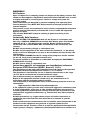
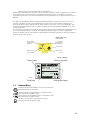
Inlet nozzle
Outlet nozzle
(for gas bag)
Red LED
Blocked flow/
Error indicator
Green LED
Pump running
indicator
0 2035
Infra red port
PROG.
SET FLO
o
C
L/min
RESET
CAL
I.R.
TEMP 19.48
2.5
Status Icons
Battery Condition
Flow Rate Varying Messages
02012
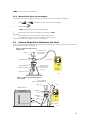
1.1 Control Keys
Switches the instrument ON/OFF, also acts as a cancel key.
Hold the key down to switch OFF.
Scrolls up through available options or increases a value.
Has a hold-down to repeat function.
Scrolls down through available options or decreases a value.
Has a hold-down to repeat function.
Accepts a value or option, starts/stops the pump.
Hold the key down to stop the pump.
Figure 2: Top view
Compartment
Figure 3: Display

11
1.2 Display Symbols
Halt - shows when pump is in Hold Mode , or blinks when halt option available.
Run - shows when pump motor is running.
Flow - indicates real flow monitoring is in progress.
Together indicates that the pump is paused but will start again
automatically, for example during TWA (time weighted average) or user prepared programs.
Indicates that all accumulated values displayed can be cleared back to zero (i.e. reset sample
volume and run time).
Resetting the store in this way ends the current sample run.
Warning - indicates flow outside permitted limits or other error
conditions.
This warning will be stored with the associated data on Apex Pro
versions.
Battery condition - The symbol empties as the power is drained and blinks when the output
approaches the minimum operating voltage.
Instrument temperature (user selected units).
Key pad is partially locked, the user can only start or stop the pump.
Key pad is fully locked.
1.3 Indicators & Display Messages
Green LED Flashes when the pump motor is running.
Red LED Flashes when the pump is unable to maintain the required
flow due to a restriction, or due to some other error.
PROGEnd Displayed when the pump has successfully completed a
programmed run.
BATTFAIL Warning when the voltage from battery pack falls below
the minimum operating level.
SERV dUE Warning after 2500 hours of operation that the instrument
should be serviced.
BUZZEr When activated, sounds warnings and indicates key strokes.
2. PREPARATION FOR USE
The following steps are required before the instrument can be operated.
Charge the Battery,
Perform a Calibration,
Connect the Sampling Head.
Manual operation is described in Chapter 4.
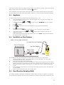
2.1 Charging the Battery
Three types of battery pack are available: two non-I.S. and one I.S. The battery pack connectors for non-I.S.
and I.S. are not compatible.
Standard 4.8 V, 2.7 Ah nickel-metal hydride pack that is charged in situ. Depending on loading, a fully
charged battery pack can provide up to 20 hours of continuous operation. (Refer to table 7.2 for details).
Non-rechargeable pack for emergency use only that takes four AA Alkaline dry cells. Depending on
battery type and flow rate, this can give up to approximately 8 hours of continuous operation. This pack
must not be used with I.S. Versions.(See Apex Lite).
I.S. version 4.8 V, 1.7 Ah nickel-metal hydride battery pack that is charged in situ. Depending on loading, a
fully charged pack can provide up to 20 hours of continuous operation. (Refer to table 7.2 for details).

12
DO NOT open the battery compartment of I.S. versions in a hazardous area.
DO NOT charge I.S. battery packs in a hazardous area.
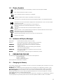
The battery pack is installed in a compartment located at the bottom rear of the instrument (Figure 4) A
captive screw locks the compartment cover.
There are two types of charger for non I.S and two
types of charger for I.S units. The single-way Fast
Charger (Part No. 182052B) and the 5-way chargers for
non I.S. use listed in Section 8.3 can be used only for
non I.S. versions. It will not charge I.S. versions.
I.S. versions must be charged only with the single-way
I.S. Charger (Part no. 182261B) or the 5-way chargers
for I.S. use listed in Section 8.3. For compliance
reasons, these chargers accurately control current
during charging, so take a slightly longer time to charge
the battery pack. These chargers can be used with non
I.S. versions, but will take longer to achieve a full
charge.
Charging is accomplished by inserting the complete
Apex unit into a drop-in charger (see Figure 5). All
battery chargers for Apex sampling pumps are
intelligent units with a safety time-out and standby
trickle charge mode to keep the pump ready for use.
The use of modern fast charge technology enables a discharged non I.S. pack to be fully recharged within 3
hours. Depending on filter type, a 1 hour charge can give a non I.S. pack sufficient power for 8 hours
operation. Similarly, a discharged I.S. pack can be fully recharged within 4.5 hours and depending on filter
type, a 1.5 hour charge can give it sufficient power for 8 hours operation.
A two colour LED on the charger shows the charging state. A constant red indicates that charging is taking
place while a constant green indicates that the full charge is being maintained by a trickle charge. (If neither
colour is shown while the pump is in the charger, a fault condition exists.)
When an Apex unit is initially placed in the charger unit, the LED will flash red for a few seconds before
changing to constant red. If the battery has been deeply discharged, it is possible that the LED will continue
to flash red for a longer period as the charger unit tries to condition the battery before entering the fast
charge state. If the flashing red continues for a prolonged period (e.g. a few hours) then a fault condition
exists. If when an Apex unit is placed in the charger, a constant green LED is shown, remove the Apex for
at least five seconds, then re-insert it. Faster replacement may have caused a false status indication.
To ensure the maximum life expectancy of rechargeable battery packs, DO NOT allow them to remain in a
fully discharged condition for extended periods of time.
When changing dry-cells in a non-rechargeable pack, it is recommended not to unplug the connector for the
battery pack lead.
Figure 4: Battery Compartment
Sealed
battery
pack
Connector
for battery
pack lead.
3-way for non-I.S.
5-way for I.S.
Hole for
captive
screw
Padding
Battery
compartment
v04018
Battery
compartment
cover
Casella CEL
Ni-MH Battery Pack

13
The following additional instructions must be read when using Apex Lite Pump
versions.
WARNINGS !
Apex Lite Versions are not intrinsically safe and must not be used in Hazardous Zoned
areas.
Batteries and charging:
Apex Lite versions operate from 4 x AA
dry cell batteries, so no charger is required.
AA sized NimH rechargeable cells can also
be used in the holder if preferred but no
charging will take place if the units are
placed in the Apex charger base
(182052B).
To convert the Lite version to a
rechargeable version purchase the
rechargeable battery pack 182073B insert
in place of the dry cell battery pack and
place in charger base 182052B.
Do not insert pump using dry cells into any recharging base.
2.2 Switching the Instrument On / Off
1. Press until the instrument display is activated to switch the instrument ON.
The display shows all segments, followed by the model name and firmware version number
before entering Hold Mode.
On Apex Pro versions only, the day-of-the-week and the time-of-day are also displayed during the
start up cycle.
If the display has incorrect contrast, shows messages in an unwanted language or offers
unexpected measurement units, make changes as described in Section 2.4.
2. Press and hold to switch OFF.
While the key is pressed, the display shows a count down in seconds ,until the instrument
switches off and the screen becomes blank.
If is released before the countdown has finished, the instrument remains ON.
2.2.1 Hold Mode
When the instrument is ON, but the pump is not running nor a program being executed, it is in Hold Mode,
where the display cycles between:
TIME Accumulated run time since the instrument was last reset.
VOL Accumulated volume sampled since it was last reset.

14
TEMP Current internal air temperature.
2.2.2 Manual Reset (Clear Current Sample)
To clear any accumulated sample duration and volume, the instrument must be in Hold Mode.
1. Press or sufficient times to make blink on the display.
2. Press and hold .
A CLR message and countdown will be displayed.
3. Hold the key down until the countdown is complete and CLR
disappears.
On the standard unit, all accumulated values will be cleared.
On the Apex Pro, data from any current event is stored and the
sample (run) terminated ready for a new run to be started.
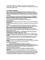
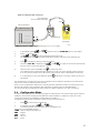
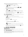
2.3 Perform Single Point Calibration (Set Flow)
Attach a sampling head and flow tube or other flow-measuring device to the pump’s inlet nozzle to measure
the actual flow as shown in Figures 6 - 8.
TEMP 19.48
2.5
02023
Clamp
Clamping Studs
Apex Pump
Rotameter Float
(Read flow rate
from the top of
the float)
Flowmeter Stand
Rotameter Tube
Sampling Head
Connecting Hose
(5 mm nominal
internal dia.)
TE MP 19 .48
2.5
02040
Clamp
Clamping
studs
Stand
Sampling
head
Connecting tube
(5 mm nominal internal dia.)
Flow
Flow
Outlet
Digital Flow meter
Apex Pump
Dry Cal
®
Pr imary Flow Meter
Figure 6: Calibration with rotameter
Compartment
Figure 7: Calibration with digital calibrator
Compartment

15
02041
Flow
Flow
Outlet
Apex Pump
Cyclone
Sampling Head
Dry Cal Flowmeter
Connecting tube
(5 mm nominal internal dia.)
Dry Cal
®
Primar y Flow Mete r
TE MP 19 .48
2 .5
1. In Hold Mode, press or several times until FLOW SEt blinks on the display.
2. Press to select it.
3. Use and to set the required sampling flow rate.
As a general rule, the pump should be calibrated to the flow required for the proposed task.
3. Press to accept the setting. The pump will start.
4. As soon as CAL SEt is displayed, use and to adjust the actual flow measured by
the flow meter to match the set point.
5. When the flow rate is acceptable, press to accept the value.
This calibration point will be saved and used by the pump in all future samples made at this flow.
If no control key is pressed within 30 seconds, the pump will revert to Hold Mode automatically.
6. If it is decided not to save this calibration, press and hold for a moment to abort and return to
Hold Mode.
The combination of automatic flow control and intelligent internal calibration procedures can substantially
reduce the number of calibration points required.
When a more comprehensive calibration is required, the basic calibration can be fine-tuned during normal
operation by making further single-point flow calibrations at specific flows as described above.
For information about recalibrating the whole range of an Apex or Apex Pro unit, refer to Chapter 5.
2.4 Configuration Mode
This allows basic settings such as display language and measurement units to be changed, gives access to
Calibration and Duration modes, plus the additional modes available to an Apex Pro. When the current
configuration settings are acceptable, proceed directly to Chapter 3.
Configuration Mode can be activated only while switching the instrument on.
1. Press to switch the instrument ON.
2. Immediately hold both and down.
The following series of configuration options is displayed. The
settings that are adjustable will blink.
LANG Sets the display language from:
ENG English,
FRA French,
DEU German,
ITA Italian,
Figure 8: Calibration with cyclone head

16
ESP Spanish,
DAN Danish.
TEMP Sets the temperature display units asCentigrade or Fahrenheit.
VOL Sets the volume display mode to Auto or m
3
Auto displays volumes below 1000 litres in litres and above this as m
3
.
m
3
always displays volumes in m
3
.
BUZZEr Sets an audible alarm to:
OFF No alarm,
Err Any error sounds the alarm,
On Any error or key press sounds
the alarm.
PROG Mode Gain access to program features, including
programmable run times on the standard unit and all programmable features on the Apex Pro.
ON Makes any advanced program features available,
OFF Hides any advanced program features.
LIFE Read-only message that shows the total run time for the pump. It can be be used to
determine maintenance schedules.
LCD Sets the LCD contrast.
Use to increase the value (make darker) and to decrease (make lighter).
CAL SET
Activates Calibration Mode, which allows the entire calibration for the pump to be reset,
based on a two point calibration.
The instrument will have been accurately calibrated at the factory prior to delivery.
Therefore it is recommended that this operation be performed only as part of a routine
service or when specific fine tuning is required to ensure that any selected flow rate will
be as close to the true flow as possible.
NO Do not recalibrate the pump.
YES Recalibrate the pump.
For information about recalibrating the whole range of an Apex or Apex Pro unit, refer to Chapter 5.
3. Use or to make a change, then press to accept it and move to the next
option.
3. MANUAL OPERATION
3.1 Run Mode
1. To start sampling and enter Run Mode, press while in Hold Mode.
In Run Mode the display will cycle between, current duration of the sample, volume sampled, and
internal air temperature.
2. To stop sampling while in Run Mode, press and hold until the symbol stops blinking and
disappears.
The instrument will display and save the accumulated duration and sample values until manually
reset.
Clearing values by a manual reset to close the run sample upon completion of an event ensures
that all downloaded data will be conveniently arranged to correspond with the sample result.
3.2 Flow Restriction
If the input flow becomes restricted, both and the Red LED will flash to indicate a problem and if
enabled, the buzzer will sound. When the problem lasts for eight or more seconds, the pump motor will
switch itself OFF. After one minute, the pump will switch ON again in an attempt to determine whether the
problem has gone. When the problem remains for a further eight seconds, the pump will switch OFF and
remain off with the instrument still ON and displayed.
If the output flow is restricted, both and the Red LED will flash to indicate a problem and if enabled,

17
the buzzer will sound. When the problem lasts for three or more seconds, the pump motor will switch itself
OFF and remain OFF with the instrument still ON and displayed.
Normal operation cannot be resumed until the flow restriction has been removed. When the restriction is
removed, the pump may start again automatically; if it does not, switch the Apex unit OFF then ON again.
3.3 Bag Mode
This allows the pump to fill a gas bag and stop automatically when it is full.
1. Use a suitable length of 5 mm (nominal internal diameter) tubing to connect the gas bag to the
pump outlet shown in Figure 2.
2. In Hold Mode, press or several times until FLOW SEt blinks on the display.
3. Press to select it.
4. Use to set the flow to less than 0.8 litres/min. The pump enters Bag Mode.
5. Press to start the pump.
The display will show BAG and a percentage flow, with no volume or time information.
6. Once the pump has started, and may be used to change the flow rate to a
different percentage.
When the back-pressure from the bag indicates that it is full, a FULL message will be displayed
and the pump stops automatically.
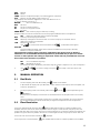
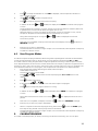
3.4 Use With Low Flow Adaptor
Outlet
Dry Cal Flowmeter
Dry Cal
®
Primary Fl ow Meter
v04019
Flow
Apex
Pump
Sorbent Tube
in Tube Holder
TEMP 19.4 8
2.5
Flow
Constant Pressure Regulator
Low Flow Adaptor
This enables the instrument to be used with sorbent tubes at flows down to 5 millilitres/min.
1. Connect the inlet of an Apex unit to a flow meter such as the Defender or Dry flow meter
and calibrate the flow rate to 1.5 litres/min.
2. Stop the pump and disconnect the flowmeter.
3. Starting from the Apex inlet, connect the following: constant pressure regulator, low flow adaptor,
sorbent tube holder and a low flow flow meter such as the Dry Flow or Dry Cal shown in Figure 9.
4. Break both ends off a sorbent tube and put it in the holder with the arrow pointing towards the
pump.
5. Start the Apex pump and adjust the flow to the required rate using the screw on the side of the
low flow adaptor.
6. Perform the measurements using a fresh sorbent tube.
3.5 Fixed Duration Sampling (DUR)
This mode is available on both Apex and Apex Pro models to allow the pump to sample for a fixed period,
then switch off automatically when the period has elapsed. This feature is useful where a stated flow rate
Figure 9: Low flow adaptor arrangement

18
must be sampled for a long period. The duration of the run can be set from the instrument keypad.
On Apex Pro, the duration can also be set via Pump Manager software.
1. Switch Program Mode ON and accept it as described in Section 2.4.
The instrument reverts to Hold Mode.
2. Press or several times until DUR blinks on the display.
3. Press to select it.
The programmed duration blinks to indicate it can be changed by and .
Run durations between 3 minute and 1 hour can be set in 1-minute steps and durations
between 1 and 25 hours in 10-minute steps.
4. Make changes to the duration as necessary.
5. Press to accept the duration and start sampling.
In addition to the symbol, the display shows PROG. to indicate that a program is active.
While the program is running, the display cycles through current run time, volume sampled, air
temperature, and programmed duration.
Once completed, the pump will switch OFF and the display show and a PROGEnd message.
6. Press any key to return the pump to Hold Mode.
3.6 Locking the Keypad
The keypad may be partially or fully locked to prevent unauthorised tampering with the instrument settings.
The keypad can also be locked in the Program Modes.
1. Press three times within 2 seconds to activate Partial Lock Mode.
The symbol is displayed, the counters and flow rate cannot be changed, so the only keypad
options available are:
Start/stop sampling,
Switch the pump OFF,
Unlock Partial Lock (Press three times within 2 seconds),
Select full lock.
2. While the pump is running (sampling), press three times again
within 2 seconds to activate Full Lock Mode.
The symbol is displayed, the pump cannot be switched OFF and the only available keypad
option is to release Full Lock.
3. Press three times within 2 seconds while in Full Lock Mode to fully release the control keys.
(Similarly, while the pump is not running (sampling) in Partial Lock Mode, press three times
within 2 seconds to fully release the control keys.)
4. ADDITIONAL SAMPLING MODES
AVAILABLE ONLY TO THE APEX PRO
AND APEX PRO I.S.
These modes are available when Program Mode on an Apex Pro or Apex Pro I.S. has been enabled from
within Configuration Mode as described in Section 2.4.
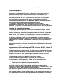
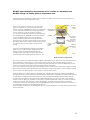
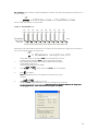
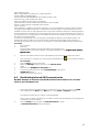
4.1 TWA Sampling Mode
Time weighted average (TWA) mode allows the pump to sample for a fixed percentage of a specified run
time. The instrument calculates the required ON/OFF cycle automatically to spread the total sample time
evenly over the entire run time as shown in Figure 10.
This feature is useful when the requirement is to sample a stated volume of air over the course of a long
period or for prolonged sampling scenarios.

19
For example, when 10 litres must be sampled over an 8-hour work shift, the pump flow can be set to run
at a flow rate of:
= 0.021 litres / min = 21 millilitres / min
10
8 x 60
For the whole shift, which is a very low flow.
On
1 min
On
1 min
On
1 min
On
1 min
On
1 min
On
1 min
On
1 min
On
1 min
On
1 min
On
1 min
02011
Run: 480 min
Exp: 10 min
TWA: 2%
Off
47 min
Off
47 min
Off
47 min
Off
47 min
Off
47 min
Off
47 min
Off
47 min
Off
47 min
Off
47 min
Off
47 min
Alternatively, the TWA mode can be used to run the pump for short periods at a higher rate, for example 1
l/min, with the pump actually running for only:
= 10 minutes
during 8 hour shift
10
1
Using TWA mode, the sampling (RUN) time should be set to 8 hours
and the pump-on exposure (EXP) time to 10 minutes, as follows.
1. Enter Configuration Mode, select Program Mode / ON and accept it
as described in Section 2.4.
The instrument reverts to Hold Mode.
2. Press or several times until TWA blinks on the display.
3. Press to select it.
RUN is displayed and the run time blinks to indicate that it can be
changed.
4. Use or to select a run time.
Sampling (RUN) durations between 3 minute and 24:50 hours can be set.
and durations between 1 and 24 hours. (Software version 1.05 allows 200 hours
(Software version 1.05 allows 200 hours(Software version 1.05 allows 200 hours
(Software version 1.05 allows 200 hours for longer term
for longer term for longer term
for longer term
sampling applications
sampling applications sampling applications
sampling applications -
--
- select the tick box if this option is required.)
select the tick box if this option is required.) select the tick box if this option is required.)
select the tick box if this option is required.)
Figure 10: TWA ON/OFF cycle

20
5. Press to accept the selected run time. EXP is displayed, and the exposure time blinks to
show it can be changed.
6. Use or to select an exposure time.
7. Press to accept an exposure time and start sampling.
In addition to the usual and symbols, the display shows PROG. to indicate that a program
is active.
The pump ON-times are fixed at 1 minute, and the instrument calculates the necessary OFF-times
to spread these 1 minute intervals evenly throughout the run time.
While the program is running, the display cycles through current accumulated run time, volume
sampled, air temperature and calculated TWA (as a percentage of run time).
During OFF-times (pump not running) the and symbols are displayed to show the
instrument is paused.
Once the run is completed, the pump will switch OFF and the display show the symbol and a
PROGEnd message.
8. Press any key to return to Hold Mode.
The whole duration is stored as a single “sample” (run) with each ON / OFF sequence of the pump
included as a discrete “event”.
4.2 User Program Modes
This allows complex sampling schedules (created using the Pump Manager PC software and downloaded
via the infrared transducer) to be run by the pump. Two user programs can be stored: Pr1 and Pr2.
This mode is ideal for taking samples where an operator spends time working in different parts of the site
and a separate exposure at each location must be determined. For example, an operator may spend 4 hours
working in a quarry, take 1 hour for lunch, work 3 hours near a crusher and a final 1 hour in a workshop. The
work schedule can be set as a user program, with samples taken and stored for the separate periods.
1. Enter Configuration Mode, select Program Mode / ON and accept it
as described in Section 2.4.
The instrument reverts to Hold Mode.
2. Press or several times until the required program, Pr1 or Pr2 blinks on the
display.
3. Press to select the program.
4. If required press and to view the various steps in the program.
5. Press again to accept the program and start it running.
In addition to the usual and symbols the display shows PROG. to indicate that a program
is active.
During OFF-times (when the motor is not running) and are displayed to show the unit is
paused.
Once the run is completed, the display will show the symbol and a PROGEnd message.
6. Press any key to return the pump to Hold Mode.
7. When it is required to terminate the program early, press and hold to show the STOP option,
then keep the key pressed until the pump reverts to Hold Mode.
The whole duration is stored as a single “sample” (run) with each ON / OFF sequence of the pump
included as a discrete “event”.
5. CALIBRATION MODE
This mode is intended primarily for factory use during manufacture and servicing. This is a two point
La pagina si sta caricando...
La pagina si sta caricando...
La pagina si sta caricando...
La pagina si sta caricando...
La pagina si sta caricando...
La pagina si sta caricando...
La pagina si sta caricando...
La pagina si sta caricando...
La pagina si sta caricando...
La pagina si sta caricando...
La pagina si sta caricando...
La pagina si sta caricando...
La pagina si sta caricando...
La pagina si sta caricando...
La pagina si sta caricando...
La pagina si sta caricando...
La pagina si sta caricando...
La pagina si sta caricando...
La pagina si sta caricando...
La pagina si sta caricando...
La pagina si sta caricando...
-
 1
1
-
 2
2
-
 3
3
-
 4
4
-
 5
5
-
 6
6
-
 7
7
-
 8
8
-
 9
9
-
 10
10
-
 11
11
-
 12
12
-
 13
13
-
 14
14
-
 15
15
-
 16
16
-
 17
17
-
 18
18
-
 19
19
-
 20
20
-
 21
21
-
 22
22
-
 23
23
-
 24
24
-
 25
25
-
 26
26
-
 27
27
-
 28
28
-
 29
29
-
 30
30
-
 31
31
-
 32
32
-
 33
33
-
 34
34
-
 35
35
-
 36
36
-
 37
37
-
 38
38
-
 39
39
-
 40
40
-
 41
41


Casella APEX Personal Sampling Pump Manuale utente
- Tipo
- Manuale utente
in altre lingue
Documenti correlati
Altri documenti
-
 Hach LANGE DR 900 Manuale utente
-
 Hach TitraLab KF1000 Series Basic User Manual
-
Emerson Process Management SONAR MES3L Manuale utente
-
Crowcon T4 Manuale utente
-
sauter TN-EE Manuale utente
-
Mase IS 18-23 Guida d'installazione
-
Crowcon Gas-Pro Istruzioni per l'uso
-
-
-
 Hach Lange 2100AN Basic User Manual


