
Personal Gas Detection Equipment
T4 User & Operator Manual
T4
Portable Multigas Detector
M070044/Eng
Issue 5 June 2018
Click here for
contents
list
Click here
for navigation
instructions

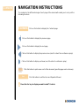
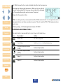
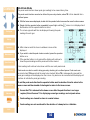
NAVIGATION INSTRUCTIONS
The symbols in the left-hand margin of each page of the manual will enable you to carry out the
following functions:
Click on this button to display the Contents page.
Click on this button to display the previous page.
Click on this button to display the next page.
Click on this button to display the previous view (use it to return from a reference jump).
Click on this button to display next view (use it to return to a reference jump).
Click this button to print some or all of the document (specic pages can be chosen).
Exit
Click this button to exit the User and Operator Manual.
!
Press the Esc key to display normal Acrobat
©
Controls.
Contents
Contents

3
CONTENTS
PROLOGUE .............................................6
T4 Overview ....................................................6
Safety Information ........................................7
Unpacking .............................................10
1. Set-up ..............................................12
1.1 Prior to use .................................................12
1.2 T4 orientation ...............................................12
1.3 Charging & battery indications ................................13
1.4 Fitting the calibration/bump test plate ..........................15
1.5 Fitting the external lter plate .................................16
1.6 +ve Safety™ ................................................17
1.7 Quick view .................................................18
2. Operation ...........................................21
2.1 Turning on .................................................21
2.2 Home screen ...............................................24
2.3 Alarms. . . . . . . . . . . . . . . . . . . . . . . . . . . . . . . . . . . . . . . . . . . . . . . . . . . . .25
2.3.1 Low battery alarm .......................................25
2.3.2 Instantaneous alarm .....................................25
2.3.3 Short term exposure limit alarm (STEL) .....................26
2.3.4 Time weighted average alarm (TWA) ........................26
2.3.5 TWA Resume function* ...................................26
2.4 Alarm and status icons .......................................27
2.5 Accepting and Clearing Alarms ................................28
Exit

4
2.6 Sensors ...................................................29
2.6.1 Oxygen sensor .........................................29
2.6.2 Electro-chemical sensors ................................29
2.6.3 Pellistor sensors .......................................30
2.6.4 Pellistor saver mode ....................................30
2.7 T4 menu icons ..............................................31
2.8 Accessing T4 menu functions .................................32
2.8.1 Home screen ...........................................32
2.8.2 Information Screen ......................................32
2.8.3 Manual zero ............................................33
2.8.4 Peak Mode .............................................34
2.8.5 Bump Test .............................................35
2.8.6 Calibration .............................................37
2.8.7 STEL (Short term exposure limit) ..........................39
2.8.8 TWA (Time weighted average) .............................39
2.8.9 Shutdown .............................................39
2.9 Data Logging ...............................................40
2.10 Event logging ..............................................40
2.11 Bump Test ................................................41
2.12 Calibration ................................................42
2.13 New sensor calibration/service ...............................42
2.14 T4 Aspirator Plate ..........................................43
3. Service and maintenance ..............................45
4. Specication .........................................46
Exit

5
5. Accessories .........................................47
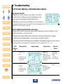
6. Troubleshooting ......................................48
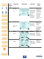
6.1 T4 Fault / Warning / Information Descriptions ....................48
6.1.1 Service Faults ..........................................48
6.1.2 Fault/Warning/Information Messages .......................48
7. Appendices ..........................................55
7.1 Sensor Limitations ..........................................55
7.2 Crowcon contacts ...........................................56
Warranty ...............................................57
Exit

6
PROLOGUE
T4 Overview
Thank you for purchasing T4. At Crowcon we recognise the need for reliable and robust personal
monitors which are sized to be worn and simple to use.
T4 is a portable monitor capable of detecting up to 4 gases in a compact and wearable design. Focused
on users and eet managers alike, T4 offers application focused solutions giving greater operating time
and reduced set up time.
T4 is classied for use in hazardous areas and gives loud and bright audible and visual alarm indications
as well as a vibrate alert. The front mount display is backlit for ease of use, and the simple single button
solution makes using and training quick and easy.
Contents
Exit
Prologue
Operation
Maintenance
Specication
Accessories
Troubleshooting
Appendices
Warranty
Set-up

7
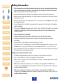
Safety Information
• T4 is a hazardous area certied gas detector and as such must be operated and maintained in
strict accordance with the instructions, warnings and label information included in this manual.
T4 must be operated within the limitations stated.
• Read and understand all instructions in the operation section of this manual prior to use.
• Before use ensure that the equipment is in good condition, the enclosure is intact has not been
damaged in any way.
• If there is any damage to the equipment do not use, contact your local Crowcon ofce or agent
for repair/replacement.
• Do not disassemble or substitute components as this may impair intrinsic safety and invalidate
safety certication.
• Only genuine Crowcon replacement parts must be used; substitute components may invalidate
certication and warranty of the T4 and accessories, reference “Service and Maintenance”
section for details.
• No live maintenance is permissible.
• Observe all warnings and instructions marked on the unit and within this manual.
• Observe site health and safety procedures for gases being monitored and evacuation
procedures.
• Understand the screen display and alarm warnings prior to use.
• If this product is not working properly, read the troubleshooting guide and/or contact your local
Crowcon ofce or agent, for details reference the ‘Crowcon Contacts’ section of the manual
• Ensure maintenance, service and calibration is carried out in accordance with the procedures in
the manual and only by trained personnel.
Charging & Communication (Um = 9.1V)
• The T4 re-chargeable battery must only be charged in non-hazardous (safe) areas.
• Only connect to T4 in a safe area for charging or communications.
• T4 must not be charged or have communication to the device, at ambient temperatures outside
the range 0°C to +40°C.
• T4 has been certied and marked Um = 9.1V therefore, if charging T4 via the T4 Charger
Cradle use only Crowcon supplied AC Adaptor. Otherwise this may impair intrinsic safety and
invalidate safety certication.
• T4 has been certied and marked Um = 9.1V therefore, if charging T4 via the T4 10 way
charger use only Crowcon supplied AC Adaptor. Otherwise this may impair intrinsic safety and
invalidate safety certication.
Contents
Exit
Prologue
Operation
Maintenance
Specication
Accessories
Troubleshooting
Appendices
Warranty
Set-up

8
• Alternative charging and communication cable assemblies types “power cable”, “communication
cable”, “power and communication cable”, “vehicle power cable”, ”cradle power and
communications” and “cradle charger“ are suitable for use with T4.
• Refer to Power & Communication Cables Technical Data” manual (M07996) for further details.
• These devices are intended for use in normal atmospheric conditions of temperature –20 °C
to +55 °C; pressure 80 kPa (0,8 bar) to 110 kPa (1,1 bar); and air with normal oxygen content,
typically 21 % v/v (volume/volume).
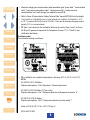
• T4 ‘Type 2’ (as indicated on the certication label) may be used in Zones 1 and 2, for Group
llA, llB and llC gases and vapours and for Temperature Classes T1, T2, T3 and T4. (see
Certication label below).
Certication label
The certication marking is as follows:
• T4 is certied for use in ambient temperatures in the range -20°C to +55°C (-4 to 131°F).
IECEx
IEC 60079-0: 2013, 6th Edition
Explosive atmospheres – Part 0: Equipment - General requirements
IEC 60079-1:2014 7th Edition (T4 Type 2 only)
Explosive atmospheres – Part 1: Equipment protection by ameproof enclosures “d”
IEC 60079-11:2014 6th Edition
Explosive atmospheres - Part 11: Equipment protection by intrinsic safety “i”
Ex db ia IIC T4 Gb -20°C ≤ Ta ≤ +55°C (T4 Type 2)
IECEx ULD 15.0002
0038/
Contents
Exit
Prologue
Operation
Maintenance
Specication
Accessories
Troubleshooting
Appendices
Warranty
Set-up

9
ATEX
EN 60079-0: 2012 + A11:2013
Explosive atmospheres – Part 0: Equipment - General requirements
EN 60079-1:2014 (T4 Type 2 only)
Explosive atmospheres – Part 1: Equipment protection by ameproof enclosures “d”
EN 60079-11:2012
Explosive atmospheres - Part 11: Equipment protection by intrinsic safety “i”
II 2 G Ex db ia IIC T4 Gb -20°C ≤ Ta ≤ +55°C (T4 Type 2)
DEMKO 15 ATEX 1411
UL
Gas detector use in hazardous locations Class 1 Division 1, Groups A, B, C and D only as to
intrinsic safety.
UL 913 Applicable Edition of the UL standard
UL 60079-0:2013 Applicable Edition of the UL standard
UL 60079-11:2013 Applicable Edition of the UL standard
Contents
Exit
Prologue
Operation
Maintenance
Specication
Accessories
Troubleshooting
Appendices
Warranty
Set-up

10
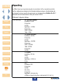
Unpacking
Your T4 will have been inspected and quality checked before it left our manufacturing facility.
It will be congured as a standard unit with standard settings as shown in the table below and
any changes to suit your specic site requirements can be made utilising Portables Pro 2.0 PC
Application and the Communications Cable, part number CH0103.
T4 Standard Conguration Settings:
Alarm levels/type* H
2
S (Hydrogen Sulphide)
Low Alarm = 5 PPM
Rising alarm
Latched
High Alarm = 10 PPM
Rising alarm
STEL = 10 PPM
TWA = 5 PPM
CO (Carbon Monoxide)
Low Alarm = 30 PPM
Rising alarm
Latched
High Alarm = 100 PPM
Rising alarm
STEL = 100 PPM
TWA = 30 PPM
Rising alarm
Latched
O
2
(Oxygen)
Low Alarm = 19% Vol
Falling
Latched
High Alarm = 23.5% Vol
Rising
LEL
Low Alarm = 20%
Rising alarm
Latched
LEL (CH4)
Rising alarm
High Alarm = 40% LEL (CH
4
)
(all T4s are shipped having been calibrated with 2.2% Vol CH
4
)
Contents
Exit
Prologue
Operation
Maintenance
Specication
Accessories
Troubleshooting
Appendices
Warranty
Set-up

11
Calibration Interval 180 days
Bump Test Disabled
Bump Interval 180 days
+ve Safety™ Enabled
Autozero Autozero Conrm
Lock on calibration due Disabled
Lock on bump due Disabled
Home Screen Flipped Disabled
* Other regional defaults are available
Box contents
• T4 checked and calibrated
• Quick start guide
• Calibration/Bump test plate for gas testing T4 – tubing can be bought separately in 1 m (3 feet
lengths)
• Calibration report
• Declaration of Conformity
The following items are optional:
Optional items
• T4 cradle charger – part number T4-CRD
• T4 ten way charger – part number T4-TWC
• T4 sensor lter plate – part number T4-EXT-F
• T4 Aspirator Plate – part number T4-ASP-CAP
• Portables Pro 2.0 software
• Communications cable – part number CH0103
• T4 Vehicle charger – part number T4-VHL (ATEX/IECEx/UL Version)
T4-VHL-BR (INMETRO Version)
• T4 I-Test – part number – IT-T4-11Z-ZB-1 (ATEX Version)
IT-T4-11Z-ZB-2 (UL Version)
IT-T4-11Z-ZB-3 (INMETRO Version)
Contents
Exit
Prologue
Operation
Maintenance
Specication
Accessories
Troubleshooting
Appendices
Warranty
Set-up

12
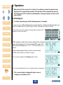
1. Set-up
1.1 Prior to use
Before use, T4 should always be checked for any signs of physical damage.
T4 uses a Lithium Ion (Li-ion) battery pack and should arrive with sufcient charge to be used
straight out the box. However, if this is the rst time of use, the battery will require charging to attain
the full operating time (see Charging & battery indications on page 13).
For battery run times, see the table on page 46.
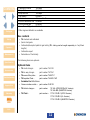
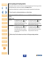
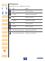
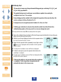
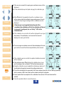
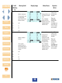
1.2 T4 orientation
Figure 1: T4
À D-ring à Sounder Æ Sensor apertures É Serial Number Label
Á Visual & audible alarms Ä Operator button Ç Alligator clip
 +ve Safety™ indicator Å LCD display È Certication label
À
Ã
È
Ç
Ä
Â
Å
Æ
Á
É
Contents
Exit
Prologue
Operation
Maintenance
Specication
Accessories
Troubleshooting
Appendices
Warranty
Set-up

13
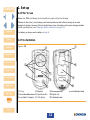
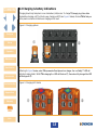
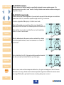
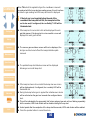
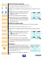
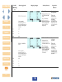
1.3 Charging & battery indications
Charging should only take place in non-hazardous (safe) areas. To charge T4, simply plug it into either
the desktop charging unit À or the ten-way charging unit Á (see Figure 2 below). Ensure T4 ts rmly on
to the power connector of whichever charging unit is used.
Figure 2: Charging options
Referring to Figure 3 below, when T4 is powered off and placed in a charger, the +ve Safety™ LED will
indicate charging status. Whilst T4 is charging the LED will ash red
À, then when fully charged the LED
will ash green Á.
Figure 3: Charging LED status
À
Á
À Á
Contents
Exit
Prologue
Operation
Maintenance
Specication
Accessories
Troubleshooting
Appendices
Warranty
Set-up

14
T4 battery icon contains a maximum of 3 segments and will indicate charging by sequentially
lling the battery segments and repeating this process. When fully charged all three segments
will be displayed.
When T4 is powered up and placed in a charger, the battery icon will indicate charging status but the
+ve Safety™ LED will indicate +ve Safety™ status, NOT charging status.
If T4 is switched on whilst charging, after approximately 30 minutes of being on charge T4 will
automatically power down and continue charging, showing the battery charging icon in the bottom
right of the screen.
Whilst T4 is not charging the battery icon segments, indicate the battery’s state of charge. These are
only shown when T4 is not placed in a charger.
When fully charged and all three segments are shown
À, the battery typically has a maximum of 18
hours run time* (see Figure 4 below). When T4 changes from three to two segments Á the battery
typically has a maximum of 12 hours run time. When T4 changes from two segments to one, the
battery typically has a maximum of 8 hours run time Â. When the battery icon is ashing with no
segments à the battery typically has a maximum of 30 minutes run time before the battery will be
depleted.
Figure 4: Battery Charge Status
i
Should T4 be deep discharged, the charging indication will not be shown until T4 has
been charging for 1 hour and the operator button has been pressed.
Store the battery in a fully charged state and recharge at least once every 6 months.
* Note: A T4 with no ammable sensor tted typically has a maximum run time of 50hrs. The run time between segment
changes will be longer than described above but when the battery icon is ashing with no segments the battery
typically has a maximum of 30 minutes run time before the battery will be depleted.
À Á ÃÂ
Contents
Exit
Prologue
Operation
Maintenance
Specication
Accessories
Troubleshooting
Appendices
Warranty
Set-up

15
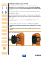
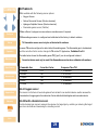
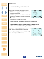
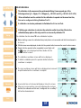
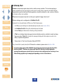
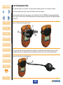
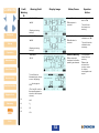
1.4 Fitting the calibration/bump test plate
T4 is supplied with a calibration/bump test plate that can be used to carry out a daily bump test or a
regular calibration. Place the cap into the groove on the left hand side of the T4 rst À, ensuring the at
part of the cap faces the bottom of the T4 and the text is the correct way up, then click the right hand side
in place Á.
Refer to sections 2.8.5 and 2.8.6 for instructions on how bump test and calibrate utilising the calibration/
bump test plate via the T4 menu.
Please note that automated bump testing and calibration of T4 is also possible via the dedicated T4
I-Test bump and calibration station. Please refer to manual M070002 I-Test User & Operator Manual
for further details.
Bump testing and calibration can also be undertaken utilising the Portables Pro 2.0 software and the
calibration/bump test plate.
i
Once the gas test is complete, be sure to remove the calibration/bump test plate for
general use as this will prevent gas reaching the sensors and may prevent T4 responding
to gas.
i
The calibration/bump test plate must not be used in a hazardous area and is for safe area
use only.
Figure 5: Fitting the calibration/bump test plate
À
Á
Contents
Exit
Prologue
Operation
Maintenance
Specication
Accessories
Troubleshooting
Appendices
Warranty
Set-up

16
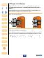
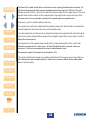
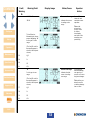
1.5 Fitting the external lter plate
The external lter plate is an optional accessory incorporating lters that allow gas to pass through
but protect the sensors from dirt and debris. The lter plate will protect the sensors making it easier to
maintain T4.
Place the lter plate into the groove on the left hand side of the T4 rst
À, ensuring the at part of the
plate faces the bottom of the T4, then click the right hand side in place Á.
Figure 6: Fitting the external lter plate
The lter plate is suitable for use in a hazardous area.
The lter plate has been designed to operate with the charging accessories and does not need to be
removed when inserting T4 in to the desktop charger, the ten-way charger or the T4 vehicle charger.
i
The lter plate should be replaced if the lters are damaged by substances that could
affect the ow of gas to the sensors, like paints, grease or oils.
À
Á
Contents
Exit
Prologue
Operation
Maintenance
Specication
Accessories
Troubleshooting
Appendices
Warranty
Set-up

17
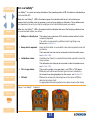
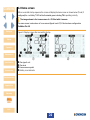
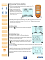
1.6 +ve Safety™
+ve Safety™ is a quick and easy indication of the operating status of T4, this status is indicated by a
front mounted LED.
When the +ve Safety™ LED is illuminated green, this indicates that the unit is functioning as
required and no further action is necessary, such as bump testing or calibration. This enables users
and supervisors to easily see that the employee is safe and following work procedures.
When the +ve Safety™ LED is illuminated red this indicates that one of the following situations has
occurred and will require user action:
• Battery is critically low: The battery has a maximum of 30 minutes runtime before it will be
completely depleted.
This will be accompanied by additional alerts signifying a low
battery, see Section 1.3.
• Bump test is required: Bump test has failed or exceeded the due date required to meet site
procedures.
The bump test due date can be reviewed via the information menu,
see Section 2.8.2.
• Calibration is due: Calibration has failed or exceeded the due date required to meet the
site procedure.
The calibration due date can be reviewed via the information menu,
see Section 2.8.2.
• T4 is in gas alarm: This could be a high or low gas alarm, or a STEL or TWA alarm.
T4 display will indicate which alarm type has been activated by
the relevant icon being displayed on the screen, see Section 2.3.
• T4 fault: T4 must be reviewed by trained personnel for repair as T4 has
detected an internal fault.
An appropriate fault warning will also have been shown on the display.
Figure 7: +ve Safety™ indicators
Contents
Exit
Prologue
Operation
Maintenance
Specication
Accessories
Troubleshooting
Appendices
Warranty
Set-up

18
1.7 Quick view
The conguration details of T4 can be reviewed even if T4 is not powered by momentarily pressing the
operator button.
The device will emit an audible blip and the LED’s to the right of the display will ash red once, the
serial number of T4 will then be displayed for 10 seconds, T4 will then turn off.
To review all conguration items the operator button must be pressed to scroll through the available
screens.
The conguration items that may be displayed are as follows:
• Serial number
• Firmware Version
• Congured User
• Sensors congured lower alarm levels (alarm 1)
• Sensors congured upper alarm levels (alarm 2)
• STEL congured alarm levels (if a toxic sensor is tted)
• TWA congured alarm levels (if a toxic sensor tted)
• Calibration Due Date
• Bump Due Date
• Instrument Date and Time
i
The is shown on all screens indicating that quick view is being accessed.
The battery status
is also shown on each screen.
If +ve Safety™ is congured, the +ve Safety™ LED will also illuminate for the duration of the quick
view review, showing the status of the instrument (see Section 1.6)
Contents
Exit
Prologue
Operation
Maintenance
Specication
Accessories
Troubleshooting
Appendices
Warranty
Set-up

19
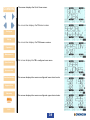
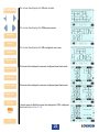
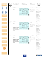
The screen displays the Quick View screen.
The screen then displays the T4 serial number.
The screen then displays the T4 rmware version.
This screen displays the T4’s congured user name.
This screen displays the sensors congured lower alarm levels.
This screen displays the sensors congured upper alarm levels.
Contents
Exit
Prologue
Operation
Maintenance
Specication
Accessories
Troubleshooting
Appendices
Warranty
Set-up

20
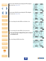
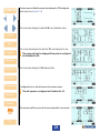
If a toxic sensor is tted this screen displays the STEL congured
alarm levels (see Section 2.3.3).
If a toxic sensor is tted this screen displays the TWA congured
alarm levels (see Section 2.3.4).
This screen displays the date the T4’s next calibration is due.
This screen displays the date the T4’s next bump test is due.
i
This screen will only be displayed if bump test is congured
via Portables Pro 2.0.
This screen displays the T4’s date and time.
Contents
Exit
Prologue
Operation
Maintenance
Specication
Accessories
Troubleshooting
Appendices
Warranty
Set-up
La pagina sta caricando ...
La pagina sta caricando ...
La pagina sta caricando ...
La pagina sta caricando ...
La pagina sta caricando ...
La pagina sta caricando ...
La pagina sta caricando ...
La pagina sta caricando ...
La pagina sta caricando ...
La pagina sta caricando ...
La pagina sta caricando ...
La pagina sta caricando ...
La pagina sta caricando ...
La pagina sta caricando ...
La pagina sta caricando ...
La pagina sta caricando ...
La pagina sta caricando ...
La pagina sta caricando ...
La pagina sta caricando ...
La pagina sta caricando ...
La pagina sta caricando ...
La pagina sta caricando ...
La pagina sta caricando ...
La pagina sta caricando ...
La pagina sta caricando ...
La pagina sta caricando ...
La pagina sta caricando ...
La pagina sta caricando ...
La pagina sta caricando ...
La pagina sta caricando ...
La pagina sta caricando ...
La pagina sta caricando ...
La pagina sta caricando ...
La pagina sta caricando ...
La pagina sta caricando ...
La pagina sta caricando ...
La pagina sta caricando ...
La pagina sta caricando ...
-
 1
1
-
 2
2
-
 3
3
-
 4
4
-
 5
5
-
 6
6
-
 7
7
-
 8
8
-
 9
9
-
 10
10
-
 11
11
-
 12
12
-
 13
13
-
 14
14
-
 15
15
-
 16
16
-
 17
17
-
 18
18
-
 19
19
-
 20
20
-
 21
21
-
 22
22
-
 23
23
-
 24
24
-
 25
25
-
 26
26
-
 27
27
-
 28
28
-
 29
29
-
 30
30
-
 31
31
-
 32
32
-
 33
33
-
 34
34
-
 35
35
-
 36
36
-
 37
37
-
 38
38
-
 39
39
-
 40
40
-
 41
41
-
 42
42
-
 43
43
-
 44
44
-
 45
45
-
 46
46
-
 47
47
-
 48
48
-
 49
49
-
 50
50
-
 51
51
-
 52
52
-
 53
53
-
 54
54
-
 55
55
-
 56
56
-
 57
57
-
 58
58


in altre lingue
- English: Crowcon T4 User manual
Documenti correlati
-
Crowcon Gas-Pro Istruzioni per l'uso
-
-
-
Crowcon T4 Manuale utente
-
-
-
-
-
Altri documenti
-
Monnit MNS2-4-W2-PS Series Guida utente
-
Monnit Alta Long range Wireless Carbon Monoxide Sensor Guida utente
-
Monnit Alta Guida utente
-
CRYSTAL XP2i Istruzioni per l'uso
-
Rosemount X-STREAM Enhanced XECLD Continuous Gas Analyzer Manuale del proprietario
-
-
Casella APEX Personal Sampling Pump Manuale utente
-
RIDGID micro CD-100 Manuale utente
-
Magellan WorldPhone Manuale utente
-
Analog way Ascender 16 Manuale utente