
- ENGLISH
- DEUTSCH
SISTEMA SONORO DI EVACUAZIONE
ELECTROACOUSTIC EMERGENCY WARNING-SYSTEM
INTRODUZIONE / OPERATING INSTRUCTIONS
VDE-0828 / DIN EN-60849 / IEC-60849

EMERGENCY WARNING-SYSTEM
2
Electromagnetic compatibility and low-voltage guidelines: RCS leaves all devices and products, which are subject to the CE guidelines by certified test laboratories test.
By the fact it is guaranteed that you may sell our devices in Germany and in the European Union domestic market without additional checks.
Elektromagnetische Verträglichkeit und Niederspannungsrichtlinien: RCS läßt alle Geräte und Produkte, die den CE-Richtlinien unterliegen durch zertifizierte Prüflabors
testen. Dadurch ist sichergestellt, dass Sie unsere Geräte in Deutschland und im EU-Binnenmarkt ohne zusätzliche Prüfungen verkaufen dürfen.
ISTRUZIONI DI SICUREZZA
Cortesemente, leggere attentamente le istruzioni di sicu-
rezza prima della messa in opera del ESC- 006 A.
1. Installare l’apparecchiatura secondo le seguente gui-
da di riferimento::
• Installare sempre il dispositivo su una superficie piana ed
uniforme..
• Il dispositivo non dovrebbe essere tenuto in luoghi umidi
o bagnati. E’ raccomandabile tenerlo lontano dall’acqua:
• Evitare il contatto del dispositivo con fonti di calore, quali
radiatori o altri dispositivi che producono il calore.
• Installando l’ ESC – 006 A in un armadio da 19” a rack
fare attenzione nel posizionare l’apparecchio in ubna po-
sizione che abbia adeguata ventilazione.
2. Tenere presente le seguenti informazioni quando col-
legate il dispositivo:
• Collegare l’amplificatore dopo la lettura dei manuali
• Per prevenire la scossa elettrica, non aprire la copertura
superiore.
• Collegare solo a 230V ed a 24 V alimentazione di emer-
genza (DC).
IL CONTROLLO E LA VERIFICA DEL PRODOTTO
Controllare con attenzione l’unità per vedere se ci sono dan-
ni dovuti al trasporto. Ogni prodotto RCS è controllato con
attenzione dalla fabbrica ed è imballato in una scatola spe-
ciale per un trasporto sicuro.
Informare immediatamente il corriere se osservate il
danneggiamento della scatola o del prodotto dovuti al
trasporto.
Reso: Imballate l’unità nella scatola ed attendete il controllo
da parte del corriere.
Informare il Vostro rivenditore del reclamo in attesa del tras-
porto per la sostituzione o riparazione.
INSPECTION AND INVENTORY OF THE PRODUCT
Check unit carefully for damage which may have occurred
during transport. Each RCS product is carefully inspected
at the factory and packed in a special carton for safe
transport.
Notify the freight carrier immediately if you observe any
damage to the shipping carton or product!
Return: Repack the unit in the carton and await inspection
by the carrier’s claim agent. Notify your dealer of the pending
freight claim. Returning your unit for service or repairs.
Should your unit require service, contact your dealer.
SAFETY INSTRUCTION
Please read all safety instructions before operating the
ESC-006 A.
1. Install equipment according to the following
guidelines:
• Install the device always on a flat and even surface.
• The device should not be exposed to damp or wet sur-
roundings. Please keep away from water.
• Please avoid using the device near heat sources, such as
radiators or other devices which produce heat.
• To install the ESC-006A in a 19” rack please note that the
appliance should be situated, that the location or positi-
on does not interfere with an adequate ventilation.
2. Keep in mind the following when connecting the
device:
• Connect the amplifier after reading the manuals.
• To prevent electric shock, do not open top cover.
• Connect only to 230 V and 24 V Emergency power (DC).

ESC-006 A
3
INTRODUZIONE
Nel caso di allarme, il sistema sonoro di evacuazione può
evitare il panico, con l’ausilio di annunci comprensibili dagli
altoparlanti, molto più efficienti nell’evacuazione di un edifi-
cio effettuato con l’utilizzo di una sirena.
Naturalmente, la disponibilità e la sicurezza di tali sistemi
deve essere sempre garantita.
Questo avviene controllando continuamente e completa-
mente il percorso del segnale audio.
Lo standard IEC 60849 definisce i requisiti di tali sistemi.
CARATTERISTICHE DEL ESC-006A
• Configurazione semplice ed automatica organizzata alla
messa a punto dell’installazione.
• Disegno compatto con 2 RU.
• 6 linee altoparlanti selezionabili e regolabili.
• Possibilità di collegare fino a 5 stazioni microfoniche di-
gitali VLM-105 e massimo 2 stazioni microfoniche cont-
rollate dai vigili del fuoco ESM – 100D.
• Possibilità di registrare il testo tramite PC
• Funzione di watchdog integrata con il conteggio errori.
• Visualizzazione chiara dei messaggi di errore sul display
con aggiunta di segnale luminoso e di allarme acustico.
• Verifica e controllo dello stato dell’amplificatore, dei mic-
rofoni di emergenza, dei diffusori e del sistema ausiliario
d’alimentazione di emergenza.
• La voce digitale in memoria, contiene un testo per evacu-
azione e una sirena. In caso di necessità messaggi di av-
viso speciali possono essere programmati singolarmente
dall’installatore.
INTRODUCTION
In the case of an alarm, an electroacoustic emergency war-
ning system may avoid panic by understandable speaker an-
nouncements, which are, contrary to the howling of a siren,
a much more efficient way of initiating the evacuation of a
building.
Naturally, the availability and safety of such systems has to
be guaranteed at all times by monitoring the complete signal
path.
The standard IEC 60849 defines the requirements to such
systems.
FEATURES ESC-006A
• Simple and neatly arranged configuration per automati-
cally installation setup.
• Compact design with 2 RU.
• 6 speaker lines switchable and adjustable.
• It is possible to connect up to 5 digital microphone sta-
tions VLM-105 and maximum 2 monitored Fire brigade
microphone stations ESM-100 D.
• Log recording via PC is possible
• Integrated watchdog with error counter
• Error messages are prompted by display in clear text with
additional signal lights and an acoustic warning signal.
• Monitoring of amplifier, emergency microphones, spea-
kerlines and emergency power supply.
• The monitored digital voice memory contains a text for
evacuation and a siren. If you wish, special warning text
messages can be programmed for you.

EMERGENCY WARNING-SYSTEM
4
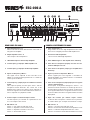
PANNELLO FRONTALE ESC-006 A
1. Display LCD
Display a cristalli liquidi 20 caratteri su due righe informa
costantemente sulla condizione del sistema. Durante la
configurazione i diversi passi d’installazione sono visu-
alizzati nel display. Gli eventuali errori sono indicati dallo
stasse display.
2. Led verde „On“
Indica il funzionamento.
3. Tasto T1 / T2 / inizio (start) / cancellazione (reset)
Tutte le necessarie configurazioni possono essere fatte
dai vari tasti. Particolari più dettagliati per la configurazi-
one possono essere trovati alla pagina _ alla voce “PRO-
CEDURA INSTALLAZIONE”.
4. Led Errore
In caso di errore vi è un segnale ottico ed i led rossi lam-
peggiano. La luce si spegne solo dopo che il guasto vie-
ne eliminato completamente.
5. Comando del volume
I comandi del volume 1 – 6 regolano il livello sonoro della
musica nelle varie zona.
6. Attivazione tasti di comando
La diffusione sonora di sottofondo può essere attivata
(led verde) o disattivata dai pulsanti di comando 1- 6. La
selezione di zona e tutte le chiamate degli ESM-100 D
non sono effettuate dai pulsanti di comando. I VLM-105
e l’ ESM-100D non sono controllati dai pulsanti di cont-
rollo.
FRONT PANEL ESC-006 A
1. LCD Liquid Crystal Display
The clear 20-digit, 2-lines display inform constantly about
the system status.
During the configuration the individual installation steps
are displayed in the text. Arising errors are indicated.
2. Green LED
Operation display „ON“.
3. Button T1, T2, Start and Reset
All necessary configurations can be made by various hot-
keys. More details for the configuration can be found on
page 7 – part “programming”.
4. Error-LED
In the case of an error the red LED flashes an optic signal.
The light expires only, after the complete error has been
eliminated.
5. Volume Controls
The volume controls 1-6 regulate the background music
in the sound level zones.
6. Push button
The background is activated (green LED) or deactivated
by the push buttons 1-6. Zone selection and the ESM-
100 D All call are not effected by the push buttons. The
VLM-105 and the ESM-100 D are not effected.

ESC-006 A
5
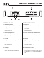
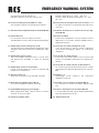
PANNELLO POSTERIORE ESC-006 A
1. Linea altoparlanti 1-6
Prego notare che il cavo degli altoparlanti in linea 100V
deve essere collegato proveniente dall’amplificatore.
2. Uscita linee dell’altoparlante
1-6 un’uscita di 100V dagli altoparlanti.
3. Linea 100V di ingresso dell amplificatore di backup
4. Linea di bassa frequenza (output) di uscita del cavo
audio in 100V per zona 1-6.
5. Linea di bassa frequenza (output) per l’amplificatore
di backup
6. Ingresso per bassa frequenza “Musica”
Questo segnale può essere regolato e controllato sul
frontale del VARES. Per attivare la musica o controllare il
volume, spingere il tasto.
7. Linea a bassa frequenza (output) input per un segnale
esterno supplementare
Questo input ha la priorità sull’ingresso “musica” e la
stazione microfonica VLM-105. Il contatto (8) deve esse-
re ponticellato per attivare questo segnale. Il volume può
essre regolato dall’esterno. Il segnale è trasmesso a tutte
le zone installate ed il volume è regolato tramite il modulo
di playback.
8. Input del contatto per attivare l’input “extern”
La linea di bassa frequenza è attivata via un potenzia-
le contatto libero, per esempio un’interruttore a tempo.
9. DIP switch 1 - 4
Switch 1 = pre chime per VLM-105 on/off
Switch 2 = inserimento / disinserimento impedenza on/off
Switch 3 = tolleranza d’impedenza del 10% o 20%
Switch 4 = inserimento / disinserimento della messa a terra
REAR PANEL ESC-006 A
1. Input Speaker Lines 1-6
Please note that the 100V cable must be connected co-
ming from the amplifier.
2. Output Speaker Lines 1-6
100 V output to the loudspeakers
3. 100 V Cable input for the Backup Amplifier
4. Low Frequency (output)for 100 V Amplifier 1-6
5. Low Frequency (output)for the Backup Amplifier
6. Input Low Frequency “Music”
This signal can be adjusted on the front side of the
VARES. To activate the background music or control the
volume, push the button.
7. Low Frequency (output) Input for additional external
Signal
This input has priority over the input “music” and the
microphone station VLM-105. The contact has to be
bridged for this signal. The volume can be adjusted ex-
ternal. The signal is sent to all installed zones and the vo-
lume is adjusted via a playback module.
8. Contact Input to activate the Input “extern”
The low frequency is activated via a potential free con-
tact, for example a time switch.
9. DIP Switch 1-4
Switch 1 = Pre chime for VLM-105 on/off
Switch 2 = Impedance measurement on/off
Switch 3 = Impedance tolerance 10 or 20 %
Switch 4 = Ground fault on/off

EMERGENCY WARNING-SYSTEM
6
Posizione degli switch: su = OFF giù = ON
Posizione switch di tolleranza impedenza: su = 10%
giù = 20%
10. Connessioni di emergenza microfono da tavolo 1 e 2
La stazione microfonica 1 ha la priorità sulla stazione mi-
crofonica 2
11.Controllo di volume per la stazione microfonica digi-
tale VLM-105
12. Interfaccia RS232
Interfaccia di collegamento al PC per stampare l’elenco
degli errori. E’ necessario il software reperibile nella ho-
mepage del sito RCS.
.
13. Uscita relè di contatto “Emergenza” A+B
I relè di emergenza si attivano durante l’arttivazione
dei microfoni d’emergenza oppure con l’attivazione
dell’allarme.
14. Uscita relè di contatto “Errore”
Il relè errore sarà attivato qualora vi fossa un’errore del
sistema ed e possibile trasformarlo in un segnale di at-
tenzione.
15. Uscita relè di contatto “Guasto di alimentazione”
Se si verifica un guasto di alimentazione questo contatto
sarà attivato fino a quando l’alimentazione non sarà rista-
bilita.
16. Annunci 1 – 4
Monitoraggio circuito d’ingresso per l’attivazione
dell’allarme e del testo.
17. Pannello cieco per l’interfaccia digitale RR-10
Per connettere la stazione microfonica digitale VLM-
105.
18. Ingresso alimentazione di emergenza DC 24V
In caso di utilizzo dell’ ESP-300 A collegare direttamente
la linea di alimentazione 24V DC.
19. Alimentazione 230
Switch position: top=off bottom= on
Impedance tolerance: top=10% bottom= 20%
10. Connection Emergency Desk-Micro 1 and 2
The microphone station 1 has priority before station 2.
11. Volume Control for digital microphone station VLM-105
12. RS-232 Interface
For connection to the PC to print an error list.
You will find the necessary software on the RCS homepage.
13. Output Relay Contact “Emergency” A+B
The equivalent relays tighten during the application of the
emergency desk micro and also if activating the alarm
input.
14. Output Relay Contact „Error“
This contact will be activated if there is a system error,
and therefore the possibility to switch for attention
signal.
15. Output Relay Contact “Power Failure”
If there is a power failure, this contact is switched until
the power is re-established.
16. Announcements 1-4
Monitored circuit input for text and alarm activation.
17. Blank Panel for digital Interface RR-10
(for connection digital microphone VLM-105)
18. Input 24V DC Emergency Power Supply
When using the ESP-300 A – please connect to “unswit-
ched out” on the 24 V output.
19. Input Power Supply 230 V

ESC-006 A
7
PROCEDURA DI INSTALLAZIONE
Per prima cosa attivare la centrale di controllo VARES
ESC-006 A
Tutti i dispositivi e tensioni di funzionamente, che devono
essere controllate dal centro di controllo VARES ESC-006°
dovrebbero essere attivati.
L’attivazione interessa solitamente i seguenti componenti:
• Amplificatore in linea 100V (massimo 6 pezzi)
• Amplificatore di backup
• Stazione dei vigili del fuoco ESM-100D (massimo 2 pezzi)
• Ingresso 1-4 di allarme
• Voltaggio del sistema a 230V AC
• Alimentazione di emergenza 24V DC
Prego prestare attenzione a quanto segue:
I comandi del volume sugli amplificatori collegati devono es-
sere al massimo. La regolazione del volume è fatta dal ESC-
006 A.
Se di fatto durante l’installazione della linea dell’altoparlante
si ha una registrazione con meno di 20 _ sarà misurata.
Questo errore sarà indicato. L’errore deve essere riparato e
l’installazione deve essere nuovamente iniziata.
Se il VLM-105, che non è monitorato è installato in aggiunta,
l’unità RR-10 dell’evacuazione deve essere anch’essa instal-
lata.
Quando, ordinate ESC-006 A e il VLM-105 insieme,
l’interfaccia sarà inserita nella consegna.
INIZIO PROCEDURA DI INSTALLAZIONE
1. Premere “T1” una volta
2. Premere “RESET” tre volte per attivare l’accesso al
sistema
3. 3 Premere “T1” per selezionare system
4. 4 Premere “T2” per iniziare l’installazione
Tutti i componenti sono visualizzati successivamente sul dis-
play. Dopo che l’installazione sarà completata, tutti i compo-
nenti saranno continuamente controllati.
INSTALLATION PROCEDURE
Please activate as a first step the Control Center ESC-
006 A.
All devices and operating voltages, which are to be cont-
rolled by the VARES Control Center ESC-006 A should be
activated.
It usually concerns the following components:
• 100 V amplifier (max. 6 pcs.)
• Backup amplifier
• Fire-Brigade Station (max. 2 pcs.)
• Input alarm message 1-4
• System voltage 230 V AC
• Emergency power 24 V DC
Please note as follows:
The volume controls on the connected amplifiers have to
be adjusted to full volume. The volume regulation is done by
the ESC-006 A.
If done during the installation of the loudspeaker line an ad-
justment with less than 20 � is measured. This error will be
indicated. The error has to be deleted and the installation
must be started again.
If the VLM-105 which is not monitored is installed additional-
ly, the evacuation unit RR-10 has to be installed too. When
ordering both products ESC-006 A and VLM-105 together,
the interface will be assembled in the scope of delivery.
START OF THE INSTALLATION PROCEDURE
1. Push „T1“
2. Push „RESET“ 3 times
to activate the access
3. Push “T1”
To select “System”
4. Push „T2“
the installation starts ...
All components are successively visual on the display. After
the installation is completed, all components will be conti-
nuously checked.

EMERGENCY WARNING-SYSTEM
8
PROGRAMMAZIONE
Soltanto le persone autorizzate dovrebbero program-
mare il sistema. I cambiamenti o gli input falsi possono
compromettere la sicurezza del sistema.
a) REGOLAZIONE VOLUME DEL SEGNALE DI EVACUAZIONE
• Premere T1
• Premere “RESET” tre volte per attivare l’accesso al siste-
ma
• T2 per selezionare il volume
• Con T1 seleziona la chiamata o il testo
• Premere T2 per cambiare lo stato del volume
• T1 = abbassare il volume
• T2 = alzare il volume
• Premere RESET per tornare al menù
La regolazione del volume della musica può essere effet-
tuata dal pannello frontale. Il volume della base microfo-
nica digitale VLM-105 può essere regolato con il potenzi-
ometro “Gain Remote Mic”.
b) MENU’ SPECIALE
b1) Indicatore di Programmazione
• Premere T1
• Premere RESET tre volte per attivare l’accesso al sistema
• Premere T1 per selezionare “system”
• Premere T1 per selezionare “special”
• Premere T1 per selezionare “indicator”
• Premere T1 per selezionare il più appropriato tipo di allarme
Il tipo di allarme dell’annunciatore è indicato attraverso la
scelta di un appropriato messaggio d’emergenza.
• Premere T2
Per comporre il tipo di indicazione, poi premere
START per attivare o disattivare l’indicazione.
• Premere RESET per tornare al menù.
Lo stato di indicazione è:
Input 1 = Messaggio 1
Input 2 = Messaggio 2
Input 3 = Messaggio 3
Input 4 = Messaggio 4
I seguenti messagi sono pre memoirzzati:
Messaggio 1 = messagio di evacuazione
Messaggio 2 = sirena DIN (DIN 33404)
Messaggio 3 = 4 toni chime
Messaggio 4 = 4 toni chime (Westminster)
PROGRAMMING
Only authorized persons should program the system.
Changes or false inputs can affect the security.
a) ADJUSTMENT OF THE EVACUATION SIGNAL VOLUME
• Push T1
• Push RESET 3 times to activate the access
• T2 to select the volume
• With T1 select the text or call station
• Push T2 “to alter”
• T1= to lower the volume
T2= to boost the volume
• Push RESET to prompt menu
The required volume for the background music can be
adjusted on the front side. With “Gain Remote Mic. The
VLM-105 volume can be adjusted.
b) MENU SPECIAL
b1) Indicator Programming
• Push T1
• Push RESET 3 times to activate the access
• Push T1 to select “System”
• Push T1 to select “Special”
• Push T1 to select “Indicator”
• Push T1 to select the appropriate type of alarm
The alarm annunciator inputs are indicated, through
which the appropriate emergency message can be
started.
• Push T2
to dial the indicator and then press
START to activate or deactivate the indicator
• Push RESET to leave the menu
The delivery status for the indicators is:
Input 1 = Message 1
Input 2 = Message 2
Input 3 = Message 3
Input 4 = Message 4
The following signals are deposited:
Message 1 = Evacuation message
Message 2 = DIN siren (DIN 33404)
Message 3 = 4 chime tone
Message 4 = 4 chime tone (Westminster)

ESC-006 A
9
b2) Programmazione segnali pre allarme antecedenti ai
messaggi di evacuazione
• Premere “T1” una volta
• Premere “RESET” tre volte per attivare l’accesso al
sistema
• Premere “T1” per selezionare system
• Premere “T1” per selezionare special
• Premere “T1” per selezionare indicator
• Premere “T1” per selezionare il più appropriato tipo d
allarme
• Premere “T2” per selezionare il segnale di richiamo
• Premere “START” per attivare il segnale
• Premere “RESET” per tornare al menù
Condizioni per il rilascio del segnale
Segnale 1 di richiamo = sirene DIN da 20 secondi
Segnale 2 di richiamo = sirene DIN da 40 secondi
Segnale 3 di richiamo = 2 toni chime
Segnale 4 di richiamo = pre-chime 1 tono
c) PROGRAMMARE L’ANNUNCIO ALLARME 4 COME DIFETTO
IN INGRESSO
L’annuncio d’allarme 4 può essere programmato per
un difetto in ingresso
• Spegnere gli amplificatori
• Spegnere l’ESC-006 A
• Tenere premuto “T1” e accendere (ON) la centrale di
controllo VARES ESC-006 A
• Accendere gli amplificatori
Ora possiamo utilizzare l’ingresso dell’annuncio allarme
per l’analisi degli errori esterni.
I seguenti messaggi di errore compaiono:
l’indicatore request = difetto nel sistema di alimentazione
ausiliaria
l’indicatore disconnection = sovraccarico di sistema
indicatore di short circuit = sistema diffusori
Comunque il messaggio di difetto indicante il sistema di cari-
ca a (contatto di rottura), della linea monitor sistema alimen-
tazione di emergenza (entrambi come contatti normalmente
aperti) può essere registrato simultaneamente.
schema del punto b1): indicatore di ingresso
0V
Melder (indicator) 1-4
VARES
4K7 4K7
b2) Programming of attention signals bevor emergency
massages
• Push T1
• Push RESET 3 times to activate the access
• Push T1 to select “System”
• Push T1 to select “Special”
• Push T1 to select “Indicator”
• Push T1
to select the appropriate type of alarm
• Push T2
to activate the attention signal
• Push „Start“ to activate the Signal
• Push “RESET” to leave the menu
The delivery status for the attention signal
Signal 1 = DIN sirene 20 seconds
Signal 2 = DIN sirene 40 seconds
Signal 3 = 2 tone chime
Signal 4 = pre-chime 1 tone
c) SPECIFICATION ALARM ANNUNCIATOR 4
AS FAULT INPUT.
The alarm annunciator input 4 can be programmed to
fault imput.
• switch of the power amplifier
• switch ESC-006 A without power
• hold T1 and switch the Control Center ESC-006 A
on
• switch on the power amplifier
The alarm annunciatior input can now be used for the
analysis of external errors.
The following error messages appear:
Indicator requested = emergency power system
Indicator disconnection = charge system
Indicator short circuit = speaker network
Therefore fault messages of the charging system (break con-
tact) and of the line monitoring / emergency power system
(both as normally open contacts) can be registered simulta-
neously.
Schematics to point b1): Indicator Input

EMERGENCY WARNING-SYSTEM
10
VARES MENUEMAP
T1
T1
T2
T2
T2
3x
T1
T2
LIVELLO
PROVA
diplay errore
error display
T2
START
selezionare il messaggio
select emergency message
Start
ME S S AGI O 1
ME S S AGI O 2
ME S S AGI O 3
ME S S AGI O 4
T1
T1
T1
T1
T1
S 1
S 2
S 3
S 4
T1
T1
T1
T1
assegnare l‘annunciatore
assign the annunciator
START
attivare l‘annunciatore
activate the annunciator
RESET
rimuovere il menu attivo
exit active menu item
RESET
SISTEMA
T1
T2
SEGNALE
INTERRUTTORE
SPECIALE
inizio dell‘installazione…
installation running…
T2
T1
VOL +VOL –

11
VARES-SYSTEM ACCESSORI
SISTEMA DI ALIMENTAZIONE D’EMERGENZA ESP-
300
Il sistema di alimentazione di emergenza ESP-300 è diseg-
nato perla connessione di oltre 6 amplificatori da 120 watt
come altrettanto di un’amplificatore di backup aggiuntivo.
Gli amplificatori di potenza sono usati con la stessa quantità
ma con capacità più alta.
In entrambe le quantità di ESP-300 A e di accumulatori BA-
080 devono essere raddoppiati. L’amplificatore connesso
con la capacità di 480 watt è connesso con le usicte di sicu-
rezza impostato a 40A. Notare che massimo 2 amplificatore
di backup possono essere usati.
Prego fare attenzione: di fabbrica sono installati fusibili di si-
curezza da 16A sufficiente per amplificatori fino a 240 watt.
Se utilizzate un amplificatore da 480 watt sarà necessario
mettere in sicurezza le uscite con un fusibile da 40A.
L’unità di controllo ESC-006 A è connessa tramite cavo alla
fonte di alimentazione.
Caratteristiche:
• Protezione a bassa carica per la protezione degli accu-
mulatori integrati
• Attivazione automatica della fonte ausiliara
d’alimentazione in caso di mancanza della fonte primaria
d’alimentazione
• 7 x 24V uscita con 16A con fusibili
• Report di rottura dei contatti N/O con un buzzer in man-
canza d’energia, carica o carica sotto il 40% degli accu-
mulatori
• Uso delle batterie interne BA-052 o delle batterie esterne
BA-080
SPECIFICATION ESP-300 A
end of accumulator voltage ca. 27,3 V DC
max. capacitive curren 2,5 A
wattage 105 W
power source 230 V line current
accumulator capacity 27 Ah (BA-052)
42 Ah (BA-080)
Dimensions (WxHxD) 483 x 133 x 350 mm, 3 HE
Weight 11,6 kg
ACCESSORIES
VARES SYSTEM ACCESSORIES
EMERGENCY POWER SUPPLY ESP-300 A
The emergency power supply ESP-300 A is designed for the
connection of up to 6 power amplifiers 120 W as well as
an additional backup amplifier. The power amplifiers stages
of the same quantity but with a higher capacity are used,
both the quantities of ESP-300 A and the quantity of the
accumulators BA-080 must be doubled.
The amplifier with connected capacity of 480 W are
connected to the secured outputs with 40A. Please note that
a maximum of 2 amplifiers per emergency power supply can
be used.
Please note: The output of the ESP-300 A are factory
installed secured with 16 A which is sufficient for an amplifier
up to 240 W. If the amplifier has a capacity of 480 W it is
necessary to secure the outputs with a 40 A (of
delivery)fuse.
The control scope center ESC-006 A is connected via the
“unswitched out” to the emergency power supply.
Features:
• Integrated low charge protection for the protection of the
accumulator
• Automatic activation of the 24V emergency power supply
at power failure with possibility of external activation
• 7x24V output with 16 A separately fused resilient
• Breakdown reporting contact as opener or n/o contact
with buzzer at power failure, charging circuit or capacity
of the accumulator under 40%.
• Use of BA-052 as an internal or BA-080 as external de-
fect accumulator
SPECIFICATION ESP-300 A
end of accumulator voltage ca. 27,3 V DC
max. capacitive curren 2,5 A
wattage 105 W
power source 230 V line current
accumulator capacity 27 Ah (BA-052)
42 Ah (BA-080)
Dimensions (WxHxD) 483 x 133 x 350 mm, 3 HE
Weight 11,6 kg

EMERGENCY WARNING-SYSTEM
12
SYSTEM CONNECTIONS / VERDRAHTUNGSBEISPIEL
AC 230V /50Hz 650W
SERIAL NO.:
400Hz
PROGRAM PRIORITY
leak 10
CONTROL
LEVEL
INPUT INPUT
24V
FUSE
INSIDE
BALANCED OUTPUTS
RMS 240W
W
MONITOR
100V
(42 )(2.6 )
70V
44V
8
COM 25V
P.A POWER AMPLIFIER
MADE IN KOREA
CAUTION
RISK OF ELECTRIC SHOCK
DO NOT OPEN
MODEL NO.: BA-240CP
EQUIPMENT TO RAIN OR MOISTURE.
OR EL ECT RIC S HOC K D ON 'T EXP OS E T HIS
TO REDUCE THE RISK OF FIRE
WARNING:
DC POWER
24V 40A
ON
OFF
4dBu
4dBu
(20 )
MODEL NO.: ESP-300A
6CD-CHANGER
MODEL NO.: R6CD-10
ESC-006A
VARES
Control-Center
R6CD-10
6CD-CHANGER
BA-240CP
Backup-Amp.
BA-240CP
LINE 1-Amp.
LINE 1 Speakers
ESM-100D
VARES
Fire Brigade Call Station
ESP-300A
EMERGENCY
POWER SUPPLY
(Unswitched Out)

13
ACCESSORIES
SISTEMA DI ACCESSORI VARES
STAZIONE DI CHIAMATA DEI VIGILI DEL FUOCO
ESM-100D
La stazione di chiamata ESM-100 D è sempre monitorata in
ottemperanza alle normative VDE0828/EN60849.
Sia la capsula microfonica che il tasto talk per il parlato sono
continuamente controllati e misurati.
Questa operazione viene fatta tramite il control center ESC-
006 A.
La connessione è fatta con cavo a 4 poli schermato:
red = IN+
blue = IN-
white = G (Ground)
yellow = Priority (tasto rilasciato)
SPECIFICATION ESM-100 D
Dynamic microphone Dynamisch
Frequency range 100 – 15000 Hz
Directivity Niere
Impedance 600 Ohm
Selectivity -78dB, +-3dB
Control microphone capsule and talk button with access line
Dimension (WxHxD) 131 x 42 x 181 mm, gooseneck 390 mm
Weight ca. 700 g
STAZIONE MICROFONICA DIGITALE VLM-105
(non monitorata)
La stazione microfonica VLM-105 è abilitata al controllo a
distanza del sistema ESC-006° ed oltre alla possibilità di fare
annunci può controllare 5 zone diverse.
• L’interfaccia digitale RR-10 è all’interno della base e già
disponibile quando viene ordinata insieme al sistema
ESC-006 A ed VLM-105.
• Se il cablaggio è inferiore a 100 mt. Possono essere col-
legate più di 2 stazioni, Se invece il cablaggio è non oltre i
250 mt. Possono essere collegate 3 stazioni al massimo.
• Nella parte posteriore della bese microfonica si può rego-
lare il volume
SPECIFICATION VLM-105
Microphon Electret
Frequency 100-15000 Hz
Directivity Niere
Impedance 1200 Ohm
Selctivity -78dB, +-3dB
Keyboard linie 1–5 und all call
Dimensions (WxHxD) 220 x 53 x 165 mm, gooseneck 290 mm
Weight ca. 1250 g
VARES SYSTEM ACCESSORIES
FIRE BRIGADE CALL STATION ESM-100 D
The fire brigade call station ESM-100 D is monitored compli-
ant to VDE0828/EN60849.
The microphone capsule and the talk button are continuous-
ly for function and via checked measurement reading.
This is evaluated by the control center ESC-006 A.
The connection is made by a 4-pole protected cable.
red = IN+
blue = IN–
white = G (Ground)
yellow = Priority (buttonnreleased)
SPECIFICATION ESM-100 D
Dynamic microphone Dynamisch
Frequency range 100 – 15000 Hz
Directivity Niere
Impedance 600 Ohm
Selectivity -78dB, +-3dB
Control microphone capsule and talk button with access line
Dimension (WxHxD) 131 x 42 x 181 mm, gooseneck 390 mm
Weight ca. 700 g
DIGITAL MICROPHONE STATION VLM-105
(not monitored)
The microphone station VLM-105 enabled the remote cont-
rol of the ESC-006 A and also the language announcements
in up to 5 selectable zones.
• The digital interface RR-10 is contained and with simulta-
neous order ESC-006 A/VLM-105 already pre-mounted
in the scope of supply.
• With a collected administration off 100m can be attached
up to 2 pcs. of the VLM-105. At a collected administrati-
on off 250m maximal 3 pcs.
• On the backside of the microphone station you can
match the volume.
SPECIFICATION VLM-105
Microphon Electret
Frequency 100-15000 Hz
Directivity Niere
Impedance 1200 Ohm
Selctivity -78dB, +-3dB
Keyboard linie 1–5 und all call
Dimensions (WxHxD) 220 x 53 x 165 mm, gooseneck 290 mm
Weight ca. 1250 g

EMERGENCY WARNING-SYSTEM
14
TECHNICAL DATA VARES ESC-006 A
Speaker lines 6 lines, max.480 W each (5 lines with VLM-105)
Fire Brigade call stations 2x ESM-100D suitable for connection
Digital microphone stations up to 5 devices VLM-105 (not monitored)
Signal outputs 7x NF 0dB; transformer balanced;
6 x 100V
Signal inputs 2x NF 0dB; unbalanced (music and external)
7x 100V;
4x supervised switching inputs for text or alarm activation
(Input 4 has a special function to analyse external errors)
Switching outputs 2x „Emergency“ (break or open contact)
1x „Error“ (break or open contact)
1x „Power failure“ (break or open contact)
all max. 120V; max. 2A
PC-interface RS-232
Voice memory Eprom, max. 240 sec.
Display 2-line Display; LEDs
Control panel 4 programming buttons
6 buttons and controller to select the lines an control (only Music)
Power supply 230V AC, 24V DC
Power consumption ~ 25 W / < 26 W
Dimensions (WxHxD), weight 483 x 89 x 340 mm, 2 RU; 6,5 kg

ESC-006 A
15
DATI TECNICI VARES ESC-006 A
Linea altoparlanti 6 linee massino da 480 w ogniuna (5 linee con VLM-105)
Stazione di chiamata vigili del fuoco 2xESM-100D adatti per la connessione
Stazione microfonica digitale più di 5 dispositivi (non monitorati)
Segnale in uscita 7x NF 0db; bilanciate con trasformatore
6 x 100 V
Segnale di ingresso 2x NF 0db; sbilanciate (musica e segnale esterno)
7 x 100 V
4x ingressi sorvegliati per attivazione segnale di allarme
Usicta Switching 2x Emergency (contatti a rottura aperti)
1x Errore (contatti a rottura aperti)
1x Problemi di alimentazione (contatti a rottura aperti)
Tutto massimo 120V; massimo 2
Interfaccia PC RS-232
Memoria messaggi Eprom, massimo 240 secondi
Display 2 linee a Led
Pannello di controllo 4 tasti di programma
6 tasti per selezionare e controllare solo la musica
Alimentazione 230 V AC, 24 V DC
Consumo ~ 25 W / < 26 W
Dimensioni 483 x 89 x 340 mm, 2 RU; 6,5 kg

EMERGENCY WARNING-SYSTEM
© Copyright by RCS AUDIO-SYSTEMS GmbH.
Publication and duplication of the contained data only allowed with our strict permission. Veröffentlichung und Vervielfältigung der enthaltenen Daten, auch auszugsweise, nur mit unserer ausdrücklichen Genehmigung.
Hardware and Software specifications subject to change without notice.
Techische Änderungen in Hardware und Software vorbehalten.
RCS23.07.2007
-
 1
1
-
 2
2
-
 3
3
-
 4
4
-
 5
5
-
 6
6
-
 7
7
-
 8
8
-
 9
9
-
 10
10
-
 11
11
-
 12
12
-
 13
13
-
 14
14
-
 15
15
-
 16
16


RCS ESC-006A Manuale del proprietario
- Tipo
- Manuale del proprietario
- Questo manuale è adatto anche per
in altre lingue
- English: RCS ESC-006A Owner's manual
Altri documenti
-
PROEL PA ZONE8 Manuale utente
-
 Snell & Wilcox TBS100 Manuale utente
-
Lenovo Aptiva 2274 Hardware Maintenance Manual
-
Silvercrest SAB 160 A1 Istruzioni per l'uso
-
MB QUART RAB 1450 Manuale utente
-
-
-
Classé CA-5200 Manuale del proprietario
-
Classé CA-2100 Manuale del proprietario
-
