
TBS100OPS 20/10/06 www.snellwilcox.com Version 2 Issue 5 0.1
TBS100, TBS100D,
TBS100TX, TBS100DTX
Synchronizer/Time Base Correctors
Operator’s
Manual
© October 2006
www.snellwilcox.com
Snell & Wilcox Ltd., Southleigh Park House, Eastleigh Road, Havant, Hants, PO9 2PE, United Kingdom.
For General Enquiry’s contact: Tel: +44 (0) 2392 489000 Fax: +44 (0)23 9245 1411
For Technical assistance contact: Tel: +44 (0) 2392 489058 Fax: +44 (0) 2392 489057
Web: http://www.snellwilcox.com/support Ftp: ftp://ftp.snellwilcox.com/support

TBS100/100D SECTION 0
TBS100OPS 20/10/06 www.snellwilcox.com Version 2 Issue 5 0.2
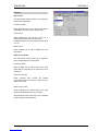
Explanation of Safety Symbols
This symbol refers the user to important information contained in
the accompanying literature. Refer to manual.
This symbol indicates that hazardous voltages are present inside.
No user serviceable parts inside.
This unit should only be serviced by trained personnel.
Servicing instructions where given, are for use by
qualified service personnel only.
To reduce risk of electric shock do not perform any
servicing other than that contained in the operating
instructions unless you are qualified to do so.
Refer all servicing to qualified personnel.
To reduce the risk of electric shock, do not expose this appliance
to rain or moisture.
Always ensure that the unit is properly earthed and power connections
correctly made.
This equipment must be supplied from a power system providing a
PROTECTIVE EARTH connection and having a neutral connection
which can be reliably identified.
The power outlet supplying power to the unit should be close to the
unit and easily accessible
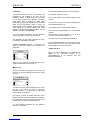
Power connection in countries other than the USA
The equipment is normally shipped with a power cable with a standard IEC
moulded free socket on one end and a standard IEC moulded plug on the other.
If you are required to remove the moulded mains supply plug, dispose of the
plug immediately in a safe manner.
The colour code for the lead is as follows:
GREEN/YELLOW lead connected to E
(Protective Earth Conductor)
BLUE lead connected to N (Neutral Conductor)
BROWN lead connected to L (Live Conductor)
Caution If the unit has two mains supply inputs ensure that both power
cords are plugged into mains outlets operating from the same phase.
L N
E
N L
E
GB
!
CAUTION
RISK OF ELECTRIC SHOCK
DO NOT REMOVE COVERS
NO USER SERVICEABLE PARTS
REFER SERVICING TO QUALIFIED
PERSONNEL ONLY
!
!
Safety Warnings
Légende :
Ce symbole indique qu'il faut prêter attention et se référer
au manuel.
Ce symbole indique qu'il peut y avoir des tensions électriques
à l'intérieur de l'appareil. Ne pas intervenir sans l'agrément
du service qualifié.
Pour réduire le risque de choc électrique, ne pas exposer l'appareil
dans un milieu humide.
Toujours s'assurer que l'unité est correctement alimentée,
en particuliers à la liaison à la terre.
La source électrique de cet équipement doit posséder une connexion
à la terre , ainsi qu'une liaison « neutre » identifiable.
La prise électrique qui alimente l'appareil doit être proche
de celle-ci et accessible.
Câble secteur de pays autres que les Etats-Unis
L'équipement est livré avec un câble secteur au standard IEC, moulé
mâle/femelle.
Si vous souhaitez changr la prise mâle de votre cordon, voici les
codes couleurs des fils :
Le fil VERT/JAUNE est connecté à T (Terre)
Le fil BLEU est connecté à N (Neutre)
Le fil MARRON est connecté à P (Phase)
Attention si l'appareil a 2 alimentations, s'assurer que les cordons
soient branchés sur la même phase.
Précaution d'emploi :
F
Les procédures de maintenance ne concernent
que le service agréé. Afin de réduire le risque de
choc électrique, il est recommandé de se limiter
aux procédures d'utilisation, à moins d'en être qualifié.
Pour toute maintenance, contacter le service compétent.
!
ATTENTION
RISQUE DE CHOC ELECTRIQUE
NE PAS RETIRER LE COUVERCLE
NE PAS INTERVENIR SANS
L'AGREMENT DU SERVICE
QUALIFIE
P N
T
N P
T
Connecteur Prise
!
!
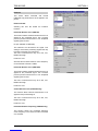
Erklärung der Sicherheitssymbole
Dieses Symbol weist den Benutzer auf wichtige Informationen
hin, die in der begleitenden Dokumentation enthalten sind.
Dieses Symbol zeigt an, dass gefährliche Spannung vorhanden ist.
Es befinden sich keine vom Benutzer zu wartenden Teile im Geräteinneren.
Dieses Gerät sollte nur von geschultem Personal gewartet werden
Um das Risiko eines Elektroschocks zu reduzieren, setzen Sie das
Gerät weder Regen noch Feuchtigkeit aus.
Stellen Sie immer sicher, dass das Gerät ordnungsgemäß geerdet
und verkabelt ist.
Dieses Equipment muss an eine Netzsteckdose mit Schutzleiter
angeschlossen werden und einen zuverlässig identifizierbaren Nullleiter haben.
Die Netzsteckdose sollte nahe beim Gerät und einfach zugänglich sein.
Netzanschluss in anderen Ländern als der USA
Das Equipment wird im Normalfall mit einem Netzkabel mit Standard IEC
Anschlussbuchse und einem Standard IEC Anschlussstecker geliefert.
Sollten Sie den angeschweißten Stecker auswechseln müssen, entsorgen
Sie diesen bitte umgehend. Die farbliche Belegung des Netzkabels ist wie folgt:
GRÜN GELB E = Schutzleiter
BLAU N = Nulleiter
BRAUN L = P = Phase
Achtung: Wenn das Gerät zwei Anschlussbuchsen hat, stellen
Sie bitte sicher, dass beide Netzkabel mit der selben Phase in die
Netzsteckdose gesteckt werden.
Sicherheits-Warnhinweise
D
!
!
Die angeführten Service-/Reparatur-Anweisungen sind
ausschließlich von qualifiziertem Service-Personal
auszuführen. Um das Risiko eines lektroschocks zu
reduzieren, führen Sie ausschließlich die im
Benutzerhandbuch eschriebenen Anweisungen aus,
es sei denn, Sie haben die entsprechende Qualifikation.
Wenden Sie sich in allen Service-Fragen an qualifiziertes Personal.
!
ACHTUNG
Gefahr von Elektroschocks.
Abdeckungen nicht entfernen
Keine vom Benutzer zu wartende Teile
Wenden Sie sich ausschließlich
an qualifiziertes Personal
L =
Phase N =
Nulleiter N =
Nulleiter L =
Phase
E =
Schutzleiter
E =
Schutzleiter
Explicación de los Símbolos de Seguridad
Éste símbolo refiere al usuario información importante contenida
en la literatura incluida. Referirse al manual.
Éste símbolo indica que voltajes peligrosos están presentes en el interior.
No hay elementos accesibles al usuario dentro.
Esta unidad sólo debería ser tratada por personal cualificado.
Las instrucciones de servicio cuando sean dadas, son
sólo para uso de personal cualificado. Para reducir el
riesgo de choque eléctrico no llevar a cabo ninguna
operación de servicio aparte de las contenidas en las
instrucciones de operación, a menos que se esté
cualificado para realizarlas.
Referir todo el trabajo de servicio a personal cualificado.
Para reducir el riesgo de choque eléctrico, no exponer este equipo
a la lluvia o humedad.
Siempre asegurarse de que la unidad está propiamente conectada a
tierra y que las conexiones de alimentación están hechas correctamente.
Este equipo debe ser alimentado desde un sistema de alimentación
con conexión a TIERRA y teniendo una conexión neutra fácilmente
identificable.
La toma de alimentación para la unidad debe ser cercana y fácilmente
accesible.
Conexión de alimentación en otros países que no sean USA
El equipo es normalmente entregado con un cable de alimentación con un
enchufe hembra estándar IEC en un extremo y con una clavija estándar
IEC en el otro. Si se requiere eliminar la clavija para sustituirla por otra,
disponer dicha clavija de una forma segura.
El código de color a emplear es como sigue:
Advertencia Si la unidad tuviera dos tomas de alimentación, asegurarse
de que ambos cables de alimentación están conectados a la misma fase.
ESP
!
!
Advertencias de Seguridad
L N
E
N L
E
Clavija
Aerea Macho Enchufe
Aereo Hembra
VERDE/ AMARILLO conectado a E
(Conductor de protección a Tierra
-Earth en el original-)
AZUL conectado a N (Conductor Neutro -Neutral en el original-)
MARRÓN conectado a L (Conductor Fase -Live en el original-)
RIESGO DE CHOQUE ELECTRICO
NO QUITAR LAS PROTECCIONNES
ELEMENTOS NO ACCESIBLES AL
USUARIO.
SERVICIO SOLAMENTE A PERSONAL
CUALIFICADO

TBS100/100D SECTION 0
TBS100OPS 20/10/06 www.snellwilcox.com Version 2 Issue 5 0.3
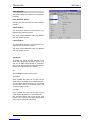
Simboli di sicurezza:
Questo simbolo indica l'informazione importante contenuta nei
manuali appartenenti all'apparecchiatura. Consultare il manuale.
Questo simbolo indica che all'interno dell'apparato sono presenti
tensioni pericolose. Non cercare di smontare l'unità.
Per qualsiasi tipo di intervento rivolgersi al personale qualificato.
Le istruzioni relative alla manutenzione sono ad uso
esclusivo del personale qualificato. E' proibito all'utente
eseguire qualsiasi operazione non esplicitamente
consentita nelle istruzioni. Per qualsiasi informazione
rivolgersi al personale qualificato.
Per prevenire il pericolo di scosse elettriche è necessario non esporre
mai l'apparecchiatura alla pioggia o a qualsiasi tipo di umidità.
Assicurarsi sempre, che l'unità sia propriamente messa a terra e che
le connessioni elettriche siano eseguite correttamente.
Questo dispositivo deve essere collegato ad un impianto elettrico
dotato di un sistema di messa a terra efficace.
La presa di corrente deve essere vicina all'apparecchio
e facilmente accessibile.
Connessione elettrica nei paesi diversi dagli Stati Uniti
L'apparecchiatura normalmente è spedita con cavo pressofuso con la presa
e spina standard IEC. Nel caso della rimozione della spina elettrica,
gettarla via immediatamente osservando tutte le precauzioni del caso.
La leggenda dei cavi è la seguente:
VERDE/GIALLO cavo connesso
ad "E" (terra)
BLU cavo connesso ad "N" (neutro)
MARRONE cavo connesso ad "L" ( fase)
Attenzione! Nel caso in cui l'apparecchio abbia due prese di corrente,
assicurarsi che i cavi non siano collegati a fasi diverse della rete elettrica.
I
!
!
Attenzione:
!
ATTENZIONE
L N
E
N L
E
Presa volante Spina volante
RISCHIO DI SHOCK ELETTRICO
NON CERCARE DI SMONTARE
L'UNITA PER QUALSIASI TIPO DI
INTERVENTO RIVOLGERSI AL
PERSONALE QUALIFICATO
Förklaring av Säkerhetssymboler
Denna symbol hänvisar användaren till viktig information som
återfinns i litteraturen som medföljer. Se manualen.
Denna symbol indikerar att livsfarlig spänning finns på insidan.
Det finns inga servicevänliga delar inne i apparaten.
Denna apparat få endast repareras av utbildad personal.
Serviceinstruktioner som anges avser endast kvalificerad
och utbildad servicepersonal. För att minska risken för
elektrisk stöt, utför ingen annan service än den som
återfinns i medföljande driftinstruktionerna, om du ej är
behörig. Överlåt all service till kvalificerad personal.
För att reducera risken för elektrisk stöt, utsätt inte apparaten för
regn eller fukt.
Se alltid till att apparaten är ordentligt jordad samt att strömtillförseln
är korrekt utförd.
Denna apparat måste bli försörjd från ett strömsystem som är försedd
med jordadanslutning samt ha en neutral anslutning som lätt identifierbar.
Vägguttaget som strömförsörjer apparaten bör finnas i närheten samt
vara lätttillgänglig.
Strömkontakter i länder utanför USA
Apparaten utrustas normalt med en strömkabel med standard IEC gjuten
honkontakt på ena änden samt en standard IEC gjuten hankontakt på den
andra änden. Om man måste avlägsna den gjutna hankontkaten, avyttra
denna kontakt omedelbart på ett säkert sätt. Färgkoden för ledningen är följande:
GRÖN/GUL ledning ansluten till E
(Skyddsjordad ledare)
BLÅ ledning ansluten till N (Neutral ledare)
BRUN ledning ansluten till L (Fas ledare)
Varning! Om enheten har två huvudsakliga elförsörjningar, säkerställ att
båda strömkablarna som är inkopplade i enheten arbetar från samma fas.
S
!
CAUTION
RISK OF ELECTRIC SHOCK
DO NOT REMOVE COVERS
NO USER SERVICEABLE PARTS
REFER SERVICING TO QUALIFIED
PERSONNEL ONLY
!
!
Säkerhetsvarningar
L N
E
N L
E
Stickkontakt-Hane Stickkontakt-Hona
Forklaring på sikkerhedssymboler
Dette symbol gør brugeren opmærksom på vigtig information
i den medfølgende manual.
Dette symbol indikerer farlig spænding inden i apparatet. Ingen bruger
servicerbare dele i apparatet på brugerniveau.
Dette apparat må kun serviceres af faglærte personer..
Serviceinstruktioner er kun til brug for faglærte
servicefolk. For at reducere risikoen for elektrisk
stød må bruger kun udføre anvisninger i
betjeningsmanualen.
Al service skal udføres af faglærte personer.
For at reducere risikoen for elektrisk stød må apparatet ikke
udsættes for regn eller fugt.
Sørg altid for at apparatet er korrekt tilsluttet og jordet.
Dette apparat skal forbindes til en nettilslutning, der yder
BESKYTTENDE JORD og 0 forbindelse skal være tydeligt markeret.
Stikkontakten, som forsyner apparatet, skal være tæt på apparatet
og let tilgængelig
.
Nettilslutning i andre lande end USA
Udstyret leveres normalt med et strømkabel med et standard IEC støbt løst
hunstik i den ene ende og et standard IEC støbt hanstik i den anden ende.
Hvis et af de støbte stik på strømkablet er defekt, skal det straks kasseres på
forsvarlig vis. Farvekoden for lederen er som følger:
GRØN/GUL leder forbundet til J (Jord)
BLÅ leder forbundet til 0
BRUN leder forbundet til F(Fase)
Forsigtig Hvis enheden har to lysnetindgange, skal der sørges for at
begge ledninger tilsluttes lystnetudgange fra den samme fase.
DK
!
!
!
Sikkerhedsadvarsler
!
FORSIGTIG
RISIKO FOR ELEKTRISK STØD
DÆKPLADER MÅ IKKE FJERNES
INGEN BRUGER SERVICERBARE
DELE SERVICE MÅ KUN UDFØRES
AF FAGLÆRTE PERSONER
F 0
J
0 F
J
Han-stik Hun-stik
Turvamerkkien selitys
Tämä merkki tarkoittaa, että laitteen mukana toimitettu kirjallinen
materiaali sisältää tärkeitä tietoja. Lue käyttöohje.
Tämä merkki ilmoittaa, että laitteen sisällä on vaarallisen voimakas jännite.
Sisäpuolella ei ole mitään osia, joita käyttäjä voisi itse huoltaa.
Huollon saa suorittaa vain alan ammattilainen.
Huolto-ohjeet on tarkoitettu ainoastaan alan
ammattilaisille. Älä suorita laitteelle muita
toimenpiteitä, kuin mitä käyttöohjeissa on
neuvottu, ellet ole asiantuntija. Voit saada sähköiskun.
Jätä kaikki huoltotoimet ammattilaiselle.
Sähköiskujen välttämiseksi suojaa laite sateelta ja kosteudelta.
Varmistu, että laite on asianmukaisesti maadoitettu ja että
sähkökytkennät on tehty oikein.
Laitteelle tehoa syöttävässä järjestelmässä tulee olla
SUOJAMAALIITÄNTÄ ja nollaliitännän on oltava luotettavasti
tunnistettavissa.
Sähköpistorasian tulee olla laitteen lähellä ja helposti tavoitettavissa.
Sähkökytkentä
Laitteen vakiovarusteena on sähköjohto, jonka toisessa päässä on muottiin
valettu, IEC-standardin mukainen liitäntärasia ja toisessa päässä muottiin
valettu, IEC-standardin mukainen pistoliitin. Jos pistoliitin tarvitsee poistaa,
se tulee hävittää heti turvallisella tavalla. Johtimet kytketään seuraavasti:
KELTA-VIHREÄ suojamaajohdin E-napaan
SININEN nollajohdin N-napaan
RUSKEA vaihejohdin L-napaan
Huom! Jos laitteessa on kaksi verkkojännitteen tuloliitäntää, niiden johdot
on liitettävä verkkopistorasioihin, joissa on sama vaiheistus.
FI
!
!
Turvaohjeita
!
SÄHKÖISKUN VAARA ÄLÄ AVAA
LAITTEEN KANSIA EI SISÄLLÄ
KÄYTTÄJÄLLE HUOLLETTAVIA
OSIA HUOLTO AINOASTAAN
AMMATTILAISEN SUORITTAMANA
VAROITUS
L N
E
N L
E
Pistoliitin Liitäntärasia

TBS100/100D SECTION 0
TBS100OPS 20/10/06 www.snellwilcox.com Version 2 Issue 5 0.4
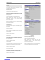
Símbolos de Segurança
O símbolo triangular adverte para a necessidade de consultar o
manual antes de utilizar o equipamento ou efectuar qualquer ajuste.
Este símbolo indica a presença de voltagens perigosas no interior
do equipamento. As peças ou partes existentes no interior do equipamento
não necessitam de intervenção, manutenção ou manuseamento por parte
do utilizador. Reparações ou outras intervenções devem ser efectuadas
apenas por técnicos devidamente habilitados.
As instruções de manutenção fornecidas são para
utilização de técnicos qualificados. Para reduzir o
risco de choque eléctrico, não devem ser realizadas
intervenções no equipamento não especificadas no
manual de instalações a menos que seja efectuadas
por técnicos habilitados.
Para reduzir o risco de choque eléctrico, não expor este equipamento
à chuva ou humidade.
Assegurar que a unidade está sempre devidamente ligada à terra e
que as ligações à alimentação estão correctas.
O sistema de alimentação do equipamento deve, por razões de
segurança, possuir ligação a terra de protecção e ligação ao
NEUTRO devidamente identificada.
A tomada de energia à qual a unidade está ligada deve situar-se na
sua proximidade e facilmente acessível.
Ligação da alimentação noutros países que não os EUA
O equipamento é, normalmente, enviado com cabo de alimentação com ficha
IEC fêmea standard num extremo e uma ficha IEC macho standard no extremo
oposto. Se for necessário substituir ou alterar alguma destas fichas, deverá
remove-la e elimina-la imediatamente de maneira segura.
O código de cor para os condutores é o seguinte:
Condutor VERDE/AMARELO ligado a E (Terra)
Condutor AZUL ligado a N (Neutro)
Condutor CASTANHO ligado a L (Vivo).
Atenção: Se a unidade tem duas fontes de alimentação assegurar que os
dois cabos de alimentação estão ligados a tomadas pertencentes à mesma fase.
P
!
!
Avisos de Segurança
L N
E
N L
E
Ficha Livre Tomada Livre
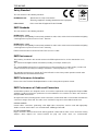
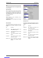
Products employing Lithium batteries
Power cable supplied for the USA
The equipment is shipped with a power cord with a standard IEC molded free socket on one end and a
standard 3-pin plug on the other. If you are required to remove the molded mains supply plug, dispose of the
plug immediately in a safe manner. The color code for the cord is as follows:
GREEN lead connected to E (Protective Earth
Conductor)
BLACK lead connected to L (Live Conductor)
WHITE lead connected to N (Neutral Conductor)
For products with more than one power supply inlet
Caution:
To reduce the risk of electric shock plug each power supply cord into separate branch circuits
employing separate service grounds.
G
CAUTION
This equipment contains a lithium battery.
There is a danger of explosion if this is replaced incorrectly.
Replace only with the same or equivalent type.
Dispose of used batteries according to the instructions of the manufacturer.
Batteries shall only be replaced by trained service technicians.

TBS100/100D SECTION 0
TBS100OPS 20/10/06 www.snellwilcox.com Version 2 Issue 5 0.5
Rack Mounting the Enclosure
When rack-mounting the product, one of the following methods of installation must be used: -
• Place the unit on a suitably specified, and installed rack shelf and secure the product to the rack via the
front rack ears or,
• Fit the unit using the rear rack mount kit available from Snell & Wilcox by quoting the order code FGACK
RACK-MNT-KIT.
This product must not be rack mounted using only the front rack ears.

TBS100/100D SECTION 0
TBS100OPS 20/10/06 www.snellwilcox.com Version 2 Issue 5 0.6
Safety Standard
This unit conforms to the following standards:
BS EN60950:1992 Specification for safety of information
technology equipment, including electrical business equipment
cULus Listed Professional Video Equipment File No. E193966
EMC Standards
This unit conforms to the following standards:
BS EN 55103-1 : 1997
Electromagnetic Compatibility, Product family standard for audio, video, audio-visual and entertainment lighting
control apparatus for professional use. Part 1. Emission
BS EN 55103-2 : 1997
Electromagnetic Compatibility, Product family standard for audio, video, audio-visual and entertainment lighting
control apparatus for professional use. Part 2. Immunity
Federal Communications Commission Rules Part 15, Class A :1998
EMC Environment
The product(s) described in this manual conform to the EMC requirements for, and are intended for use in,
either
The commercial and light industrial environment (including, for example, theatres) E2
or
The controlled EMC environment (for example purpose-built broadcasting or recording studios), and the rural
outdoor environment (far away from railways, transmitters, overhead power lines, etc.) E4
The applicable environment is stated in the Technical Profile section of the product operation manual under
“EMC Performance Information/Environment.”
EMC Performance Information
Please refer to the Technical Profile/Specifications section of the product operation manual.
EMC Performance of Cables and Connectors
Snell & Wilcox products are designed to meet or exceed the requirements of the appropriate European EMC
standards. In order to achieve this performance in real installations it is essential to use cables and connectors
with good EMC characteristics.
All signal connections (including remote control connections) shall be made with screened cables terminated in
connectors having a metal shell. The cable screen shall have a large-area contact with the metal shell.
COAXIAL CABLES
Coaxial cables connections (particularly serial digital video connections) shall be made with high-quality
double-screened coaxial cables such as Belden 8281 or BBC type PSF1/2M.
D-TYPE CONNECTORS
D-type connectors shall have metal shells making good RF contact with the cable screen. Connectors having
"dimples" which improve the contact between the plug and socket shells, are recommended.
No: 60AA
Professional Video
Equipment

TBS100/100D SECTION 0
TBS100OPS 20/10/06 www.snellwilcox.com Version 2 Issue 5 0.7
About this Manual
This manual covers the following products:
• TBS100 Synchronizer/Time Base Corrector
• TBS100D Synchronizer/Time Base Corrector
• TBS100TX Synchronizer/Time Base Corrector
• TBS100DTX Synchronizer/Time Base Corrector
Packing List
The unit is supplied in a dedicated packing carton provided by the manufacturer and should not be accepted if
delivered in inferior or unauthorised materials. Carefully unpack the carton and check for any shipping damage
or shortages.
Any shortages or damage should be reported to the supplier immediately.
Enclosures:
• 1U Mainframe fitted with TBS100 card(s)
• Power cable
• Operator's Manual
Software Version Amendments
Notes about Versions Fitted
Firmware. This TBS100 is shipped with Version 5.1.5 of the firmware.
This TBS100D is shipped with Version 6.0.6 of the firmware.
Manufacturers Notice
Copyright protection claimed includes all forms and matters of copyrightable material and information now
allowed by statutory or judicial law or hereinafter granted, including without limitation, material generated from
the software programs which are displayed on the screen such as icons, screen display looks etc.
Reproduction or disassembly of embedded computer programs or algorithms prohibited.
Copyrighted names: Microsoft Windows™
Information in this manual and software are subject to change without notice and does not represent a
commitment on the part of Snell & Wilcox Ltd. The software described in this manual is furnished under a
licence agreement and may not be reproduced or copied in any manner without prior agreement with Snell &
Wilcox Ltd. or their authorised agents.

TBS100/100D SECTION 0
TBS100OPS 20/10/06 www.snellwilcox.com Version 2 Issue 5 0.8
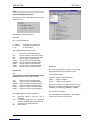
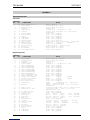
Table of Contents
SECTION
1 Introduction
Description.......................................................................................................................... 1.1
Features ............................................................................................................................. 1.2
2 Specifications ................................................................................................................... 2.1
3 Installation
Power Connections .................................................................................................. 3.1
Input Connections .................................................................................................... 3.2
Output Connections ................................................................................................. 3.3
Communication Connections.................................................................................. 3.3
Opening and Closing the Front Panel..................................................................... 3.4
Matching the Front Panel to a Gateway Address .................................................. 3.4
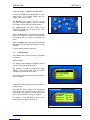
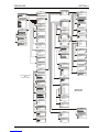
4 Operation
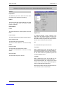
Operating the TBS100 using the Front Panel Buttons and the Menu System................... 1
Using the Dedicated Push Buttons......................................................................... 4.4
Input.................................................................................................................. 4.4
Input select........................................................................................................ 4.4
Timing............................................................................................................... 4.6
Freeze............................................................................................................... 4.6
Pattern .............................................................................................................. 4.6
Noise reduce..................................................................................................... 4.7
Y gain (luminance gain) .................................................................................... 4.8
C gain (chrominance gain)................................................................................ 4.8
Black ................................................................................................................. 4.8
Hue ................................................................................................................... 4.8
Memory 1, 2, 3.................................................................................................. 4.9
Genlock........................................................................................................... 4.10
Enhance.......................................................................................................... 4.11
Setup............................................................................................................... 4.12
Browse............................................................................................................ 4.16
Status.............................................................................................................. 4.17

TBS100/100D SECTION 0
TBS100OPS 20/10/06 www.snellwilcox.com Version 2 Issue 5 0.9
4 Operation (continued)
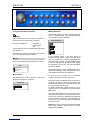
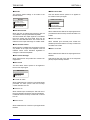
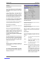
RollCall PC Control Panel Screens for the TBS100/100D/100TX/100DTX...................... 4.19
Control ............................................................................................................ 4.19
Input Select..................................................................................................... 4.19
Standards........................................................................................................ 4.20
Proc Amp ........................................................................................................ 4.21
Features.......................................................................................................... 4.22
Enhancer......................................................................................................... 4.23
Noise Reduction.............................................................................................. 4.24
Encoder........................................................................................................... 4.25
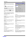
Genlock........................................................................................................... 4.26
Memories ........................................................................................................ 4.28
RollTrack 1-4, RollTrack 5-8........................................................................... 4.29
GPI.................................................................................................................. 4.30
Logging And Preset ........................................................................................ 4.32
Status.............................................................................................................. 4.33
Help................................................................................................................. 4.34
Operation via Card Edge Controls..................................................................................... 4.35
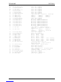
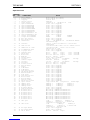
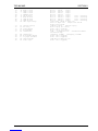
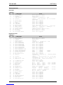
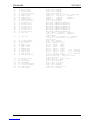
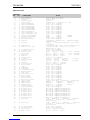
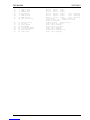
5 Appendix 1 RollCall Commands
TBS100D Commands................................................................................................ 5.1
TBS100 Commands .................................................................................................. 5.5

TBS100/100D SECTION 0
TBS100OPS 20/10/06 www.snellwilcox.com Version 2 Issue 5 0.10
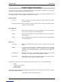
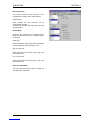
Product Support Procedure
If you experience any technical or operational difficulties with a Snell & Wilcox product please do not hesitate
to contact us or utilize our online form to request assistance.
There is a lot of information you can give us that will enable us to diagnose your problem swiftly. Please read
the following guidelines, as these suggestions will help us to help you.
Basic Information
For Units ..................... Please provide the exact product Model, unit Serial Number and Software
Version information.
For Cards or Modules . Please provide the Sub-Assembly Number, card Serial Number and the
Software Version information.
Basic Application
Inputs .......................... Please provide full details of the Input Signals being used including any
references etc. and where they are being generated.
Outputs ....................... Please provide full details of the Output Signals required and how they are
being monitored.
System ........................ Please provide a brief description of the system in which your S&W equipment
is currently being used.
Basic Tests
Preset Unit .................. Please use the Preset Unit function to return the settings back to the factory
default.
RollCall ........................ Is your unit currently connected to a RollCall capable PC? This software is
obtainable for free and provides a very user friendly GUI for virtually all S&W
equipment - perfect for complex products, large systems or those with passive
front panels.
Card Edge Info. ........... What is the status of the card edge LEDs or display? These can often provide
information such as power status and input detection conditions.
Internal TPG ............... Many S&W products have an internal test pattern/tone generator. Please
activate this to assist you with your problem analysis.
In addition to the above, please do not forget to provide us with all of the necessary contact information:
• Names
• Telephone & Fax numbers
• e-mail addresses
• Business address
A form has been provided for this information and will be found on the next page or an on-line form is available
on the Snell & Wilcox website at:
http://www.snellwilcox.com/support/request

TBS100/100D SECTION 0
TBS100OPS 20/10/06 www.snellwilcox.com Version 2 Issue 5 0.11
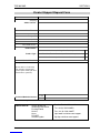
Product Support Request Form
Name: *
Company:
Address Details: *
Post/ZIP Code:
Country: *
Telephone: *
Fax:
Email: *
Local S&W Center: *
Product Name: *
Switchers (i.e. Magic DaVE, Switchpack, Kahuna)
File & Data Transfer Products (i.e. RollCall, Memphis & iCR)
Product Type: *
Video Products (i.e. Modular, Kudos Plus and Alchemist)
Unit Serial Number: *
Fault/Spare Part Information: *
(please advise us how many
units show this fault and the
system layout showing all other
manufacturers' products)
e-mail
* Preferred Method of Contact: Phone
• Item is required.
Please mail to:
Snell & Wilcox Ltd.,
Southleigh Park House,
Eastleigh Road,
Havant,
Hants,
PO9 2PE.
United Kingdom.
Service Contact Information:
Tel: +44 (0) 2392 489058
Fax: +44 (0) 2392 489057
http://www.snellwilcox.com/support
ftp://ftp.snellwilcox.com/support

TBS100/100D SECTION 0
TBS100OPS 20/10/06 www.snellwilcox.com Version 2 Issue 5 0.12
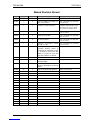
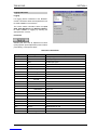
Manual Revision Record
Date Version No. Issue No. Change Comments
230801 1 1 First Issue
151001 1 2 Page 3.3 Buttons Proc Amp to Y
Gain, Size to Black New section 00 to V1.2 and 03
to V1.2issued
060302 1 3 Changes for new front panel Complete new manual issued
00 to V1.3, 01 to V1.2, 02 to
V1.2, 03 to V1.3, 04 to V1.3
290103 1 4 Luma response to 5 MHz ±3 dB New section 00 to V1.4 and 02
to V1.3 issued
110203 1 5 Linearity specification New section 00 to V1.5 and 02
to V1.4 issued
130203 1 6 TX version added New section 00 to V1.6 and 01
to V1.3 issued
170303 1 7 Techspec Y Response 5 MHz
+0.2 dB, -0.5 dB New section 00 to V1.7 and 02
to V1.5 issued
130603 2 1 Multilingual safety data and
mounting warning added to
section 00, 03, TX added section
01, opening the front panel data
added to section 03 and card
edge data added to section 04
Complete new manual issued
030703 2 2 UL Listed mark added section 00 Complete new manual issued
190504 2 3 Default output/Genlock additions
and PSP added Complete new manual issued
160904 2 4 RollCall Log fields added. New
section 5 with RollCall commands
added.
New issue released
201006 2 5 Logo and support data updated New issue released

TBS100/100D SECTION 1
TBS100OPS 20/10/06 www.snellwilcox.com Version 2 Issue 5 1.1
Description
The TBS100 provides multi-standard Y-C and
composite timebase correction and
synchronization. The composite input automatically
detects PAL, NTSC, NTSC-J, PAL-M, PAL-N, N4.4
and SECAM, and is sampled and decoded using
an adaptive line comb filter to ensure optimum
decoding performance. The signal correction
features include luminance and chrominance gain,
black level, NTSC hue, linear horizontal enhancer,
Y-C horizontal timing and picture position. The
TBS100D includes a vertical enhancer. Rugged
sync and clock recovery ensures reliable operation
with unstable and noisy inputs. In addition a
powerful frame recursive noise reducer
automatically eliminates much background noise.
A motion detector switches off the noise reduction
in moving picture areas.
The broadcast quality output encoder is fully
genlockable to a composite reference and
supports PAL, NTSC, NTSC-J, PAL-M, PAL-N and
SECAM. The TBS100 will also operate as a
transcoder between any of the available standards
of the same line rate. Serial digital component
outputs are available simultaneously on the
TBS100D.
Other features include freeze, pattern generation,
power-off composite bypass and GPI control/audio
delay flag output. Full RollCall remote control is
available including RollTrack for audio delay
tracking.
The TBS100/100D is designed to integrate up to
four IQ modules alongside its dedicated function.
This enables users to customize their unit
according to system needs.
The TX versions have a blank front panel with
RollCall only control.
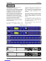
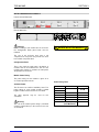
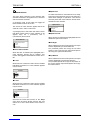
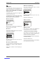
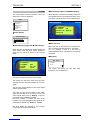
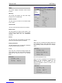
FRONT PANEL VIEWS
REAR PANEL VIEWS
TBS100/TBS100TX
Fuse
ROLLCALL
2
OUTPUTS INPUTS
2
Y
C
1
A
CVBS
GPI/O Y/B
CVBS
C
REFERENCE
100-240V~
60/50 Hz
1.8A
T
T2A H 250V
TBS100D/TBS100DTX
Fuse
ROLLCALL
2
OUTPUTS INPUTS
2
Y
C
1
2
1
A
CVBS
SERIAL OUT
GPI/O Y/B
CVBS
C
REFERENCE
100-240V~
60/50 Hz
1.8A
T
T2A H 250V

TBS100/100D SECTION 1
TBS100OPS 20/10/06 www.snellwilcox.com Version 2 Issue 5 1.2
Features
•
4:2:2 frame synchroniser / timebase corrector
• Input standards - PAL, NTSC, NTSC-J, PAL-N, PAL-M, N4.4.3 and SECAM
• Output standards - PAL, NTSC, NTSC-J, PAL-N, PAL-M and SECAM
• Auto standards detection
• Y-C and Composite input / output
• Handles VHS tape-playback feature modes
• Optional SDI output – SMPTE 259M –1997 (TBS100D)
• Adaptive line comb decoder
• Motion adaptive recursive noise reducer with automatic noise floor measurement
• PAL Hanover bar suppression
• Linear horizontal enhancer
• Vertical enhancer (TBS100D)
• Broadcast quality encoder
• Genlockable SPG with phasing adjustments
• Test signal generator (100/75% colour bars, multi-burst, black)
• VITS insertion on composite / YC outputs
• PAL Line 23 and NTSC Line 21 process, pass or blank
• Selectable Automatic Gain Control.
• Selectable ACC referenced to colour burst
• Adjustment of luma gain, black level, chroma gain, NTSC Hue and horizontal timing
• Frame freeze, black or input pass through on loss of input
• Power-down bypass (composite A in to composite 1 output)
• Vertical information passed or blanked on either composite/YC or SDI outputs (TBS100D)
• Delay Flag (GPI/O port) output and RollTrack™ for audio tracking
• Programmable GPI/O port
• 3 programmable memories
• Full RollCall remote control (including RollTrack for audio delay)
• Spare slot for S&W IQ modules (e.g. Stereo Audio Delay)

TBS100/100D SECTION 2
TBS100OPS 20/10/06 www.snellwilcox.com Version 2 Issue 5 2.1
Technical Profile
Features
Signal Inputs
Composite 2 x via BNC connectors
Separated Y/C S-VHS/Hi-8 via 2 x via BNC
connectors
Reference 1 via Loop-through BNC
connectors
Signal Outputs
Composite 2 x program outputs via BNC
connectors
Separated Y/C 1 x program output via 2 x BNC
connectors
Serial Component
(TBS100D version only)
2 x outputs via BNC connectors
Control Interface
GPI I/O 1x via BNC connector Closing
contact
RollCall Via BNC connector
(Single Source)
Remote S & W RollCall RS485 or RS422
at 38 kb via 9-pin D-type
connector (Optional)
Front Panel
Controls
Luminance Gain ±3 dB in 0.1 dB steps
Chrominance Gain ±3 dB in 0.1 dB steps
Black Level ±100 mV in 1.6 mV steps
NTSC Hue 360° in 1° steps
Luminance Noise
Reduce
Off, Low, Medium, High
Chrominance Noise
Reduce
Off, Low, Medium, High
Enhance (TBS100) H Enhance: Off, De-enhance,
Low, Medium, High
Enhance (TBS100D) H Enhance: Off, Low, Medium,
High
H Enhance Frequency: 2.25 MHz
and 3.375 MHz
V Enhance: Off, Low, Medium,
High
Y-C Timing ±1036 ns in 148 ns steps
Picture Position ±1036 ns in 148 ns steps
Genlock Off/On, ScH Lock, HV Lock
Frame Freeze Off/On
Memory Recall Select 1, 2 or 3
Pattern Select Black, Multi-burst, 100% bars,
75% bars
Preset Controls
Input Standard Select Standards in Auto detect: NTSC,
PAL, PAL-M, NTSC-J, PAL-N,
SECAM, NTSC4.43
Output Standard 625 PAL, PAL-M, PAL-N,
Output Standard 525 NTSC, PAL-M, NTSC-J,
AGC On/Off
(Auto Gain Range +3 dB to -6 dB)
ACC On/Off
Genlock H-Phase ±113 µs
Genlock Subcarrier
Phase
±180°
Memory Store / Recall / Clear
Insert VITS On / Off
Pass vertical data
(encoder)
On / Off
Pass vertical data
(SDI output)
On / Off (TBS100D only)
PAL Line 23 Process As video / Pass / Blank
NTSC Line 21 Process As video / Pass / Blank
SECAM Notch filter On / Off
SECAM Bottles On / Off
SECAM Carrier On / Off
SECAM Chroma Pre-
Filter
On / Off
Noise Reduction Split
screen
Off / Top Bottom split, Left Right
split
Default Output Input, Pattern, Freeze, Stable Input
Logging (via RollCall) Reference, Input State, Input
Standard
GPI action Memory 1, 2, 3 Pattern, Freeze
GPI Output Off, [On - Delay Flag, Input Loss,
polarity high/low]
RollTrack Setup Enable Unit 1…8
Preset Memories Returns all memory settings to
factory defaults
Preset Unit Returns unit to factory defaults
Indicators
Input Loss Input Select LED Illuminates
Input Error Input Error LED flashes
Reference Loss Genlock Select LED Illuminates

TBS100/100D SECTION 2
TBS100OPS 20/10/06 www.snellwilcox.com Version 2 Issue 5 2.2
Specifications
Input
Return Loss Better than -35 dB to 5 MHz
Composite Level 1 V pk-pk typ. Into 75 ohms
Y Level 1 V pk-pk into 75 Ohms
C Level Color Burst at standard level into
75 Ohms
Reference Level Composite or Black Burst at
standard level via loop-thru
connection. (>10k)
Performance
Sampling 4:2:2 (13.5 MHz)
Y Frequency Response 5 MHz +0.2 dB, -0.5 dB
C Frequency Response Better than 1.5 MHz -3 dB
2T Pulse Shape K-
rating
Better than 1%
Signal to Noise Ratio Better than 60 dB (Weighted,
Ramp)
Subcarrier Rejection Better than 46 dB (PAL and
NTSC) 75% Red
Return Loss: Inputs better than 35 dB to 5.0 MHz
Return Loss: Outputs better than 35 dB to 5.0 MHz
Return Loss SDI
Outputs
better than 15 dB at 270 MHz
Power
Mains Supply 115/230V 60/50 Hz 1.2 A
Power
Consumption
140 W max
Mechanical
Temperature Range 0° to 40° C operating
Cooling Axial fan
Case Type 1RU Rack Mounting
Dimensions Overall 483 x 440 x 45 mm.
(w x d x h).
Depth from mounting face (including
unmated connectors) 415 mm.
Weight 9.75 kg
EMC Environment This unit is intended for use in the
commercial and light industrial
environment E2.

TBS100/100D SECTION 3
TBS100OPS 20/10/06 www.snellwilcox.com Version 2 Issue 5 3.1
Installation
Unpacking the TBS100/TBS100D
The unit is packed in a single carton. The contents
of the flight case are as follows:
• 1U Mainframe fitted with TBS100 card
• Power cable
• Operator's Manual
Unpack the carton carefully and check for any
shortages or shipping damage. Immediately report
any shortages or damage to Snell and Wilcox
Limited.
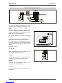
POWER CONNECTIONS
Power Supply
Mains power is supplied to the unit via a filtered IEC
connector.
The mains power fuse rating is 2 A (T) HBC and the
rated current for the unit is 1.2 A.
The power supply ON/OFF switch is located on the
front of the power supply inside the front panel.
CAUTION: THE VENTILATION HOLES AT THE
SIDES OF THE UNIT AND THE FAN EXIT AREA
MUST NOT BE OBSCURED.
Supply Voltage
The power supplies are auto switching for input
voltages in the ranges of 100 V to 250 V nominal.
No voltage adjustment procedure is required.
CAUTION: THIS UNIT MUST NOT BE
OPERATED WITHOUT
AN EARTH CONNECTION.
Fuse
100-240V~
60/50 Hz
1.8A
T
T2A H 250V
Rack Mounting the 1U Enclosure
The product must not be rack mounted using only the front rack mounting ears. When installing the product in
a rack one of the following methods must be used: -
• Place the unit on a suitably specified, and installed rack shelf and secure the product to the rack via the
front rack ears
• Alternatively fit the unit using additional rear rack mounts
A suitable mounting kit is available for purchase from Snell & Wilcox by quoting the order code:
FGACK RACK-MNT-KIT
Note: The rear mounting brackets must be attached using the two M3 threaded inserts on both sides of the
product; the maximum length of screw that can be used is M3 x 6mm. Ensure that the product is secured to
the rack in all four corners.

TBS100/100D SECTION 3
TBS100OPS 20/10/06 www.snellwilcox.com Version 2 Issue 5 3.2
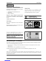
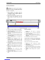
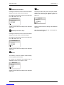
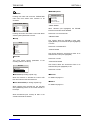
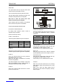
INPUT CONNECTIONS
Composite A and B
These are the 2 Composite video inputs to the
decoder module via BNC connectors. Nominal input
level is 1 V p-p terminated in 75 Ohms.
Separated Y C
A Y-C (S-VHS, Hi-8 etc.) input signal may be
connected to the unit via 2 BNC connectors marked
Y and C.
Y input level is a nominal 1V p-p into 75 Ohms.
C input is nominal colour burst level into 75 Ohms.
Reference Input
When suitable signals are connected to this input,
the video output of the unit will be fully synchronised
to the reference signal source when the genlock
function is selected. If no signal is present the unit
will automatically revert to internal free-running
operation.
BNC loop-through connectors are provided and the
signal may be black burst or composite video at
standard level.
GPI I/O
This BNC connector provides GPI input and output
control for the module.
Input Functions Selects pattern as output.
Recalls memory.
Selects freeze function.
Output Functions Provides a flag representing the
video delay through the unit.
Indicates a loss of input signal
and the Input line standard.
I
N
P
U
T
S
A
Y/B
CVBS
I
N
P
U
T
S
A
Y/B
C
2
R
E
F
E
R
E
N
C
E
GPI/O

TBS100/100D SECTION 3
TBS100OPS 20/10/06 www.snellwilcox.com Version 2 Issue 5 3.3
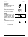
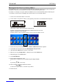
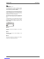
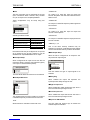
OUTPUT CONNECTIONS
Composite Outputs 1 & 2
Two isolated composite outputs are available from
these BNC connectors.
Output level is standard 1V p-p into 75 Ohms.
SDI 1 & 2 (TBS100D only)
These are the 2 SDI outputs of the unit via BNC
connectors.
Y-C Separated Output
A Y-C (S-VHS/Hi-8) output signal is available via
these 2 BNC connectors marked Y and C.
Y output level is a nominal 1 V p-p into 75 Ohms
C output is a nominal colour burst level into 75
Ohms
COMMUNICATION CONNECTORS
Remote
This 9 pin `D' connector on the rear panel allows
the unit to be connected to the RollCall 485 network
communications system. This connector may also
be used as a RS422 port. For more information see
RollCall section.
RollCall
This single BNC connector allows the unit to be
connected to the RollCall network communications
system.
2
1
CVBS
2
1
SERIAL OUT
O
U
T
P
U
T
S
Y
C
2
1
ROLLCALL

TBS100/100D SECTION 3
TBS100OPS 20/10/06 www.snellwilcox.com Version 2 Issue 5 3.4
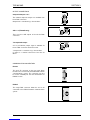
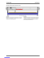
OPENING AND CLOSING THE FRONT PANEL
To Open
Release the front panel by pulling the front panel
forward and downwards using the release handles
on either side of the front panel.
To Close
Replace the front panel by pushing the front panel
rearwards and upwards using the release handles
on either side of the front panel. Ensure that the
panel is fully seated in the case.
La pagina si sta caricando...
La pagina si sta caricando...
La pagina si sta caricando...
La pagina si sta caricando...
La pagina si sta caricando...
La pagina si sta caricando...
La pagina si sta caricando...
La pagina si sta caricando...
La pagina si sta caricando...
La pagina si sta caricando...
La pagina si sta caricando...
La pagina si sta caricando...
La pagina si sta caricando...
La pagina si sta caricando...
La pagina si sta caricando...
La pagina si sta caricando...
La pagina si sta caricando...
La pagina si sta caricando...
La pagina si sta caricando...
La pagina si sta caricando...
La pagina si sta caricando...
La pagina si sta caricando...
La pagina si sta caricando...
La pagina si sta caricando...
La pagina si sta caricando...
La pagina si sta caricando...
La pagina si sta caricando...
La pagina si sta caricando...
La pagina si sta caricando...
La pagina si sta caricando...
La pagina si sta caricando...
La pagina si sta caricando...
La pagina si sta caricando...
La pagina si sta caricando...
La pagina si sta caricando...
La pagina si sta caricando...
La pagina si sta caricando...
La pagina si sta caricando...
La pagina si sta caricando...
La pagina si sta caricando...
La pagina si sta caricando...
La pagina si sta caricando...
La pagina si sta caricando...
La pagina si sta caricando...
La pagina si sta caricando...
La pagina si sta caricando...
La pagina si sta caricando...
-
 1
1
-
 2
2
-
 3
3
-
 4
4
-
 5
5
-
 6
6
-
 7
7
-
 8
8
-
 9
9
-
 10
10
-
 11
11
-
 12
12
-
 13
13
-
 14
14
-
 15
15
-
 16
16
-
 17
17
-
 18
18
-
 19
19
-
 20
20
-
 21
21
-
 22
22
-
 23
23
-
 24
24
-
 25
25
-
 26
26
-
 27
27
-
 28
28
-
 29
29
-
 30
30
-
 31
31
-
 32
32
-
 33
33
-
 34
34
-
 35
35
-
 36
36
-
 37
37
-
 38
38
-
 39
39
-
 40
40
-
 41
41
-
 42
42
-
 43
43
-
 44
44
-
 45
45
-
 46
46
-
 47
47
-
 48
48
-
 49
49
-
 50
50
-
 51
51
-
 52
52
-
 53
53
-
 54
54
-
 55
55
-
 56
56
-
 57
57
-
 58
58
-
 59
59
-
 60
60
-
 61
61
-
 62
62
-
 63
63
-
 64
64
-
 65
65
-
 66
66
-
 67
67


in altre lingue
- English: Snell & Wilcox TBS100 User manual
Altri documenti
-
 Snell Advanced Media IQEDGE-40-18B Manuale utente
-
 Snell Advanced Media IQMIX26 Manuale utente
-
AJA FS4 Installation and Operation Guide
-
Carel KEC010 Guida d'installazione
-
RCS ESC-006A Manuale del proprietario
-
Tascam BR-20 Series Operation & Maintenance Manual
-
Juniper MX10003 Hardware Guide
-
-
-
 Calpeda GK Istruzioni per l'uso


