Dometic MagicTouch MT400 Istruzioni per l'uso
- Tipo
- Istruzioni per l'uso

1
2
3
4
5
6
7
1
8
9
11
12
10
14
13
15
16
17
18
+ 12V
rt
sw
15 A
30
31
15
gn
ge
sw/ws
sw/gn
sw
or
1
6
7
2
5
4
3
rt/sw
bl/ge
bl/rt
rt/ge
gn
bl
gr/ge
gr/rt
2
3
4
5
6
7
8
9
15
17
18
14
1
11
12
10
13
16
+12 V
100 mA
ML-11
100 mA
+12 V
+12 V
rt/sw
bl/ge
bl/rt
rt/ge
gr/ge
gr/rt
2
3
4
5
6
7
1
8
9
11
12
10
13
15
16
17
18
14
1
23
rt/sw
bl/ge
bl/rt
rt/ge
gr/ge
gr/rt
2
3
5
6
7
1
8
9
11
12
10
13
15
16
17
18
14
4
+12 V
100 mA
+12 V
+12 V
1
23
2.
A
B
1.
1
2
3
MagicTouch MT400
EN: 8
DE: 28
FR: 48
ES: 70
PT: 92
IT: 113
NL: 135
DA: 155
SV: 175
NO: 195
FI: 215
RU: 236
PL: 259
SK: 280
CS: 300
HU: 320
EN: 4
DE: 24
FR: 44
ES: 66
PT: 88
IT: 109
NL: 131
DA: 151
SV: 171
NO: 191
FI: 211
RU: 231
PL: 255
SK: 276
CS: 296
HU: 316
EN: 5
DE: 25
FR: 45
ES: 67
PT: 89
IT: 110
NL: 132
DA: 152
SV: 172
NO: 192
FI: 212
RU: 233
PL: 256
SK: 277
CS: 297
HU: 317
EN: 7
DE: 27
FR: 47
ES: 69
PT: 91
IT: 112
NL: 134
DA: 154
SV: 174
NO: 194
FI: 214
RU: 235
PL: 258
SK: 279
CS: 299
HU: 319
EN: 7
DE: 27
FR: 47
ES: 69
PT: 91
IT: 112
NL: 134
DA: 154
SV: 174
NO: 194
FI: 214
RU: 235
PL: 258
SK: 279
CS: 299
HU: 319
EN: 4
DE: 24
FR: 44
ES: 66
PT: 88
IT: 109
NL: 131
DA: 151
SV: 171
NO: 191
FI: 211
RU: 232
PL: 255
SK: 276
CS: 296
HU: 316
EN DE FR ES PT IT NL DA
bl Blue Blau Bleu Azul Azul Blu Blauw Blå
br Brown Braun Marron Marrón Castanho Marrone Bruin Brun
ge Yellow Gelb Jaune Amarillo Amarelo Giallo Geel Gul
gn Green Grün Vert Verde Verde Verde Groen Grøn
gr Grey Grau Gris Gris Cinzento Grigio Grijs Grå
or Orange Orange Orange Naranja Cor de laranja Arancione Oranje Orange
pk Pink Pink Rosa Rose Cor de rosa Rosa Roze Lyserøde
rt Red Rot Rouge Rojo Vermelho Rosso Rood Rød
sw Black Schwarz Noir Negro Preto Nero Zwart Sort
ws White Weiß Blanc Blanco Branco Bianco Wit Hvid
SV NO FI RU PL SK CS HU
bl Blå Blå Sininen Синий Niebieski Modrá Modrá Kék
br Brun Brun Ruskea Коричневый Brązowy Hnedá Hněda Barna
ge Gul Gul Keltainen Желтый Żółty Žltá Žlutá Sárga
gn Grön Grønn Vihreä Зеленый Zielony Zelená Zelená Zöld
gr Grå Grå Harmaa Серый Szary Sivá Šedá Szürke
or Orange Oransje Oranssi Оранжевый Pomarańczowy Oranžová Oranžová Narancs
pk Rosa Rosa Pinkki Розовый Różowy Ružová Růžová Rózsaszín
rt Röd Rød Punainen Красный Czerwony Červená Červená Piros
sw Svart Svart Musta Черный Czarny Čierna Černá Fekete
ws Vit Hvit Valkoinen Белый Biały Biela Bílá Fehér
1
2
4
3
5
6
7
8
9
MT400--IO--16s.book Seite 1 Donnerstag, 25. August 2016 2:34 14

2
Dometic WAECO International GmbH
Hollefeldstrasse 63
D-48282 Emsdetten
www.dometic.com
+ COMFORT
COMFORT
AUTOLOCK
1x
2x
1min
COMFORT
ON
ON
+ OFF
2s
10x
rt/sw
bl/ge
bl/rt
rt/ge
gr/ge
gr/rt
2
3
4
5
6
7
1
8
9
11
12
10
13
15
16
17
18
14
1
23
rt/sw
bl/ge
bl/rt
+12 V
rt/ge
gr/ge
gr/rt
2
3
4
5
6
7
1
8
9
11
12
10
13
15
16
17
18
14
1
2
3
magic lock
Pi
n5
Pi
n10
rt/sw
bl/ge
bl/rt
rt/ge
gr/ge
gr/rt
2
3
4
5
6
7
1
8
9
11
12
10
13
15
16
17
18
14
rt/sw
bl/ge
bl/rt
rt/ge
gr/ge
gr/rt
2
3
4
5
6
7
1
8
9
11
12
10
13
15
16
17
18
14
+12 V
+12 V
32
1
56b
br
pk
31
13
15
16
17
18
14
30
56b
10 A
br
pk
13
15
16
17
18
14
ON
ON
+ OFF
COMFORT
0,7s
COMFORT
3s 1x1x
2x
1x
2x
1x
2x
1x
2x
2x
3x
4x
1x
3x
3x
2x
A
B
EN: 17
DE: 37
FR: 59
ES: 81
PT: 102
IT: 124
NL: 144
DA: 164
SV: 184
NO: 204
FI: 224
RU: 248
PL: 269
SK: 289
CS: 309
HU: 329
EN: 18
DE: 38
FR: 60
ES: 82
PT: 103
IT: 125
NL: 145
DA: 165
SV: 185
NO: 205
FI: 225
RU: 249
PL: 270
SK: 290
CS: 310
HU: 330
EN: 20
DE: 40
FR: 62
ES: 84
PT: 105
IT: 127
NL: 147
DA: 167
SV: 187
NO: 207
FI: 227
RU: 251
PL: 272
SK: 292
CS: 312
HU: 332
EN: 9
DE: 29
FR: 49
ES: 71
PT: 93
IT: 114
NL: 136
DA: 156
SV: 176
NO: 196
FI: 216
RU: 237
PL: 260
SK: 281
CS: 301
HU: 321
EN DE FR ES PT IT NL DA
bl Blue Blau Bleu Azul Azul Blu Blauw Blå
br Brown Braun Marron Marrón Castanho Marrone Bruin Brun
ge Ye l l o w Gelb Jaune Amarillo Amarelo Giallo Geel Gul
gn Green Grün Vert Verde Verde Verde Groen Grøn
gr Grey Grau Gris Gris Cinzento Grigio Grijs Grå
or Orange Orange Orange Naranja Cor de laranja Arancione Oranje Orange
pk Pink Pink Rosa Rose Cor de rosa Rosa Roze Lyserøde
rt Red Rot Rouge Rojo Vermelho Rosso Rood Rød
sw Black Schwarz Noir Negro Preto Nero Zwart Sort
ws White Weiß Blanc Blanco Branco Bianco Wit Hvid
SV NO FI RU PL SK CS HU
bl Blå Blå Sininen Синий Niebieski Modrá Modrá Kék
br Brun Brun Ruskea Коричневый Brązowy Hnedá Hněda Barna
ge Gul Gul Keltainen Желтый Żółty Žltá Žlutá Sárga
gn Grön Grønn Vihreä Зеленый Zielony Zelená Zelená Zöld
gr Grå Grå Harmaa Серый Szary Sivá Šedá Szürke
or Orange Oransje Oranssi Оранжевый Pomarańczowy Oranžová Oranžová Narancs
pk Rosa Rosa Pinkki Розовый Różowy Ružová Růžová Rózsaszín
rt Röd Rød Punainen Красный Czerwony Červená Červená Piros
sw Svart Svart Musta Черный Czarny Čierna Černá Fekete
ws Vit Hvit Valkoinen Белый Biały Biela Bílá Fehér
a
b
d
e
f
g
0
c
4445101746 08/2016
MT400--IO--16s.book Seite 2 Donnerstag, 25. August 2016 2:34 14

MT400
Radio Remote Control
Installation and Operating Manual . . . . . . 3
Funk-Fernbedienung
Montage- und Bedienungsanleitung . . . 23
Radiotélécommande
Instructions de montage
et de service . . . . . . . . . . . . . . . . . . . . . . . 43
Mando a distancia por radio
Instrucciones de montaje y de uso . . . . .65
Controle remoto sem fio
Instruções de montagem e manual de
instruções . . . . . . . . . . . . . . . . . . . . . . . . . 87
Radiotelecomando
Istruzioni di montaggio e d’uso . . . . . . . 108
Draadloze afstandsbediening
Montagehandleiding en
gebruiksaanwijzing. . . . . . . . . . . . . . . . . 130
Radio-fjernbetjening
Monterings- og betjeningsvejledning. . 150
Radio – fjärrkontroll
Monterings- och bruksanvisning . . . . . . 170
Radio-fjernkontrol
Monterings- og bruksanvisning . . . . . . 190
Radiokauko-ohjain
Asennus- ja käyttöohje. . . . . . . . . . . . . . 210
Система дистанционного
радиоуправления
Инструкция по монтажу
и эксплуатации. . . . . . . . . . . . . . . . . . . . 230
Moduł sterowania radiowego
Instrukcja montażu i obsługi . . . . . . . . . 254
Diaľkové ovládanie
Návod na montáž a uvedenie
do prevádzky . . . . . . . . . . . . . . . . . . . . . 275
Dálkové ovládání
Návod k montáži a obsluze . . . . . . . . . . 295
Vezeték nélküli távirányító
Szerelési és használati útmutató . . . . . . 315
EN
DE
FR
ES
PT
IT
NL
DA
SV
NO
FI
RU
PL
SK
CS
HU
DRIVING SUPPORT
MAGICTOUCH
MT400--IO--16s.book Seite 1 Donnerstag, 25. August 2016 2:37 14

MT400--IO--16s.book Seite 2 Donnerstag, 25. August 2016 2:37 14

MT400 Explanation of symbols
EN
3
Please read this instruction manual carefully before installation and first use, and store
it in a safe place. If you pass on the product to another person, hand over this instruc-
tion manual along with it.
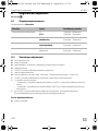
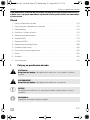
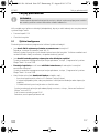
Table of contents
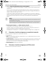
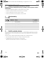
1 Explanation of symbols. . . . . . . . . . . . . . . . . . . . . . . . . . . . . . . . . . . . . . . . . . . . . . . . . . . . . . . 3
2 Safety and installation instructions . . . . . . . . . . . . . . . . . . . . . . . . . . . . . . . . . . . . . . . . . . . . . .4
3 Scope of delivery . . . . . . . . . . . . . . . . . . . . . . . . . . . . . . . . . . . . . . . . . . . . . . . . . . . . . . . . . . . 4
4 Intended use. . . . . . . . . . . . . . . . . . . . . . . . . . . . . . . . . . . . . . . . . . . . . . . . . . . . . . . . . . . . . . . 4
5 Instructions before installation . . . . . . . . . . . . . . . . . . . . . . . . . . . . . . . . . . . . . . . . . . . . . . . . . 5
6 Installing MT400. . . . . . . . . . . . . . . . . . . . . . . . . . . . . . . . . . . . . . . . . . . . . . . . . . . . . . . . . . . . 7
7 Connecting MT400 . . . . . . . . . . . . . . . . . . . . . . . . . . . . . . . . . . . . . . . . . . . . . . . . . . . . . . . . . 7
8 Programming MagicTouch . . . . . . . . . . . . . . . . . . . . . . . . . . . . . . . . . . . . . . . . . . . . . . . . . . 17
9 Operating MagicTouch . . . . . . . . . . . . . . . . . . . . . . . . . . . . . . . . . . . . . . . . . . . . . . . . . . . . . 18
10 MagicTouch care and cleaning . . . . . . . . . . . . . . . . . . . . . . . . . . . . . . . . . . . . . . . . . . . . . . . 21
11 Guarantee . . . . . . . . . . . . . . . . . . . . . . . . . . . . . . . . . . . . . . . . . . . . . . . . . . . . . . . . . . . . . . . . 21
12 Disposal. . . . . . . . . . . . . . . . . . . . . . . . . . . . . . . . . . . . . . . . . . . . . . . . . . . . . . . . . . . . . . . . . . 21
13 Technical data. . . . . . . . . . . . . . . . . . . . . . . . . . . . . . . . . . . . . . . . . . . . . . . . . . . . . . . . . . . . .22
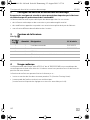
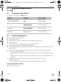
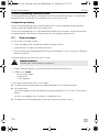
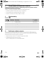
1 Explanation of symbols
!
!
A
I
WARNING!
Safety instruction: Failure to observe this instruction can cause fatal or serious injury.
CAUTION!
Safety instruction: Failure to observe this instruction can lead to injury.
NOTICE!
Failure to observe this instruction can cause material damage and impair the function
of the product.
NOTE
Supplementary information for operating the product.
MT400--IO--16s.book Seite 3 Donnerstag, 25. August 2016 2:37 14

Safety and installation instructions MT400
EN
4
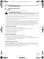
2 Safety and installation instructions
Please observe the prescribed safety instructions and stipulations from the vehicle
manufacturer and service workshops.
The manufacturer accepts no liability for damage in the following cases:
• Damage to the product resulting from mechanical influences and excess voltage
• Alterations to the product without express permission from the manufacturer
• Use for purposes other than those described in the operating manual
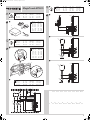
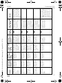
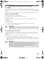
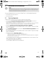
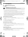
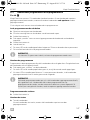
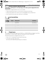
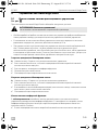
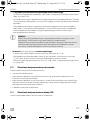
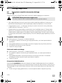
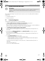
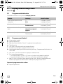
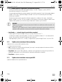
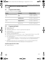
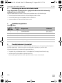
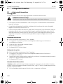
3Scope of delivery
See fig. 2
4Intended use
The MagicTouch MT400 radio remote control (item no. 9600000389) supplements the central
locking system of your vehicle. You open and close the doors of your vehicle using a hand-held
transmitter.
The following can be operated by remote control using the convenience function, e. g.
• the dipped headlights can be switched on for 10 sec. (coming home function) or
• electric power windows and sliding roof can be activated
(as long as this is factory-set and operable by key).
No. in
fig. 2
Quantity Designation Item no.
1 1 Controller 9101300011
2 2 Hand-held transmitter 9600000372
3 1 Status LED
– 1 Control unit connection cable
––Fastening material
MT400--IO--16s.book Seite 4 Donnerstag, 25. August 2016 2:37 14

MT400 Instructions before installation
EN
5
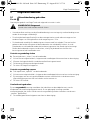
5 Instructions before installation
I
Your vehicle should meet the following requirements to be able to open and close it with
MagicTouch:
• 12 V operating voltage
• Central locking system
5.1 Setting the configuration
Clarify the following before installing and programming the system:
• Is the driver's door equipped with its own servo motor for locking?
If no: retrofit a servo motor (e. g. ML-11).
Some manufacturers equip their vehicles with a power-saving central locking system. In these
vehicles, there is no servo motor in the driver's door; there is an electrical switch instead.
• Do the door contacts have a negative or positive charge?
The system must be programmed accordingly, see chapter “Programming MagicTouch” on
page 17.
• Is it permitted by law in your country for the warning system to flash when opening and
closing the central locking system?
The system must be programmed accordingly, see chapter “Programming MagicTouch” on
page 17.
• What should the convenience function control, e. g.:
– the dipped headlights for 10 sec. (coming home function)
In this case, clarify whether the dipped headlights are positively or negatively charged.
– electric power windows and sliding roof.
The system must be connected and set up accordingly, see chapter “Setting up the conveni-
ence function” on page 9.
Is the maximum power of 10 A sufficient?
If no, an additional relay must be used.
NOTE
If you do not have sufficient technical knowledge for installing and connecting
components in vehicles, you should have a specialist install the radio remote control in
your vehicle.
MT400--IO--16s.book Seite 5 Donnerstag, 25. August 2016 2:37 14

Instructions before installation MT400
EN
6
• What type of switching function does the original central locking system have?
The system must be programmed accordingly, see chapter “Connecting MT400 to the cen-
tral locking system” on page 8.
You will require the circuit diagram for the central locking system to do so. You can obtain this
from your vehicle dealership. There is corresponding information for some vehicle in chapter
“Vehicle-specific data” on page 9.
If no original circuit diagrams are available and you cannot find your vehicle in the table in
chapter “Vehicle-specific data” on page 9, you will need to determine the function of the
control cables that run from the control unit for the central locking system to the vehicle
doors.
A
• How long does the central locking system have to be activated for?
The activation time for MagicTouch was set to 0.7 sec. at the factory.
In some vehicles, for example Mercedes, an activation time of 0.7 sec. might not be sufficient
to completely activate the central locking system.
To program the system to 3 sec., see chapter “Programming MagicTouch” on page 17.
5.2 Determining the installation location for the control unit
Select the installation location for the control unit:
• in the vehicle interior,
• not in areas where strong electrical fields could cause interference, e. g. ignition cables or
central control electronics,
• not in the immediate vicinity of other control units, in order to prevent the devices from
interfering with each other (which could cause malfunctions and reduce the range of the radio
remote control),
• not directly next to ventilator nozzles.
5.3 Determining the installation location for the status LED
Select a position on the dashboard.
NOTICE!
Only connect MagicTouch using the control cables for the central locking and not
using other cables.
Connection to other cables than the control cables or using an incorrect circuit plan
can lead to defects in the central locking system and the remote control.
MT400--IO--16s.book Seite 6 Donnerstag, 25. August 2016 2:37 14

MT400 Installing MT400
EN
7
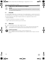
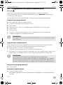
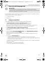
6 Installing MT400
See fig. 4
➤ Screw the control unit firmly to the vehicle with the screws supplied (B) or use double-sided
adhesive tape (A).
➤ Fix the status LED to the dashboard with double-sided adhesive tape.
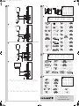
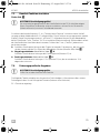
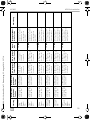
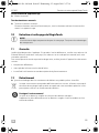
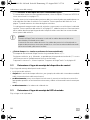
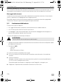
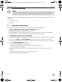
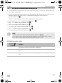
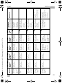
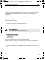
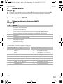
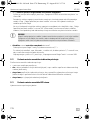
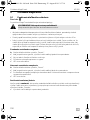
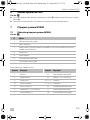
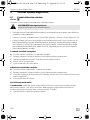
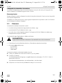
7 Connecting MT400
7.1 Connecting MT400 to the power
See fig. 5
The control unit has the following connections:
No. Designation
1 Indicator relay
2Interior lighting
3 Diode 1N4002
4Status LED
5 Door contact switch
6 Right-hand indicator
7Left-hand indicator
Termi n a l Connection Termi n a l Connection
1 Antenna 8 Left-hand indicator
2 (not assigned) 9 Battery, +12 V, terminal 30
3 Status LED 10, 11, 12 Closed
4 Interior lighting 13, 14, 15 Open
5 Earth, terminal 31 16 Convenience output
6 Ignition, +12 V, terminal 15 17 Convenience input
7 Door contact +/– 18 Right-hand indicator
MT400--IO--16s.book Seite 7 Donnerstag, 25. August 2016 2:37 14

Connecting MT400 MT400
EN
8
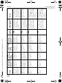
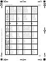
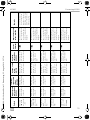
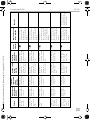
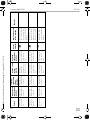
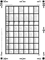
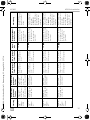
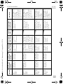
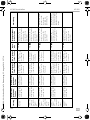
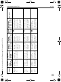
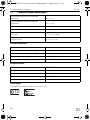
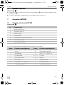
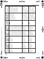
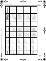
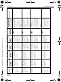
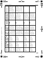
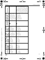
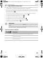
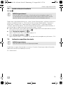
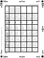
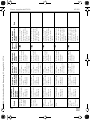
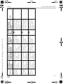
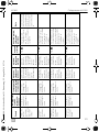
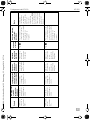
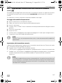
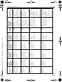
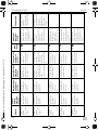
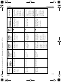
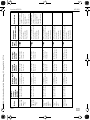
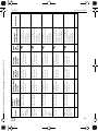
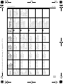
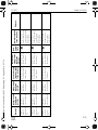
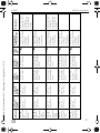
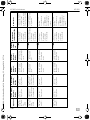
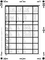
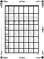
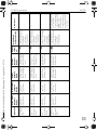
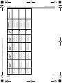
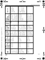
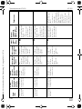
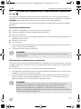
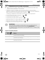
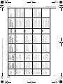
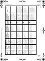
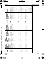
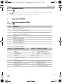
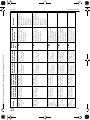
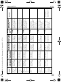
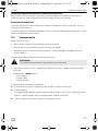
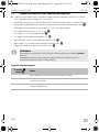
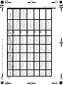
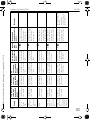
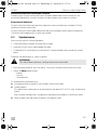
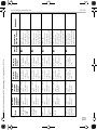
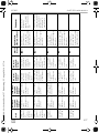
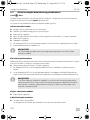
7.2 Connecting MT400 to the central locking system
➤ Connect MagicTouch in accordance with the corresponding circuit diagram (for details, see
table chapter “Keys for the circuit diagrams” on page 8):
• Vehicles without a servo motor in the driver's door (driver's door cannot be locked and
unlocked from the passenger's door) or with pressure vacuum central locking without electrical
control cable: fig. 7
In these cases, you will require an additional servo motor, type no. ML-11 for the driver's door.
• Two cables switching from negative to +12 V: fig. 8
• Two +12 V pulse control cables: fig. 9
• Two negative pulse control cables: fig. 0
• One open and negative pulse control cable: fig. a
• One +12 V and negative pulse control cable: fig. b
• Connection to the central locking system ML-44(22): fig. c
I
Keys for the circuit diagrams
NOTE
Check whether the indicators flash once upon locking with the remote control.
If they flash twice, you will need to reconnect the grey/yellow cable to pin 12 and the
blue/yellow cable to pin 13 of the control unit.
No. in fig. 7
to fig. c
Designation
1 Control unit for the vehicle's own central locking system
2 Control switch (driver's door) for the original central locking system,
central locking closed
3 Control switch (driver's door) for the original central locking system,
central locking open
MT400--IO--16s.book Seite 8 Donnerstag, 25. August 2016 2:37 14

MT400 Connecting MT400
EN
9
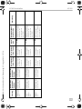
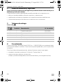
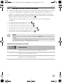
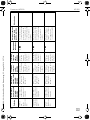
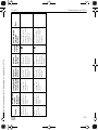
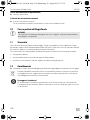
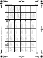
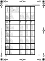
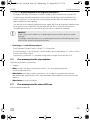
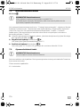
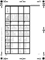
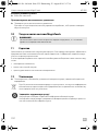
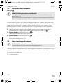
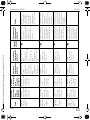
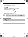
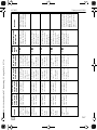
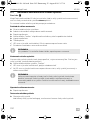
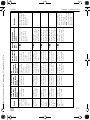
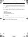
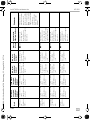
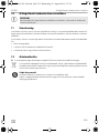
7.3 Setting up the convenience function
See fig. d
A
You can also set the convenience function to be a “coming home function”, for example: during
locking, the dimmed headlight is switched on for 10 sec. The function has to be programmed
(chapter “Programming MagicTouch” on page 17). You can also switch the dipped headlights on
by pressing the “Comfort” button for 10 sec (factory setting). While the convenience function is
running, this can be switched off at any time by pressing the “Comfort” button again.
➤ Connect the pink cable to the original vehicle cable which originates from the light switch and
which connects the positive signal for the dipped headlights (terminal 56b, fig. d).
➤ Negatively-connected dipped headlights (fig. d A):
Connect the brown cable to the vehicle earth (Terminal 31).
➤ Positively-connected dipped headlights (fig. d B):
Connect the brown cable to +12 V (Terminal 30), which must be protected with at least 10 A.
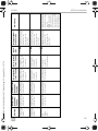
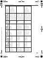
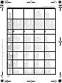
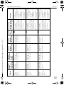
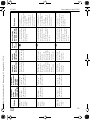
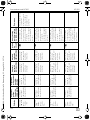
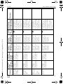
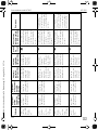
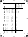
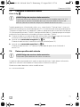
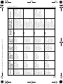
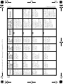
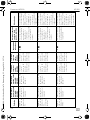
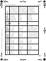
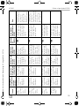
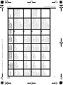
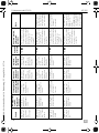
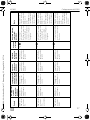
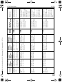
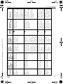
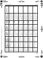
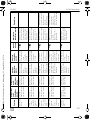
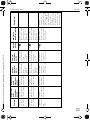
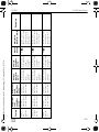
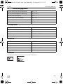
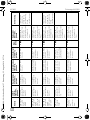
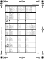
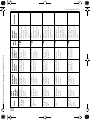
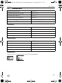
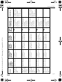
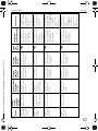
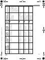
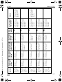
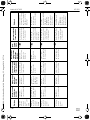
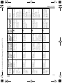
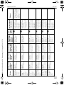
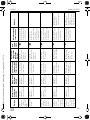
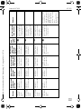
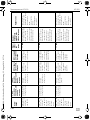
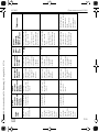
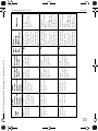
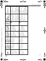
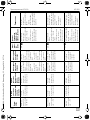
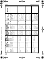
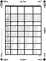
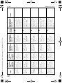
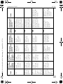
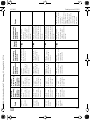
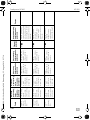
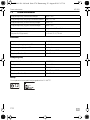
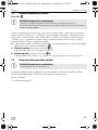
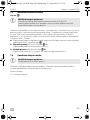
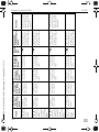
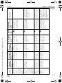
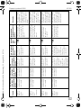
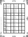
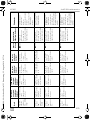
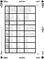
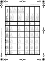
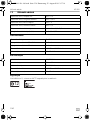
7.4 Vehicle-specific data
A
The following table does not claim to be exhaustive. You can obtain information on other vehicles
on request from Dometic (see address on the back).
We reserve the right to make alterations.
CL = central locking
NOTICE! Risk of damage
The maximum output current of 10 A for the convenience function may not be
exceeded.
If you would like to activate larger consumers, you will need to use an additional relay
(operating current relay) with a recovery diode.
NOTICE! Risk of damage
Check the polarity before connecting.
MT400--IO--16s.book Seite 9 Donnerstag, 25. August 2016 2:37 14

Connecting MT400 MT400
EN
10
Vehicle
Indicator left,
cable colour,
position
Indicator
right, cable
colour,
position
CL open, cable
colour,
position
CL closed,
cable colour,
position
Circuit
diagram
Door contact, cable
colour, position
Remarks
Audi 80 type
89 and B4,
constr. year:
86–94
Black/white,
cable strand left
on the sill
Black/green,
cable strand left
on the sill
Green/blue,
A pillar left
Green/blue,
A pillar left
fig. b Brown/white, on the
door contact front left
on the A pillar, door
contact is negatively
charged
connect the blue/red
control cable in the
direction of the door
and the grey/yellow
cable in the direction
of the CL-pump
Audi 100 And
A6 type C4,
constr. year:
90–97 with
theft
protection
Black/white,
cable strand left
on the sill
Black/green,
cable strand left
on the sill
Brown/green,
A pillar left,
coming out of
the driver's door
Brown/grey,
A pillar left,
coming out of
the driver's door
fig. 0 Brown/yellow, on the
door contact front left
on the A pillar, door
contact is negatively
charged
Audi 100 And
A6 type C4,
constr. year:
90–97
without theft
protection
Black/white,
cable strand left
on the sill
Black/green,
cable strand left
on the sill
Green/blue,
A pillar left,
coming out of
the driver's door
Green/blue,
A pillar left,
coming out of
the driver's door
fig. b Brown/yellow on the
door contact front left
on the A pillar, door
contact is negatively
charged
connect the blue/red
control cable in the
direction of the door
and the grey/yellow
cable in the direction
of the CL-pump
Audi A3 type
8L, constr.
year: 96–01
Black/white,
cable strand left
on the sill
Black/green,
cable strand left
on the sill
Grey/black,
A pillar left,
coming out of
the driver's door
Brown/red or
grey,
A pillar left,
coming out of
the driver's door
fig. 0 Brown/white, on the
door contact front left
on the A pillar, door
contact is negatively
charged
Audi A4 type
B5 constr.
year: 94–...
with theft
protection
Black/white,
cable strand left
on the sill
Black/green,
cable strand left
on the sill
Grey/white,
A pillar left,
coming out of
the driver's door
Brown/grey,
A pillar left,
coming out of
the driver's door
fig. 0 Brown/white, on the
door contact front left
on the A pillar, door
contact is negatively
charged
MT400--IO--16s.book Seite 10 Donnerstag, 25. August 2016 2:37 14

MT400 Connecting MT400
EN
11
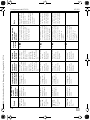
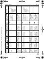
Audi A4 type
B5, constr.
year: 94–...
without theft
protection
Black/white,
cable strand left
on the sill
Black/green,
cable strand left
on the sill
Green/blue,
A pillar left,
coming out of
the driver's door
Green/blue,
A pillar left,
coming out of
the driver's door
fig. b Grey, on the door
contact front left on
the A pillar, door
contact is negatively
charged
connect the blue/red
control cable in the
direction of the door
and the grey/yellow
cable in the direction
of the CL-pump
BMW 3 series
E30, constr.
year: 82–90
Green/blue
30-pin white
plug under the
dashboard
Black/green
30-pin white
plug under the
dashboard
Green/blue,
CL control unit
pin 6
Yellow/blue,
CL control unit
pin 7
fig. 0 Brown/yellow, on the
door contact front left
on the A pillar, door
contact is negatively
charged
CL control unit is on
the left side in the A
pillar
BMW 3 series
E36, constr.
year: 91–…
Blue/green,
cable strand left
on the sill
Blue/brown,
cable strand left
on the sill
Pin 4, yellow
26-pin plug for
the CL control
unit
Pin 17, yellow
26-pin plug for
the CL control
unit
fig. 9 Brown/grey/yellow,
on the door contact
front left on the B
pillar, door contact is
negatively charged
A contact pin from
BMW with the part
no. 61130005199
may be required, CL
control unit is behind
the glove
compartment
BMW 3 series
E36, constr.
year: 91–…
Blue/green,
cable strand left
on the sill
Blue/brown,
cable strand left
on the sill
Pin 25, white
26-pin plug for
the CL control
unit
Pin 24, white
26-pin plug for
the CL control
unit
fig. 9 Brown/grey/yellow,
on the door contact
front left on the B
pillar, door contact is
negatively charged
A contact pin from
BMW with the part
no. 61130005199
may be required, CL
control unit is behind
the glove
compartment
Vehicle
Indicator left,
cable colour,
position
Indicator
right, cable
colour,
position
CL open, cable
colour,
position
CL closed,
cable colour,
position
Circuit
diagram
Door contact, cable
colour, position
Remarks
MT400--IO--16s.book Seite 11 Donnerstag, 25. August 2016 2:37 14

Connecting MT400 MT400
EN
12
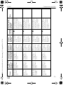
BMW 3 series
E36, constr.
year: 93–…
with alarm
Blue/green,
cable strand left
on the sill
Blue/brown,
cable strand left
on the sill
Pin 25, white
26-pin plug for
the CL control
unit
Pin 19, white
26-pin plug for
the CL control
unit
fig. 9 Brown/grey/yellow,
on the door contact
front left on the B
pillar, door contact is
negatively charged
A contact pin from
BMW with the part
no. 61131393704
may be required, CL
control unit is behind
the glove
compartment
BMW 5 series
E34, constr.
year: 88–95
Blue/green,
cable strand left
on the sill
Blue/brown,
cable strand left
on the sill
Pin 16, yellow
26-pin plug for
the CL control
unit
Pin 7, yellow
26-pin plug for
the CL control
unit
fig. 9 Brown/violet, on the
door contact left on
the B pillar
A contact pin from
BMW with the part
no. 61131393704
may be required, CL
control unit is behind
the rear seat
BMW 5 series
E34, constr.
year: 88–95
Blue/green,
cable strand left
on the sill
Blue/brown,
cable strand left
on the sill
(until 9/91) Pin 2
or 6, white
26-pin plug from
CL control unit
(from 9/91)
Pin 25, white
26-pin plug for
the CL control
unit
(until 9/91) Pin 1,
white 26-pin
plug for the CL
control unit
(from 9/91)
Pin 24, white
26-pin plug for
the CL control
unit
fig. 9 Brown/violet, on the
door contact front left
on the B pillar, door
contact is negatively
charged
A contact pin from
BMW with the part
no. 61131393704
may be required, CL
control unit is behind
the rear seat
Mercedes
190 W201,
constr. year:
…–94
Black/white,
cable strand left
on the sill
Black/green,
cable strand left
on the sill
Blue, A pillar left,
coming out of
the driver's door
Blue, A pillar left,
coming out of
the driver's door
fig. b Brown/white, on the
door contact front left
on the A pillar, door
contact is negatively
charged
connect the blue/red
control cable in the
direction of the door
and the grey/yellow
cable in the direction
of the CL-pump
Vehicle
Indicator left,
cable colour,
position
Indicator
right, cable
colour,
position
CL open, cable
colour,
position
CL closed,
cable colour,
position
Circuit
diagram
Door contact, cable
colour, position
Remarks
MT400--IO--16s.book Seite 12 Donnerstag, 25. August 2016 2:37 14

MT400 Connecting MT400
EN
13
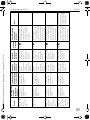
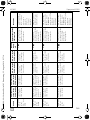
Mercedes
200 W124,
constr. year:
…–95
Black/white,
cable strand left
on the sill
Black/green,
cable strand left
on the sill
Blue, A pillar left,
coming out of
the driver's door
Blue, A pillar left,
coming out of
the driver's door
fig. b Brown/white, on the
door contact front left
on the A pillar, door
contact is negatively
charged
connect the blue/red
control cable in the
direction of the door
and the grey/yellow
cable in the direction
of the CL-pump
Mercedes
C180 W202,
constr. year:
94–…
Black/white,
cable strand left
on the sill
Black/green,
cable strand left
on the sill
Blue, A pillar left,
coming out of
the driver's door
Black, A pillar
left, coming out
of the driver's
door
fig. 0 Brown/white, on the
door contact front left
on the B pillar, door
contact is negatively
charged
Opel Astra F
and G,
constr. year:
92–…
Black/white,
cable strand left
on the sill
Black/green,
cable strand left
on the sill
Brown/white,
A pillar left,
coming out of
the driver's door
Brown/red, A
pillar left, coming
out of the driver's
door
fig. 0 Brown/white, on the
door contact front left
on the A pillar, door
contact is negatively
charged
Opel Calibra,
constr. year:
90–…
Black/white,
cable strand left
on the sill
Black/green,
cable strand left
on the sill
Brown/white,
A pillar left,
coming out of
the driver's door
Brown/red, A
pillar left, coming
out of the driver's
door
fig. 0 Grey, on the door
contact front left on
the A pillar, door
contact is negatively
charged
Opel Corsa
A, B, constr.
year:
93–2000
Black/white,
cable strand left
on the sill
Black/green,
cable strand left
on the sill
Brown/white,
A pillar left,
coming out of
the driver's door
Brown/red, A
pillar left, coming
out of the driver's
door
fig. 0 Grey, on the door
contact front left on
the A pillar, door
contact is negatively
charged
Vehicle
Indicator left,
cable colour,
position
Indicator
right, cable
colour,
position
CL open, cable
colour,
position
CL closed,
cable colour,
position
Circuit
diagram
Door contact, cable
colour, position
Remarks
MT400--IO--16s.book Seite 13 Donnerstag, 25. August 2016 2:37 14

Connecting MT400 MT400
EN
14
Opel Kadett
E, constr.
year: 90–…
Black/white,
cable strand left
on the sill
Black/green,
cable strand left
on the sill
Brown/white,
A pillar left,
coming out of
the driver's door
Brown/red, A
pillar left, coming
out of the driver's
door
fig. 0 Green, on the door
contact front left on
the A pillar, door
contact is negatively
charged
Opel Omega
A and B,
constr. year:
90–…
Black/white,
cable strand left
on the sill
Black/green,
cable strand left
on the sill
Brown/white,
A pillar left,
coming out of
the driver's door
Brown/red, A
pillar left, coming
out of the driver's
door
fig. 0 Grey, on the door
contact front left on
the A pillar, door
contact is negatively
charged
Opel Vectra A
and B
Black/white,
cable strand left
on the sill
Black/green,
cable strand left
on the sill
Brown/white,
A pillar left,
coming out of
the driver's door
Brown/red, A
pillar left, coming
out of the driver's
door
fig. 0 Grey/white or
brown/white, on the
door contact front left
on the A pillar, door
contact is negatively
charged
VW Golf lll
and Vento
type 1HXO,
constr. year:
91–…
Black/white,
cable strand left
on the sill
Black/green,
cable strand left
on the sill
Green, A pillar
left, coming out
of the driver's
door
Grey, A pillar left,
coming out of
the driver's door
fig. 9 Brown/white, on the
door contact front left
on the A pillar, door
contact is negatively
charged
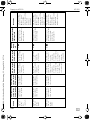
VW Golf lV,
constr. year:
97–… with
electric
windows
Black/white,
cable strand left
on the sill
Black/green,
cable strand left
on the sill
Yellow/green pin
24, on the door
control unit,
driver's side
Yellow/blue pin
4, on the door
control unit,
driver's side
fig. 0 Brown/white, on the
door contact front left
on the A pillar, door
contact is negatively
charged
The door control unit
is on the window
regulator underneath
the door panel
Vehicle
Indicator left,
cable colour,
position
Indicator
right, cable
colour,
position
CL open, cable
colour,
position
CL closed,
cable colour,
position
Circuit
diagram
Door contact, cable
colour, position
Remarks
MT400--IO--16s.book Seite 14 Donnerstag, 25. August 2016 2:37 14

MT400 Connecting MT400
EN
15
VW Golf lV.
constr. year:
97 –…
without
electric
windows
Black/white,
cable strand left
on the sill
Black/green,
cable strand left
on the sill
Yellow/green,
CL control unit
grey 24 pin plug
underneath the
dashboard
Yellow/blue or
blue, CL control
unit grey 24 pin
plug underneath
the dashboard
fig. 0 Blue/grey, on the CL
control unit on pin 18,
door contact is
negatively charged
CL control unit is on
the left, next to the
steering column; the
cable colours can also
be found on the A
pillar
VW Lupo,
constr. year:
98–…
Black/white,
cable strand left
on the sill
Black/green,
cable strand left
on the sill
Blue/violet,
A pillar left,
coming out of
the driver's door
Grey/yellow, A
pillar left, coming
out of the driver's
door
fig. 0 Brown/white, in the
cable duct of the A
pillar, door contact is
negatively charged
VW Passat
35i, constr.
year: 88–92
Black/white,
cable strand left
on the sill
Black/green,
cable strand left
on the sill
Black/white,
A pillar left,
coming out of
the driver's door
Red/yellow, A
pillar left, coming
out of the driver's
door
fig. 9 Brown/white, on the
door contact front left
on the A pillar, door
contact is negatively
charged
VW Passat
35i, constr.
year: 93–96
Black/white,
cable strand left
on the sill
Black/green,
cable strand left
on the sill
Green, A pillar
left, coming out
of the driver's
door
Grey, A pillar left,
coming out of
the driver's door
fig. 9 Brown/white, on the
door contact front left
on the A pillar, door
contact is negatively
charged
VW Passat
3B, constr.
year:
9/97–…
Black/white,
cable strand left
on the sill
Black/green,
cable strand left
on the sill
Red/blue, pin 4
from the original
CL control unit
Brown/blue, pin
2 from the
original CL
control unit
fig. 0 Brown/white, in the
cable duct of the A
pillar, door contact is
negatively charged
Central locking is
earth controlled. A
200 Ω resistor must
be inserted in the
blue/red cable, CL
control unit is in a
black box in the
driver's feet area
under the carpet
Vehicle
Indicator left,
cable colour,
position
Indicator
right, cable
colour,
position
CL open, cable
colour,
position
CL closed,
cable colour,
position
Circuit
diagram
Door contact, cable
colour, position
Remarks
MT400--IO--16s.book Seite 15 Donnerstag, 25. August 2016 2:37 14

Connecting MT400 MT400
EN
16
VW Polo 6N,
constr. year:
95–…
Black/white,
cable strand left
on the sill
Black/green,
cable strand left
on the sill
Grey/black,
A pillar left,
coming out of
the driver's door
Grey/red, A pillar
left, coming out
of the driver's
door
fig. 9 Brown/white, on the
door contact front left
on the A pillar, door
contact is negatively
charged
VW Sharan
7M, constr.
year: 96–…
Black/white,
cable strand left
on the sill
Black/green,
cable strand left
on the sill
Green, A pillar
left, coming out
of the driver's
door
Grey, A pillar left,
coming out of
the driver's door
fig. 9 Brown/white, in the
cable duct of the A
pillar, door contact is
negatively charged
VW T4,
constr. year:
93–…
Black/white,
cable strand left
on the sill
Black/green,
cable strand left
on the sill
Yellow, A pillar
left, coming out
of the driver's
door
White, A pillar
left, coming out
of the driver's
door
fig. 9 Brown/white, behind
the fuse box, door
contact is negatively
charged
Vehicle
Indicator left,
cable colour,
position
Indicator
right, cable
colour,
position
CL open, cable
colour,
position
CL closed,
cable colour,
position
Circuit
diagram
Door contact, cable
colour, position
Remarks
MT400--IO--16s.book Seite 16 Donnerstag, 25. August 2016 2:37 14

MT400 Programming MagicTouch
EN
17
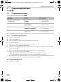
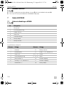
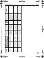
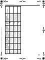
8 Programming MagicTouch
See fig. e
8.1 Programmable functions
The standard settings are printed in bold.
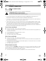
8.2 Programming functions
➤ Open the vehicle door.
➤ Switch on the ignition.
➤ Press and hold the “Open” button and switch the ignition off.
➤ Let go of the button.
✓ The status LED and the hazard lights are lit continually.
✓ The system is now in programming mode.
➤ Select the corresponding setting in accordance with the table, see chapter “Programmable
functions” on page 17.
✓ The status LED and the hazard lights go out while the value is being saved.
✓ After 2 sec. you will receive a confirmation:
– After pressing the “Close” button: status LED and hazard lights flash once.
– After pressing the “Open” button: status LED and hazard lights flash twice.
✓ When the status LED and hazard lights are lit continually, the function has been programmed.
You can now program other functions or exit programming mode.
To exit programming mode:
➤ Switch on the ignition.
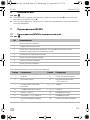
Function Values Press button
Activation time for central
locking system
3sec.
0.7 sec.
1 x “Close” button
1 x “Open” button
Convenience function activated
deactivated
2 x “Close” button
2 x “Open” button
Control for door contact switch positive connection
negative connection
3 x “Close” button
3 x “Open” button
Control for hazard lights system activated
deactivated
4 x “Close” button
4 x “Open” button
MT400--IO--16s.book Seite 17 Donnerstag, 25. August 2016 2:37 14

Operating MagicTouch MT400
EN
18
9 Operating MagicTouch
9.1 Using the remote control
See fig. f
Observe the following instructions when you use MagicTouch:
!
• To ensure the remote control functions properly, a disturbance-free connection between the
hand-held transmitter and the control unit is required.
• Depending on where the control unit is installed, and the transmission power of nearby sources
of interference, the range is up to 20 m.
• Each time the hand-held transmitter is used, it sends a new code (rolling code). For this reason,
the control unit might not recognise the hand-held transmitter immediately if you use the
hand-held transmitter too frequently without the control unit receiving the transmission signal.
In this event, press the hand-held transmitter again another one to three times; after the third
attempt at the latest, the control unit will detect the hand-held transmitter again.
To close the central locking:
➤ Press the “Close” button on the hand-held transmitter.
✓ If the ignition is switched off, the hazard light flashes once for confirmation.
✓ When set: the convenience function is activated.
✓ The interior light is switched off.
✓ The status LED starts flashing.
To open the central locking:
➤ Press the “Open” button on the hand-held transmitter.
✓ If the ignition is switched off, the hazard light flashes twice for confirmation.
✓ In vehicles with a negatively connected door contact: the interior lighting is switched on and
goes out again when the ignition is switched on.
✓ The status LED goes out.
Using the convenience function
If the vehicle is locked, pressing the middle button on the hand-held transmitter activates the
convenience output. Depending on the setting, the convenience output is connected when the
central locking is closed, or by pressing the “Comfort” button.
✓ The hazard lights flash once for confirmation.
CAUTION! Danger of crushing!
Never allow the electric windows to be closed while they are unattended.
MT400--IO--16s.book Seite 18 Donnerstag, 25. August 2016 2:37 14
La pagina si sta caricando...
La pagina si sta caricando...
La pagina si sta caricando...
La pagina si sta caricando...
La pagina si sta caricando...
La pagina si sta caricando...
La pagina si sta caricando...
La pagina si sta caricando...
La pagina si sta caricando...
La pagina si sta caricando...
La pagina si sta caricando...
La pagina si sta caricando...
La pagina si sta caricando...
La pagina si sta caricando...
La pagina si sta caricando...
La pagina si sta caricando...
La pagina si sta caricando...
La pagina si sta caricando...
La pagina si sta caricando...
La pagina si sta caricando...
La pagina si sta caricando...
La pagina si sta caricando...
La pagina si sta caricando...
La pagina si sta caricando...
La pagina si sta caricando...
La pagina si sta caricando...
La pagina si sta caricando...
La pagina si sta caricando...
La pagina si sta caricando...
La pagina si sta caricando...
La pagina si sta caricando...
La pagina si sta caricando...
La pagina si sta caricando...
La pagina si sta caricando...
La pagina si sta caricando...
La pagina si sta caricando...
La pagina si sta caricando...
La pagina si sta caricando...
La pagina si sta caricando...
La pagina si sta caricando...
La pagina si sta caricando...
La pagina si sta caricando...
La pagina si sta caricando...
La pagina si sta caricando...
La pagina si sta caricando...
La pagina si sta caricando...
La pagina si sta caricando...
La pagina si sta caricando...
La pagina si sta caricando...
La pagina si sta caricando...
La pagina si sta caricando...
La pagina si sta caricando...
La pagina si sta caricando...
La pagina si sta caricando...
La pagina si sta caricando...
La pagina si sta caricando...
La pagina si sta caricando...
La pagina si sta caricando...
La pagina si sta caricando...
La pagina si sta caricando...
La pagina si sta caricando...
La pagina si sta caricando...
La pagina si sta caricando...
La pagina si sta caricando...
La pagina si sta caricando...
La pagina si sta caricando...
La pagina si sta caricando...
La pagina si sta caricando...
La pagina si sta caricando...
La pagina si sta caricando...
La pagina si sta caricando...
La pagina si sta caricando...
La pagina si sta caricando...
La pagina si sta caricando...
La pagina si sta caricando...
La pagina si sta caricando...
La pagina si sta caricando...
La pagina si sta caricando...
La pagina si sta caricando...
La pagina si sta caricando...
La pagina si sta caricando...
La pagina si sta caricando...
La pagina si sta caricando...
La pagina si sta caricando...
La pagina si sta caricando...
La pagina si sta caricando...
La pagina si sta caricando...
La pagina si sta caricando...
La pagina si sta caricando...
La pagina si sta caricando...
La pagina si sta caricando...
La pagina si sta caricando...
La pagina si sta caricando...
La pagina si sta caricando...
La pagina si sta caricando...
La pagina si sta caricando...
La pagina si sta caricando...
La pagina si sta caricando...
La pagina si sta caricando...
La pagina si sta caricando...
La pagina si sta caricando...
La pagina si sta caricando...
La pagina si sta caricando...
La pagina si sta caricando...
La pagina si sta caricando...
La pagina si sta caricando...
La pagina si sta caricando...
La pagina si sta caricando...
La pagina si sta caricando...
La pagina si sta caricando...
La pagina si sta caricando...
La pagina si sta caricando...
La pagina si sta caricando...
La pagina si sta caricando...
La pagina si sta caricando...
La pagina si sta caricando...
La pagina si sta caricando...
La pagina si sta caricando...
La pagina si sta caricando...
La pagina si sta caricando...
La pagina si sta caricando...
La pagina si sta caricando...
La pagina si sta caricando...
La pagina si sta caricando...
La pagina si sta caricando...
La pagina si sta caricando...
La pagina si sta caricando...
La pagina si sta caricando...
La pagina si sta caricando...
La pagina si sta caricando...
La pagina si sta caricando...
La pagina si sta caricando...
La pagina si sta caricando...
La pagina si sta caricando...
La pagina si sta caricando...
La pagina si sta caricando...
La pagina si sta caricando...
La pagina si sta caricando...
La pagina si sta caricando...
La pagina si sta caricando...
La pagina si sta caricando...
La pagina si sta caricando...
La pagina si sta caricando...
La pagina si sta caricando...
La pagina si sta caricando...
La pagina si sta caricando...
La pagina si sta caricando...
La pagina si sta caricando...
La pagina si sta caricando...
La pagina si sta caricando...
La pagina si sta caricando...
La pagina si sta caricando...
La pagina si sta caricando...
La pagina si sta caricando...
La pagina si sta caricando...
La pagina si sta caricando...
La pagina si sta caricando...
La pagina si sta caricando...
La pagina si sta caricando...
La pagina si sta caricando...
La pagina si sta caricando...
La pagina si sta caricando...
La pagina si sta caricando...
La pagina si sta caricando...
La pagina si sta caricando...
La pagina si sta caricando...
La pagina si sta caricando...
La pagina si sta caricando...
La pagina si sta caricando...
La pagina si sta caricando...
La pagina si sta caricando...
La pagina si sta caricando...
La pagina si sta caricando...
La pagina si sta caricando...
La pagina si sta caricando...
La pagina si sta caricando...
La pagina si sta caricando...
La pagina si sta caricando...
La pagina si sta caricando...
La pagina si sta caricando...
La pagina si sta caricando...
La pagina si sta caricando...
La pagina si sta caricando...
La pagina si sta caricando...
La pagina si sta caricando...
La pagina si sta caricando...
La pagina si sta caricando...
La pagina si sta caricando...
La pagina si sta caricando...
La pagina si sta caricando...
La pagina si sta caricando...
La pagina si sta caricando...
La pagina si sta caricando...
La pagina si sta caricando...
La pagina si sta caricando...
La pagina si sta caricando...
La pagina si sta caricando...
La pagina si sta caricando...
La pagina si sta caricando...
La pagina si sta caricando...
La pagina si sta caricando...
La pagina si sta caricando...
La pagina si sta caricando...
La pagina si sta caricando...
La pagina si sta caricando...
La pagina si sta caricando...
La pagina si sta caricando...
La pagina si sta caricando...
La pagina si sta caricando...
La pagina si sta caricando...
La pagina si sta caricando...
La pagina si sta caricando...
La pagina si sta caricando...
La pagina si sta caricando...
La pagina si sta caricando...
La pagina si sta caricando...
La pagina si sta caricando...
La pagina si sta caricando...
La pagina si sta caricando...
La pagina si sta caricando...
La pagina si sta caricando...
La pagina si sta caricando...
La pagina si sta caricando...
La pagina si sta caricando...
La pagina si sta caricando...
La pagina si sta caricando...
La pagina si sta caricando...
La pagina si sta caricando...
La pagina si sta caricando...
La pagina si sta caricando...
La pagina si sta caricando...
La pagina si sta caricando...
La pagina si sta caricando...
La pagina si sta caricando...
La pagina si sta caricando...
La pagina si sta caricando...
La pagina si sta caricando...
La pagina si sta caricando...
La pagina si sta caricando...
La pagina si sta caricando...
La pagina si sta caricando...
La pagina si sta caricando...
La pagina si sta caricando...
La pagina si sta caricando...
La pagina si sta caricando...
La pagina si sta caricando...
La pagina si sta caricando...
La pagina si sta caricando...
La pagina si sta caricando...
La pagina si sta caricando...
La pagina si sta caricando...
La pagina si sta caricando...
La pagina si sta caricando...
La pagina si sta caricando...
La pagina si sta caricando...
La pagina si sta caricando...
La pagina si sta caricando...
La pagina si sta caricando...
La pagina si sta caricando...
La pagina si sta caricando...
La pagina si sta caricando...
La pagina si sta caricando...
La pagina si sta caricando...
La pagina si sta caricando...
La pagina si sta caricando...
La pagina si sta caricando...
La pagina si sta caricando...
La pagina si sta caricando...
La pagina si sta caricando...
La pagina si sta caricando...
La pagina si sta caricando...
La pagina si sta caricando...
La pagina si sta caricando...
La pagina si sta caricando...
La pagina si sta caricando...
La pagina si sta caricando...
La pagina si sta caricando...
La pagina si sta caricando...
La pagina si sta caricando...
La pagina si sta caricando...
La pagina si sta caricando...
La pagina si sta caricando...
La pagina si sta caricando...
La pagina si sta caricando...
La pagina si sta caricando...
La pagina si sta caricando...
La pagina si sta caricando...
La pagina si sta caricando...
La pagina si sta caricando...
La pagina si sta caricando...
La pagina si sta caricando...
La pagina si sta caricando...
La pagina si sta caricando...
La pagina si sta caricando...
La pagina si sta caricando...
La pagina si sta caricando...
La pagina si sta caricando...
La pagina si sta caricando...
La pagina si sta caricando...
La pagina si sta caricando...
La pagina si sta caricando...
La pagina si sta caricando...
La pagina si sta caricando...
La pagina si sta caricando...
La pagina si sta caricando...
La pagina si sta caricando...
La pagina si sta caricando...
La pagina si sta caricando...
La pagina si sta caricando...
La pagina si sta caricando...
La pagina si sta caricando...
La pagina si sta caricando...
La pagina si sta caricando...
La pagina si sta caricando...
La pagina si sta caricando...
La pagina si sta caricando...
La pagina si sta caricando...
La pagina si sta caricando...
-
 1
1
-
 2
2
-
 3
3
-
 4
4
-
 5
5
-
 6
6
-
 7
7
-
 8
8
-
 9
9
-
 10
10
-
 11
11
-
 12
12
-
 13
13
-
 14
14
-
 15
15
-
 16
16
-
 17
17
-
 18
18
-
 19
19
-
 20
20
-
 21
21
-
 22
22
-
 23
23
-
 24
24
-
 25
25
-
 26
26
-
 27
27
-
 28
28
-
 29
29
-
 30
30
-
 31
31
-
 32
32
-
 33
33
-
 34
34
-
 35
35
-
 36
36
-
 37
37
-
 38
38
-
 39
39
-
 40
40
-
 41
41
-
 42
42
-
 43
43
-
 44
44
-
 45
45
-
 46
46
-
 47
47
-
 48
48
-
 49
49
-
 50
50
-
 51
51
-
 52
52
-
 53
53
-
 54
54
-
 55
55
-
 56
56
-
 57
57
-
 58
58
-
 59
59
-
 60
60
-
 61
61
-
 62
62
-
 63
63
-
 64
64
-
 65
65
-
 66
66
-
 67
67
-
 68
68
-
 69
69
-
 70
70
-
 71
71
-
 72
72
-
 73
73
-
 74
74
-
 75
75
-
 76
76
-
 77
77
-
 78
78
-
 79
79
-
 80
80
-
 81
81
-
 82
82
-
 83
83
-
 84
84
-
 85
85
-
 86
86
-
 87
87
-
 88
88
-
 89
89
-
 90
90
-
 91
91
-
 92
92
-
 93
93
-
 94
94
-
 95
95
-
 96
96
-
 97
97
-
 98
98
-
 99
99
-
 100
100
-
 101
101
-
 102
102
-
 103
103
-
 104
104
-
 105
105
-
 106
106
-
 107
107
-
 108
108
-
 109
109
-
 110
110
-
 111
111
-
 112
112
-
 113
113
-
 114
114
-
 115
115
-
 116
116
-
 117
117
-
 118
118
-
 119
119
-
 120
120
-
 121
121
-
 122
122
-
 123
123
-
 124
124
-
 125
125
-
 126
126
-
 127
127
-
 128
128
-
 129
129
-
 130
130
-
 131
131
-
 132
132
-
 133
133
-
 134
134
-
 135
135
-
 136
136
-
 137
137
-
 138
138
-
 139
139
-
 140
140
-
 141
141
-
 142
142
-
 143
143
-
 144
144
-
 145
145
-
 146
146
-
 147
147
-
 148
148
-
 149
149
-
 150
150
-
 151
151
-
 152
152
-
 153
153
-
 154
154
-
 155
155
-
 156
156
-
 157
157
-
 158
158
-
 159
159
-
 160
160
-
 161
161
-
 162
162
-
 163
163
-
 164
164
-
 165
165
-
 166
166
-
 167
167
-
 168
168
-
 169
169
-
 170
170
-
 171
171
-
 172
172
-
 173
173
-
 174
174
-
 175
175
-
 176
176
-
 177
177
-
 178
178
-
 179
179
-
 180
180
-
 181
181
-
 182
182
-
 183
183
-
 184
184
-
 185
185
-
 186
186
-
 187
187
-
 188
188
-
 189
189
-
 190
190
-
 191
191
-
 192
192
-
 193
193
-
 194
194
-
 195
195
-
 196
196
-
 197
197
-
 198
198
-
 199
199
-
 200
200
-
 201
201
-
 202
202
-
 203
203
-
 204
204
-
 205
205
-
 206
206
-
 207
207
-
 208
208
-
 209
209
-
 210
210
-
 211
211
-
 212
212
-
 213
213
-
 214
214
-
 215
215
-
 216
216
-
 217
217
-
 218
218
-
 219
219
-
 220
220
-
 221
221
-
 222
222
-
 223
223
-
 224
224
-
 225
225
-
 226
226
-
 227
227
-
 228
228
-
 229
229
-
 230
230
-
 231
231
-
 232
232
-
 233
233
-
 234
234
-
 235
235
-
 236
236
-
 237
237
-
 238
238
-
 239
239
-
 240
240
-
 241
241
-
 242
242
-
 243
243
-
 244
244
-
 245
245
-
 246
246
-
 247
247
-
 248
248
-
 249
249
-
 250
250
-
 251
251
-
 252
252
-
 253
253
-
 254
254
-
 255
255
-
 256
256
-
 257
257
-
 258
258
-
 259
259
-
 260
260
-
 261
261
-
 262
262
-
 263
263
-
 264
264
-
 265
265
-
 266
266
-
 267
267
-
 268
268
-
 269
269
-
 270
270
-
 271
271
-
 272
272
-
 273
273
-
 274
274
-
 275
275
-
 276
276
-
 277
277
-
 278
278
-
 279
279
-
 280
280
-
 281
281
-
 282
282
-
 283
283
-
 284
284
-
 285
285
-
 286
286
-
 287
287
-
 288
288
-
 289
289
-
 290
290
-
 291
291
-
 292
292
-
 293
293
-
 294
294
-
 295
295
-
 296
296
-
 297
297
-
 298
298
-
 299
299
-
 300
300
-
 301
301
-
 302
302
-
 303
303
-
 304
304
-
 305
305
-
 306
306
-
 307
307
-
 308
308
-
 309
309
-
 310
310
-
 311
311
-
 312
312
-
 313
313
-
 314
314
-
 315
315
-
 316
316
-
 317
317
-
 318
318
-
 319
319
-
 320
320
-
 321
321
-
 322
322
-
 323
323
-
 324
324
-
 325
325
-
 326
326
-
 327
327
-
 328
328
-
 329
329
-
 330
330
-
 331
331
-
 332
332
-
 333
333
-
 334
334
-
 335
335
-
 336
336
-
 337
337
-
 338
338


Dometic MagicTouch MT400 Istruzioni per l'uso
- Tipo
- Istruzioni per l'uso
in altre lingue
Documenti correlati
-
Waeco TFL100 Istruzioni per l'uso
-
-
Dometic VT100WiFi Istruzioni per l'uso
-
Waeco MagicTouch MT100 Istruzioni per l'uso
-
-
-
-
-
-
Altri documenti
-
-
-
Chamberlain LiftMaster 54332E Manuale del proprietario
-
Velleman WSG152 Manuale utente
-
Velleman WSL213 Assembly Manual
-
Sommer 4020 Classic Manuale del proprietario
-
Velleman WSL125 Manuale utente
-
BMW 2000 525d Supplementary Owner's Handbook
-
Velleman WSSA122 Manuale utente
-
Velleman WSAH134 Manuale utente