
Documentazione
Tecnica
S45
rev. 2.2
07/2002
©
CAME
CANCELLI
AUTOMATICI
FROG A
CANCELLI AUTOMATICI
SCHEDA COMANDO
CONTROL BOARD
CARTE DE COMMANDE
STEUERPLATINE
TARJETA DE MANDO
ITALIANO/ ENGLISH/ ESPAÑOL
119AS45-1
SERIE FROG |
FROG SERIES
|
SERIE FROG
8
6
5
2
4
7
10
9
3
1
9
1
10
3
4x1,5
3x1,5
230V
4x1
2x1,5
RG58
3x1
5x1
2x1
4x1
RX
TX
RX
TX
4x1,5
2x1
11
10
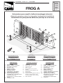
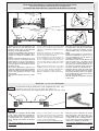
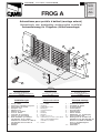
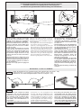
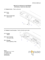
1 - Gruppo FROG
2 - Quadro comando incorporato
3 - Fotocellule di sicurezza
4 - Ricevitore radio
5 - Selettore a chiave
6 - Antenna di ricezione
7 - Pulsantiera interna
8 - Lampeggiatore di movimento
9 - Colonnina per fotocellula
10 - Scatola di derivazione per cavo
motoriduttore (é consigliabile fare le
connessioni del cavo
motoriduttore in scatole di deriva-
zione)
11 - Trasmettitore radio
Impianto tipo Instalación tipo
1 - Conjunto FROG
2 - Cuadro de mando incorporado
3 - Fotocélulas de seguridad
4 - Radiorreceptor
5 - Selector mediante llave
6 - Antena receptora
7 - Pulsadores de interior
8 - Lámpara intermitente de movimento
9 - Columna para fotocélula
10 - Caja de paso para el cable del
motorreductor (se aconseja hacer las
conexiones del cable del
motorreductor en cajas de paso)
11 - Transmisor
Standard installation
1 - FROG unit
2 - Control panel (incorporated)
3 - Safety photocells
4 - Radio receveir
5 - Key-operated selector switch
6 - Antenna
7 - Internally located pushbutton arry
8 - Flashing light
9 - Photocell column
10 - Connector block for gearmotor cable (it is
advisable to make gearmotor cable
connections within connector blocks).
11 - Radio transmitter
Automazione per cancelli a battente (montaggio interrato)
Automatic opening system for wing gates (underground installation)
Automatizacion para puertas batientes (montaje en el terreno)
Cables de alimentación motores:
2 x 1.5 mm
2
hasta 20 m
2 x 2.5 " " 30 m
Cables de conexión microinterruptores:
3 x 1mm
2
Power wires to motor:
2 x 1.5 mm
2
up to 20 m
2 x 2.5 mm
2
up to 30 m
Wiring for microswitches:
3 x 1 mm
2
Cavi di alimentazione motori:
2 x 1.5 mm
2
fino a 20 m
2 x 2.5 mm
2
fino a 30 m
Cavi di collegamento microinterruttori:
3 x 1 mm
2
FROG A24

-2-
ITALIANO • ENGLISH • ESPAÑOL
Attenzione! Controllate che le apparecchiature di comando, di sicurez-
za e gli accessori siano originali CAME; ciò garantisce e rende l'impianto
di facile esecuzione e manutenzione.
Description:
- Swing gate automation for in-ground mounting in foundation casing
(FROG-B / FROG-BI);
- Designed and constructed entirely by CAME Cancelli Automatici S.p.a
- IP67 protecting rating;
- Guaranteed for 24 months, unless tampered with by unauthorized
personnel.
Versions:
Single-phase motor 230V a.c. / 200 W, with built-in ther-
mal cut-out;
Single-phase motor 230V a.c. / 300 W, with built-in ther-
mal cut-out;
Single-phase motor 24V d.c. / 180 W, with permanent
magnets .
Release mechanism:
Mechanical release device with lever key;
Mechanical release device with three-sided key;
Mechanical release device with EURO DIN cylinder.
Accessories:
Transmission lever for aperture up to 140° (max. 2 m.
each wing);
Device for wing aperture in excess of 140°; this device
can also be used for special passages with 360° aperture (max. 2 m.
each wing). It cannot be used with the FROG A24 model;
Single-cylinder electric lock;
Double-cylinder electric lock.
Operational limits:
- Door height up to 3,5 meters
- Maximum standard opening of wing: 110°;
Attention! to ensure easy installation and conformance with current
safety norms, we raccomend installation of CAME safety and control
accessories.
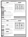
General specifications
Caratteristiche generali
Descrizione:
- Automazione per cancelli a battente per montaggio interrato in cassa
di fondazione (FROG-B / FROG-BI);
- Progettato e costruito interamente dalla CAME Cancelli Automatici
S.p.a.
- Grado di protezione IP 67;
- Garantito 24 mesi salvo manomissioni.
Versioni:
Motore monofase 230V a.c. / 200 W, con protettore
termico incorporato;
Motore monofase 230V a.c. / 300 W, con protettore
termico incorporato;
Motore monofase 24V d.c. / 180 W, a magneti perma-
nenti.
Meccanismi di sblocco:
Sblocco meccanico con chiave a leva;
Sblocco meccanico con chiave trilobata;
Sblocco meccanico con cilindro EURO DIN.
Accessori:
Leva di trasmissione per aperture dell’anta fino a 140°
(max. 2 m. per anta);
Dispositivo per l’apertura dell’anta fino a 180°; questo
dispositivo permette anche passaggi speciali con aperture a 360°
(max. 2 m. per anta). Non si puo’ utilizzare con la versione
FROG A24;
Elettroserratura di blocco a cilindro singolo;
Elettroserratura di blocco a cilindro doppio.
Limiti d'impiego:
- Dimensione ante fino a 3,5 metri
- Apertura standard dell’anta: max 110°;
FROG A24
FROG AV
A4364
A4365
A4366
A4370
FL180
LOCK 81
LOCK 82
A4364
A4365
A4366
A4370
FL180
LOCK 81
LOCK 82
FROG A24
FROG AV
FROG A
ITALIANO
FROG A
ENGLISH
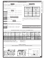
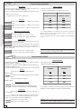
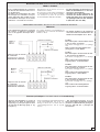
- I valori indicati sono validi per un servizio ad uso residenziale; per un
servizio intensivo ridurre tali valori dal 10 al 20%.
* É consigliabile prevedere una serratura elettrica qualora l’anta superi
i 2,5 m
- The values shown refer to normal residential use; for more intensive
use, these values should be reduced by 10 to 20%.
* An eletric lock is suggested when the gate wing is wider than 2,5 m
Larghezza anta
m
Peso anta
Kg
2.00 800
2.50 600
*3.50 400
Width of gate wing
m.
Weight of gate wing
Kg.
2.00 800
2.50 600
*
3.50
400

-3-
ITALIANO • ENGLISH • ESPAÑOL
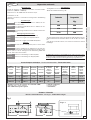
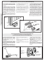
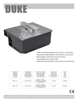
Fig. 1
Fig. 1-1
405 330
160
60
Descripción:
- Automatización para verjas de batiente con montje enterrado en caja
de cimentación (FROG-B / FROG-BI);
- Diseñado y fabricado enteramente por CAME Cancelli Automatici
S.p.a
- Grado de protección IP67;
- Garantizado 24 meses, salvo manipulaciones.
Modelos:
Motor monofásico 230V a.c. / 200 W, con protector tér-
mico incorporado;
Motor monofásico 230V a.c. / 300 W, con protector tér-
mico incorporado;
Motor monofásico 24V d.c. / 180 W, con imanes perma-
nentes.
Mecanismos de desbloqueo:
Desbloqueo mecánico con llave de palanca;
Desbloqueo mecánico con llave trilobulada;
Desbloqueo mecánico con cilindro EURO DIN.
Accesorios:
Palanca de transmisión para l’apertura hasta 140° (máx. 2 m por
cada hoja);
Dispositivo para apertura de la puerta hasta 180°.
Este dispositivo consiente también unos pasos especiales con aper-
tura de 360° (máx. 2 m. por cada hoja). Con el modelo FROG A24 no
se puede utilizarlo;
Electrocerradura de bloqueo con cilindro simple;
Electrocerradura de bloqueo con cilindro doble.
Limites de empleo:
- Dimensión hojas hasta 3,5 metros
- Apertura standard máxima de la hoja: 110°;
Atención! Comprobar que los equipos de mando, de seguridad y los
acesorios sean originales CAME; lo cual garantiza y facilita el uso y el
mantenimiento del aparato.
Características Generales
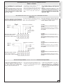
* Regolabile mediante quadri comando CAME **Servizio intensivo;
* Can be adjusted using CAME control panels **Heavy duty;
* Ajustable mediante los cuadros de mando CAME ** Servicio intensivo.
Caratteristiche tecniche -
Technical features
- Descripción técnica
FROG A24
FROG AV
FROG A
A4364
A4365
A4366
A4370
FL180
LOCK 81
LOCK 82
FROG-B / FROG-BI
Misure di ingombro -
External dimensions
- Dimensiones máximas
ESPAÑOL
- Los valores indicados valen para el uso residencial; para un servicio
más intensivo es preciso reducir dichos valores de 10 al 20%.
* Es aconsejable proveer una cerradura eléctrica si hoia supera los
2,5 m.
Ancho hoja
m.
Peso hoja
K
g
.
2.00 800
2.50 600
*
3.50
400
MOTO-
RIDUTTORE
PESO ALIMENTAZIONE ASSORBIMENTO POTENZA
INTERMITTENZA
LAVORO
COPPIA MAX
RAPPORTO DI
RIDUZIONE
TEMPO
CORSA
CONDEN-
SATORE
GEARMOTOR WEIGHT POWER SUPPLY CURRENT POWER DUTY CICLE MAX TORQUE
REDUCTION
RATIO
TRAVEL
TIME
CAPACITOR
MOTOR-
REDUCTOR
PESO ALIMENTACION ABSORBENCIA POTENCIA
INTERMITENCIA
TRABAJO
PAREJA MAX
(MOTOR)
RELACION DE
REDUCCION
TIEMPO DE
RECORRIDO
CONDEN-
SADOR
FROG A 11 Kg 230V a.c. 1,9 A 200 W 30 %
* 320 Nm
1/1152
18 s 16 µF
FROG A24 11,5 Kg 24V d.c. 15 A max 180 W ** 16÷45 s -
FROG AV 11 Kg 230V a.c 2,5 A 300 W 30 %
* 240 Nm
9 s 20 µF

-4-
ITALIANO • ENGLISH • ESPAÑOL
67
67
160
100 60
3
Fig. 2
Fig.3
67
2
5
7
1
6
4
3
3
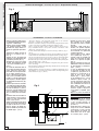
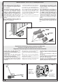
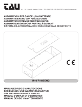
Schema di montaggio -
Assembly description
- Esquema de montaje
Installazione -
Installation
- Instalación
- Verificare l’efficenza delle parti fis-
se e mobili della struttura che dovra’
supportare l’automazione;
- Scegliere, in base al tipo di struttura
e di apertura desiderata, l’esatta
posizione del gruppo motore se-
guendo le applicazioni tipo indica-
te;
- Sistemare una battuta d’arresto in
chiusura e in apertura (fig. 4,
pag. 5)
- Eseguire in base alle misure del
gruppo uno scavo di fondazione nel-
la posizione prescelta (Fig. 3);
- Prevedere uno scarico per I’acqua
che eviti, nella fondazione, ristagni
e successive ossidazioni (Fig. 3 -
part. 1);
- La cassetta di fondazione rende la
posa in opera del gruppo agevole e
veloce. Collocare la stessa all’in-
terno dello scavo con il perno alline-
ato al cardine superiore (Fig. 3 -
part. 2), annegarla nel calcestruzzo
(Fig.3 - part. 3) curandone la messa
in bolla e la corretta posizione del
bordo superiore, che dovra sporgere
di 3 millimetri dal livello terra (Fig.
3 part. 4);
- Prevedere il percorso dei cavi elettri-
ci secondo le disposizioni di coman-
do e sicurezza utilizzando I’apposito
foro sulla cassetta (Fig. 3 - part. 5);
- Ingrassare i perni di rotazione della
cassa di fondazione e della leva
attacco cancello prima del montag-
gio;
- Posizionare l'anta del cancello tra il
cardine superiore e la leva perno; il
cardine e la leva perno dovranno
essere in asse tra loro;
- Saldare accuratamente la leva perno
all'anta del cancello realizzando un
fissaggio a tratti di circa 3 o 4 cm.
lungo la superfice di contatto evi-
tando la saldatura in prossimita' dei
fori filettati (Fig. 3 - part. 6).
- Check the efficency of the fixed and moving parts on the structure
designed to support the automation system;
- Determine, on the basis of the type of structure and opening desired, the exact
position of the motor assembly, following the examples shown;
- Place a closing gate jamb as well as a jamb on aperture (fig. 4, pag. 5);
- Dig a foundation trench in the position selected on the basis of the
dimensions of the unit. (Fig. 3);
- Provide suitable water drainage to avoid rust-causing conditions. (Fig. 3 -
part.1);
- The foundation box simplifies and speeds up the installation of the unit:
install it inside the trench with the stud aligned with the top hinge (Fig. 3 -
part. 2); set it perfectly level in concrete (Fig. 3 - part. 3), ensuring the upper
border is in proper position 3 mm. above ground level. (Fig. 3 - part. 4);
- Determine the layout of the power cables in accordance with operating and
safety standards. (Fig. 3 - part. 5);
- Lubricate rotating pins of the foundation casing and of the gate lock lever
before mounting;
- Place the gate door between the upper hinge and the pin lever; the hinge and
the pin lever must be in axis;
- Carefully weld the lever pin to the gate door, making an intermitent seal of
approximately 3 or 4 cm along the contact surface, avoiding welding near
the threaded holes (fig. 3 - part. 6).
Averiguar la eficacia de las partes
fijas y móviles de la estructura
que tendra que recibir la automa-
tización;
- Seleccionar, según el tipo de es-
tructura y de apertura requerida,
la exacta posición del grupo mo-
tor con relación a las aplicaciones
estándar indicadas.
- Colocar un tope en cierre, tambien
en la apertura (fig. 4, pag. 5);
- Efectuar según las medidas del
grupo una excavación de funda-
mentos en la posición escogida.
(Fig.3);
- Proveer al desagüe para que en el
fundamento no haya sucesivamen-
te estancamientos y oxidaciones.
(Fig.3 - part.1);
- La caja de fundamento hace que
la colocación del grupo sea fácil
y rápida: hay que ponerla en el
interior de la excavación con el
perno en línea con la bisagra
superior (Fig. 3 - part.2), rodear-
la de hormigón (Fig.3 - part.3)
cuidando la puesta a nivel, y la
correcta posición del borde supe-
rior, que tendrá que sobresalir de
unos 3 milímetros del nivel de la
tierra. (Fig.3 - part.4);
- Proveer el recorrido de los cables
eléctricos según las disposicio-
nes de control y seguridad. (Fig.3
- part.5);
- Engrase los pernos de rotación de
la caja de cimentación y de la
palanca de unión a la verja antes
del montaje;
- Coloque la hoja de la cancela
entre el gozne superior y la palan-
ca eje; el gozne superior y la
palanca eje deberán quedar en
eje entre sí;
- Suelde muy bien la palanca eje a
la hoja de la cancela, soldándola
por trechos de 3 o 4 cm a lo largo
de la superficie de contacto, evi-
tando soldar cerca de los aguje-
ros roscados (Fig.3 - part.6).

-5-
ITALIANO • ENGLISH • ESPAÑOL
90° 90°
Fig. 4
DX
SX
Fig. 4-1
A
C
B
Fig. 4-2
C
A
B
SX
DX
110°
110°
140°
140°
A4370
FL180
- Avvitare al braccio motoriduttore la vite
M10 x 100 (A) e il dado M10 (B) come
raffigurato nelle figure 4-1 (installazione
DX) e fig. 4-2 (installazione SX);
- Fissare il motoriduttore alla cassetta di
fondazione tramite i perni filettati e bloc-
candolo con i dadi e le rondelle in dota-
zione;
- Inserire la leva di trasmissione (C) tra il
braccio motore e la leva della cassa ed
elettricamente accostare l’anta alla bat-
tuta d’arresto in chiusura, quindi regola-
re la vite (A) fino ad incontrare la leva di
trasmissione (C).
- Nel collaudo registrare la vite per con-
sentire un’adeguata pressione in battuta
dell’anta in chiusura e permetterne il riag-
gancio nell’operazione di sblocco del
meccanismo.
- A regolazione ultimata bloccare il dado
(B).
- Screw the M10 x 100 boit (A) and the M10
nut (B) on the ratiomotor arm as shown in
figures 4-1 (R installation) and fig. 4-2 (L in-
stallation);
- Fasten the ratiomotor to the foundation cas-
ing with the threaded pins, securing it with
the nuts and washers provided;
- Insert transmission lever (C) between the
motor arm and the casing lever and give the
electric command until the door moves to
the stop ledge during closing, then adjust
screw (A) until meeting transmission lever
(C).
- During inspection, adjust the screw to allow
adequate pressure of the stop ledge when
the door is closed, allowing refastening dur-
ing the mechanism’s release operation.
- When the adjustment is finished, fasten the
nut (B).
- Enrosque en el brazo del motorreductor
el tornillo M10 x 100 (A) y la tuerca M10
(B) como muestran las figuras 4-1 (ins-
talación DCHA) y Fig. 4-2 (instalación IZ-
QDA);
- Sujete el motorreductor a la caja de ci-
mentación mediante los pernos rosca-
dos y bloqueándolo con las tuercas y
arandelas suministradas;
- Introduzca el brazo de transmisión (C)
entre el brazo motor y la palanca de la
caja y accione el mando eléctrico, hasta
acercar la hoja al tope de parada del cie-
rre; entonces regule el tornillo (A) hasta
encontrar el brazo de transmisión (C).
- Durante el ensayo regule el tornillo para
permitir una presión adecuada cuando
la hoja llega al tope de cierre y así permi-
tir el reenganche en la operación de des-
bloqueo del mecanismo.
- Una vez terminada la regulación bloquee
la tuerca (B).
Installazione motoriduttore e regolazione del braccio di trasmissione
Ratiomotor installation and transmission arm adjustment
Instalación del motorreductor y regulación del brazo de transmisión
Battuta d’arresto
Gate jamb
Tope
Battuta d’arresto
Gate jamb
Tope
- Dispositivo per I’apertura dell’anta FINO
A 180°. Questo dispositivo permette an-
che passaggi speciali con aperture a 360°
e multigiro (max. 2 m. ogni anta); per ul-
teriori dettagli vedi relativa documenta-
zione.
- non si può utilizzare con la versione
FROG-A24.
- Device for wing aperture in excess of 180'.
This device can also be used for special pas-
sages with 360° aperture and multiple rota-
tion (max. 2 m. each wing); for further details,
see the relative documentation.
- It cannot be used with the FROG-A24 model.
- Dispositivo para la apertura de la hoja
mas alla de 180°. Este dispositivo con-
siente también unos pasos especiales
con apertura de 360° y multigiro (máx. 2
m. por cada hoja); Para más detalles con-
sulten la documentación dedicada.
- con el modelo FROG-A24 no se puede
utilizarlo.
- Leva di trasmissione per aperture fino a 140° (larghezza max. anta= 2 m).
- Transmission lever for aperture up to 140° (Max. door width= 2 m).
- Palanca de transmision para I’apertura hasta 140° (anchor hoja max. = 2 m).
Accessori -
Accessories
- Accesorios

-6-
ITALIANO • ENGLISH • ESPAÑOL
Fig. 5
3
A4364
A4366
A4365
Fig. 5-B
CAME
Fig. 7
1
0
0
100
Fig. 6
- Nelle situazioni di emergenza (mancan-
za di alimentazione) i meccanismi di
sblocco permettono il riaggancio dell’an-
ta in chiusura.
- E possibile scegliere tra tre diversi mo-
delli di sblocco: modello A4366 fornito
con chiave personalizzata, modello
A4365 con chiave trilobata e modello
A4364 con chiave a leva (Fig. 5-B). E’ con-
sigliabile ingrassare la chiavetta di ag-
gancio dello sblocco (Fig. 5-B - part. 3);
per la procedura di sblocco fare riferi-
mento alla documentazione dei relativi
articoli.
N. B.: le operazioni di sblocco vanno ef-
fettuate nelle manovre di emergenza e ad
impianto non alimentato.
- In emergency situations (power outage) the
release mechanisms allow shutting the door.
- It is possible to select among various re-
lease device models: model A4336 comes
with a custom-made key, model A4365 with
a three-sided key and model A4364 with a
lever key (Fig. 5-B). It is advisable to lubri-
cate the release fastening key (Fig. 5-B part.
3); for the release procedure, refer to docu-
mentation in the related articles.
N. B.: release operations are carried out in
emergency manoeuvres and with the power
off.
- En las situaciones de emergencia (falta
de alimentación) los mecanismos de des-
bloqueo permiten volver a enganchar la
puerta en el cierre.
- Es posible elegir entre los distintos mo-
delos de desbloqueo: modelo A4366 su-
ministrado con llave personalizada, mo-
delo A4365 con llave trilobulada y mode-
lo A43664 con llave de palanca (Fig. 5-
B). Se aconseja engrasar la chaveta de
enganche del desbloqueo (Fig. 5-B det.
3); para el procedimiento de desbloqueo
refiérase a la documentación de cada ar-
tículo.
N. B.: las operaciones de desbloqueo se
realizan en las maniobras de emergencia y
con la instalación desconectada de la ten-
sion.
Sblocco manuale -
Manual release
- Desbloqueo manual
– Portare l’anta a non oltre 100 mm. dalla
battuta d’arresto in apertura (fig. 6);
– Posizionare un microinterruttore sotto il
magnete (fig. 7);
– Portare l’anta a non oltre 100 mm. dalla
battuta d’arresto in chiusura e fissare il
sopracitato microinterruttore;
– Posizionare l’altro microinterruttore sot-
to il magnete, portare l’anta in posizione
di apertura e fissare lo stesso microin-
terruttore.
Regolazione dei microinterruttori di rallentamento FROG-A24
Regulation of FROG-A24 deceleration microswifches
Regulacion microinterruptors de reduccion de la marcha FROG-A24
- Move the door to not more than 100 mm.
beyoind the fully-open position (fig. 6);
- Position a microswitch under the magnet (fig.
7);
- Move the door to not more than 100 mmbe-
yoind the fully closed position and fasten the
microswitch in position;
- Position the second microswitch under the
magnet, move the door to the open position
and fasten the microswitch in position.
- Colocar la hoja a no más de 100 mm. del
punto de contacto en la fase de apertura
(fig. 6);
- Colocar un microinterruptor debajo del
imán (fig. 7);
- Colocar la hoja a no mas de 100 mm. del
punto de contacto en la fase de cierre y
fijar dicho microinterruptor;
- Colocar el otro microinterruptor debajo
del imán, disponer la hoja en posición de
apertura y fijar dicho microinterruptor.
Lamiera porta
finecorsa
Limit switch
support
Chapa porta-
final de carrera
Magnete
Magnet
Imán
Microinterruttori
Microswitches
Microinterruptors

-7-
ITALIANO • ENGLISH • ESPAÑOL
Manutenzioni periodiche -
PERIODIC MAINTENANCE -
Mantenimiento periódico
- Ingrassare periodicamente il perno di
rotazione togliendo la vite (pag. 3, fig. 1-
1); pulire e ingrassare la chiavetta dello
sblocco (pag. 6, fig.5-B, part. 3).
- The release unit and the transmission lever
should be grease lubricated from time to time
(p. 3, fig. 1- 1); clean and lubricate the release
key(pg. 6, fig.5-B, part. 3).
- Lubricar periódicamente con grasa el
grupo de desbloqueo y la palanca de
transmisión (pág. 3, fig. 1-1); limpie y
engrase la chaveta del desbloqueo (päg.
6, fig.5-B, part. 3).
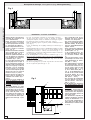
COLLEGAMENTI ELETTRICI -
ELECTRICAL CONNECTIONS -
CONEXIONES ELÉCTRICAS
FROG A - FROG AV
- E’ consigliabile fare le connessioni del
cavo motoriduttore in scatole di deriva-
zione;
- Per i collegamenti elettrici e ulteriori indi-
cazioni riguardanti le funzioni, fare riferi-
mento alla documentazione delle relative
schede elettroniche di comando (ZA3,
ZA4, ZA5 o ZM2).
- It is advisable to make gearmotor cable con-
nections within connector blocks.
- For the electrical connections and further
instructions regarding the functions, refer to
the documentation for the appropriate elec-
tronic control boards (ZA3, ZA4, ZA5 or
ZM2).
- Se aconseja hacer las conexiones del
cable del motorreductor en cajas de
paso.
- Para las conexiones eléctricas y otras
indicaciones acerca de las funciones, re-
férase a la documentación de las respec-
tivas tarjeta electrónicas de mando (ZA3,
ZA4, ZA5 o ZM2).
R1-Ra1
Microinterruttore di rallentamento motore 1 in
apertura.
Microswitch-deceleration of motor 1 on aperture.
Microinterruptor deceleración motor 1 en la fase
de apertura
R1-Rc1
Microinterruttore di rallentamento motore 1 in
chiusura.
Microswitch-deceleration of motor 1 on closure.
Microinterruptor deceleración motor 1 en la fase
de cierre
R2-Ra2
Microinterruttore di rallentamento motore 2 in
apertura.
Microswitch-doceleration of motor 2 on aperture.
Microinterruptor deceleración motor 2 en la fase
de apertura
R2-Rc2
Microinterruttore di rallentamento motore 2 in
chiusura.
Microswitch-doceleration of motor 2 on closure.
Microinterruptor deceleración motor 2 en la fase
de cierre
Per ulteriori indicazioni riguardanti le fun-
zioni, fare riferimento alla documentazio-
ne tecnica dei quadri elettrici ZL14 - ZL19;
For further information regarding the functions,
refer to the technical documentation of the
ZL14 – ZL 19 electrical panels;
Para más información sobre las funciones
consulten la documentación técnica de los
cuadros eléctricos ZL14 - ZL19.
C
OLLEGAMENTI ELETTRICI -
ELECTRICAL CONNECTIONS -
CONEXIONES ELÉCTRICAS
FROG A24
Fig. 7
Motore 2
Motor 2
Motor 2
Morsettiera quadro comando
Control panel terminal block
Caja de bornes cuadro de mando
marrone-
brown
-marrón
marrone-
brown
-
marrón
blu-
blue
-azul
Fig. 6
Morsettiera quadro comando
Control panel terminal block
Caja de bornes cuadro de mando
Motore 1
Motor 1
Motor 1
marrone-
brown
-marrón
marrone-
brown
-
marrón
blu-
blue
-azul

CANCELLI AUTOMATICI
CAME LOMBARDIA S.R.L.______COLOGNO M. (MI) (+39)
02 26708293
(+39) 02 25490288
CAME SUD S.R.L. ___________________NAPOLI
(+39) 081 7524455 (+39) 081 7529109
CAME (AMERICA) L.L.C.____________MIAMI (FL)
(+1) 305 5930227 (+1) 305 5939823
CAME AUTOMATISMOS S.A__________MADRID (+34)
091 5285009
(+34) 091 4685442
CAME BELGIUM NU- SA______________LESSINES
(+32) 068 333014 (+32) 068 338019
CAME FRANCE S.A.____NANTERRE CEDEX (PARIS) (+33)
01 46130505
(+33) 01 46130500
CAME GMBH________KORNTAL BEI (STUTTGART) (+49)
07 11839590
(+49) 07 118395925
CAME GMBH____________SEEFELD BEI (BERLIN) (+49)
03 33988390
(+49) 03 339885508
CAME PL SP.ZO.O______________WARSZAWA (+48)
022 8365076
(+48) 022 8369920
CAME UNITED KINGDOM LTD___NOTTINGHAM (+44)
01159 210430
(+44) 01159 210431
CAME CANCELLI AUTOMATICI S.P.A.
DOSSON DI CASIER (TREVISO)
(+39) 0422 4940 (+39) 0422 4941
SISTEMA QUALITÀ
CERTIFICATO
ASSISTENZA TECNICA
NUMERO VERDE
800 295830
W
EB
www.came.it
E-MAIL
Tutti i dati sono stati controllati con la massima cura. Non ci assumiamo
comunque alcuna responsabilità per eventuali errori od omissioni.
All data checked with the maximum care. However, no liability is accepted
for any error or omission.
Todos los datos se han controlado con la máxima atención. No obstante
no nos responsabilizamos de los posibles errores u omisiones.
DICHIARAZIONE DEL FABBRICANTE
Ai sensi dell’Allegato II B della Direttiva Macchine 98/37/CE
I Rappresentanti della
CAME Cancelli Automatici S.p.A.
via Martiri della Libertà, 15
31030Dosson di Casier - Treviso - ITALYtel
(+39) 0422 4940 - fax (+39) 0422 4941
internet: www.came.it - e-mail: [email protected]
Dichiarano sotto la propria responsabilità che i/il prodotto/i denominato/i ...
… sono conformi alle disposizioni legislative Nazionali che traspongono le seguenti Direttive
Comunitarie (dove specificatamente applicabili):
DIRETTIVA MACCHINE 98/37/CE
DIRETTIVA BASSA TENSIONE 73/23/CEE - 93/68/CEE
DIRETTIVA COMPATIBILITÀ ELETTROMAGNETICA 89/336/CEE - 92/31/CEE
DIRETTIVA R&TTE 1999/5/CE
Inoltre, dichiara che il/i prodotto/i, oggetto della presente dichiarazione, sono costruiti nel rispetto
delle seguenti principali norme armonizzate:
EN 292 PARTE 1ª E 2ª SICUREZZA DEL MACCHINARIO.
EN 12453 CHIUSURE INDUSTRIALI, COMMERCIALI …
EN 12445 CHIUSURE INDUSTRIALI, COMMERCIALI …
EN 60335 - 1 SICUREZZA NEGLI APPARECCHI AD USO DOMESTICO ...
EN 60204 - 1 SICUREZZA DEL MACCHINARIO.
EN 50081 - 1 E 2COMPATIBILITÀ ELETTROMAGNETICA.
EN 50082 - 1 E 2COMPATIBILITÀ ELETTROMAGNETICA.
AVVERTENZA IMPORTANTE!
È vietato mettere in servizio il/i prodotto/i, oggetto della presente dichiarazione, prima del
completamento e/o incorporamento, in totale conformità alle disposizioni della Direttiva Macchine
98/37/CE
Firma dei Rappresentanti
Documentazioni tecniche specifiche dei prodotti sono disponibili a richiesta!
Data della presente dichiarazione 07/12/2001
Also, they furthermore represent and warrant that the product/s that are the subject of the present
Declaration are manufactured in the respect of the following main harmonized provisions:
EN 292 PART 1 AND 2MACHINERY SAFETY.
EN 12453 INDUSTRIAL, COMMERCIAL AND OTHER CLOSING MECHANISMS.
EN 12445 INDUSTRIAL, COMMERCIAL AND OTHER CLOSING MECHANISMS.
EN 60335 - 1 SAFETY IN APPARATUSES FOR HOME USE.
EN 60204 - 1 MACHINERY SAFETY.
EN 50081 - 1 AND 2ELECTROMAGNETIC COMPATIBILITY.
EN 50082 - 1 AND 2ELECTROMAGNETIC COMPATIBILITY.
IMPORTANT CAUTION!
It is forbidden to market/use product/s that are the subject of this declaration before completing and/
or incorporating them in total compliance with the provisions of Machinery Directive 98/37/CE
Signatures of the Representatives
Specific technical documentation on the products is available on request!
Date of the present declaration 07/12/2001
MANUFACTURER’S DECLARATION
As per Enclosure II B of Machinery Directive 98/37/CE
The representatives of
CAME Cancelli Automatici S.p.A.
via Martiri della Libertà, 15
31030 Dosson di Casier - Treviso - ITALY
tel (+39) 0422 4940 - fax (+39) 0422 4941
internet: www.came.it - e-mail: [email protected]
Hereby declare, under their own respons ibility, that the product/s called ...
… comply with the Italian National Legal Provisions that transpose the
following Community Directives (where specifically applicable):
MACHINERY DIRECTIVE 98/37/CE
LOW VOLTAGE DIRECTIVE 73/23/EEC - 93/68/EEC
LECTROMAGNETIC COMPATIBILITY DIRECTIVE 89/336/EEC - 92/31/EEC
R&TTE DIRECTIVE 1999/5/CE
DECLARACION DEL FABRICANTE
De conformidad con el Anexo II B de la Directiva de Máquinas 98/37/CE
Fecha de la presente declaración 07/12/2001Adjunta a la documentación técnica (el original de la Declaración está disponible previa petición)
Los Representantes de la compañía
CAME Cancelli Automatici S.p.A.
via Martiri della Libertà, 15
31030 Dosson di Casier - Treviso - ITALY
tel (+39) 0422 4940 - fax (+39) 0422 4941
internet: www.came.it - e-mail: [email protected]
Declaran bajo su responsabilidad que el/los producto/s denominado/s ...
… cumplen con las disposiciones legislativas nacionales que trasponen las siguientes
Directivas Comunitarias (donde específicamente aplicables):
DIRECTIVA DE MÁQUINAS 98/37/CE
DIRECTIVA DE BAJA TENSIÓN 73/23/CEE - 93/68/CEE
DIRECTIVA DE COMPATIBILIDAD ELECTROMAGNÉTICA 89/336/CEE - 92/31/CEE
DIRECTIVA R&TTE 1999/5/CE
Los productos objeto de esta declaración están fabricados respetando las siguientes normas
armonizadas:
EN 292 PARTE 1ª Y 2ª SEGURIDAD DE LAS MÁQUINAS.
EN 12453 CIERRES INDUSTRIALES, COMERCIALES …
EN 12445 CIERRES INDUSTRIALES, COMERCIALES …
EN 60335 - 1 SEGURIDAD DE LOS APARATOS PARA USO DOMÉSTICO...
EN 60204 - 1 SEGURIDAD DE LAS MÁQUINAS.
EN 50081 - 1 E 2COMPATIBILIDAD ELECTROMAGNÉTICA.
EN 50082 - 1 E 2COMPATIBILIDAD ELECTROMAGNÉTICA.
AVVERTENZA IMPORTANTE!
Está prohibido hacer uso de el/los producto/s, objeto de la presente declaración antes de completarlo/
s y/o incorporarlo/s en total conformidad a las disposiciones de la Directiva de Máquinas 98/37/CE.
Firma de los Representantes
Documentación técnica específica de los productos está disponible previa petición
Enclosed with the technical documentation (the original copy of the Declaration is available on request)
Allegata alla documentazione tecnica (l’originale della Dichiarazione è disponibile a richiesta)
RESPONSABILE TECNICO
Sig. Gianni Michielan
PRESIDENTE
Sig. Paolo Menuzzo
TECHNICAL MANAGER
Mr. Gianni Michielan
MANAGING DIRECTOR
Mr. Paolo Menuzzo
RESPONSABLE TÉCNICO
Sr. Gianni Michielan
PRESIDENTE
Sr. Paolo Menuzzo
FROG-A • FROG-AV • FROG-A24
FROG-B • FROG-BI • A4364 • A4365 • A4366 • A4472 • A4370
FL-180 • LOCK 81 • LOCK 82 • LOCK 2
FROG-A • FROG-AV • FROG-A24
FROG-B • FROG-BI • A4364 • A4365 • A4366 • A4472 • A4370
FL-180 • LOCK 81 • LOCK 82 • LOCK 2
FROG-A • FROG-AV • FROG-A24
FROG-B • FROG-BI • A4364 • A4365 • A4366 • A4472 • A4370
FL-180 • LOCK 81 • LOCK 82 • LOCK 2

Documentazione
Tecnica
S45
rev. 2.2
07/2002
©
CAME
CANCELLI
AUTOMATICI
FROG A
CANCELLI AUTOMATICI
SCHEDA COMANDO
CONTROL BOARD
CARTE DE COMMANDE
STEUERPLATINE
TARJETA DE MANDO
119AS45-2
FRANÇAIS/NEDERLANDS/DEUTSCH
SÉRIE FROG |
SERIE FROG
|
BAUREIHE
FROG
8
6
5
2
4
7
10
9
3
1
9
1
10
3
4x1,5
3x1,5
230V
4x1
2x1,5
RG58
3x1
5x1
2x1
4x1
RX
TX
RX
TX
4x1,5
2x1
11
10
1 - FROG Antriebsmotor
2 - Schalttafel im Antrieb
3 - IR Lichtschranke
4 - Funkempfänger
5 - Schlsselschalter
6 - Außenantenne
7 - Interne Schalter
8 - Blinkleuchte “Tor in Bewegung”
9 - Lichtschrankeensäule
10 - Abeitungsdose für das Kabel vom
Getriebemotor (Es wird empfohlen, die
Anschlsse vom Kabel des Getriebe-
motors in der Ableitungsdose
durchzuführen)
11 - Handsender
Installation type Standard montage
1 - Groupe FROG
2 - Armoire de commande incorporée
3 - Photocellules de sécurité
4 - Récepteur radio
5 - Sélecteur a clé
6 - Antenne de reception
7 - Poussoir interne
8 - Clignotant de mouvement
9 - Colonne pour photocellule
10 - Boîte de derivation pour câble du
motoréducteur (il est conseillé
d’effectuer les connexions du câble du
motoréducteur dans les boîtes de
dérivation)
11 - Emetteur
Câbles d'alimentation moteur:
2 x 1.5 mm
2
jusqu'à 20 m
2 x 2.5 mm
2
jusqu'à 30 m
Câbles de branchement microinterrupteurs:
3 x 1 mm
2
Antriebsmotor-Verbindungskabel:
2 x 1.5 mm
2
bis 20 m
2 x 2.5 mm
2
bis 30 m
Microschalter-Verbindungskabel:
3 x 1mm
2
FROG A24
Automatisme pour portails à battant (montage enterré)
Automatisatie voor draaihekken (ondergrondse installatie)
Automatisierung für Flügeltore (Unterflurmontage)
Standaardinstallatie
1 - Motor FROG
2 - Stuurkast
3 - Veiligheidsfotocellen
4 - Ontvanger
5 - Sleutelschakelaar
6 - Antenne
7 - Drukknop
8 - Flitslamp
9 - Paaltje voor fotocel
10 - Verdeeldoosje voor motor (het is aan te
raden om de aansluitingen in de
verdeeldoos te maken)
11 - Zender
Bekabeling voor motor:
2 x 1.5 mm
2
tot 20 m
2 x 2.5 mm
2
tot 30 m
Bekabeling voor microswitches:
3 x 1 mm
2

-2-
FRANÇAIS • NEDERLANDS • DEUTSCH
Toebehoren:
A4370 Overbrengingsarm voor opening tot max. 140° (max. 2
m. per vleugel);
FL180 Snufje voor de opening van de deur tot op 180°; met de
FL180 kunnen zelfs hoeken tot 360° bereikt worden (max. 2 m per
vleugel); Kan niet gebruikt worden bij de FROG A24;
LOCK81 Electrisch slot met enkele cilinder;
LOCK82 Electrisch slot met dubbele cilinder.
Description:
- Automation pour portails à battant pour montage enterré dans une
caisse de fondations (FROG-B / FROG BI);
- Conçu et construit entièrement par CAME Cancelli Automatici S.p.A.
- Degré de protection IP 67;
- Il est garanti 24 mois sauf en cas d’altérations.
Versions:
Moteur monophasé 230V a.c. / 200 W, avec protecteur
thermique incorporé;
Moteur monophasé 230V a.c. / 200 W, avec protecteur
thermique incorporé;
Moteur monophasé 24V d.c. / 180 W, à aimants perma-
nents.
Mécanismes de déblocage:
Déblocage mécanique avec clé à levier;
Déblocage mécanique avec clé à trois lobes;
Déblocage mécanique avec cylindre EURO DIN.
Accessoires:
Lévier de transmission pour ouverture jusq’a’ 140° (max.
2 m. pour chaque vantail);
Dispositif pour ouvrir la porte jusqu’à 180°; Ce dispositif
permet également des passages spéciaux avec des ouvertures à
360° (max. 2 m. pour chaque vantail); Il ne peut pas être utilisé avec la
version FROG A24;
Electro-serrure de blocage à cylindre unique;
Electro-serrure de blocage à double cylindre.
Limites d'emploi:
- Dimensions des portes jusq’a’ 3,5 mètres;
- L’ouverture standard maximum de la porte est de 110°;
Attention ! Vérifiez que l’appareillage de commande, de sécurité et les
accessoires sont des produits originaux CAME afin de garantir l’instal-
lation et d’en faciliter le montage et l’entretien.
FRANÇAIS
Caractéristiques généralés
FROG A24
FROG AV
FROG A
A4364
A4365
A4366
A4370
FL180
LOCK 81
LOCK 82
Gebruikslimieten:
- Max. lengte per vleugel: 3,5 m;
- Maximum standaard opening: 110°;
Technische kenmerken
Aandacht ! Om te voldoen aan de geldende veiligheidsnormen is het
aangeraden om originele CAME-veiligheidstoebehoren te gebruiken.
NEDERL
Beschrijving:
- Ondergrondse automatisatie voor draaihekken te plaatsen in inbouw-
behuizing (FROG-B / FROG BI);
- Ontworpen en geproduceerd door CAME Cancelli Automatici S.p.A.
- Waterdichtheidsgraad IP 67;
- 24 maanden garantie behalve bij verkeerde montage of foutief gebruik.
Versies:
FROG A Monofasige motor met ingebouwde thermische
230V AC - 200 W;
FROG AV Monofasige motor met ingebouwde thermische veiligheid
230V AC - 300 W;
FROG A24 Motor met permanente magneten
24V DC - 180 W.
Ontgrendelingssystemen
A4364 Mechanische deblokkering met hendel;
A4365 Mechanische deblokkering met drielobbige sleutel;
A4366 · Mechanische deblokkering met cilinder EURO DIN.
- Les valeurs indiquées sont valables pour un service à usage rési-
dentielle; pour un service particuliérement intensif, il convient de ré-
duire ces valeurs de 10 a 20%.
* Il est conseillé de prévoir une serrure électrique si le vantail dépasse
2,5 m
- De opgegeven waarden zijn voor particulier gebruik. in geval van intensief
gebruik moeten deze waarden met 10 à 20% verminderd worden
Largeur du vantail
m.
Poids du vantail
Kg.
2.00 800
2.50 600
*
3.50
400
Torbreite
m.
Gewicht
K
g
.
2.00 800
2.50 600
*
3.50
400

-3-
FRANÇAIS • NEDERLANDS • DEUTSCH
Fig. 1
Fig. 1-1
405 330
160
60
Einsatzbereich:
- Torflügeldimensionen bis 3.5 Meter;
- Maximale Standard Toröffnung: 110°;
Achtung! Wir empfehlen original CAME-Schalt- und -Sicherheitsvorrich-
tungen mit entsprechendem Zubehör zu montieren, um die einwandfreie
Montage und die problemlose Wartung der Anlage zu gewährleisten.
Allgemeine merkmale
Baschreibung:
- Antrieb für Flügeltore zur Montage in im Boden versenkten Funda-
mentkasten (FROG-B / FROG-BI);
- Vollkommen von der CAME Cancelli Automatici S.p.A.
- Schutzklasse IP 67;
- Garantie: 24 Monate, vorbehaltlich unsachgemäßer Handhabung
und Montage.
Ausführungen:
Motor Einphasig 230V Wechselstrom / 200 W, mit inte-
griertem Thermoschutzschalter;
Motor Einphasig 230V Wechselstrom / 300 W, mit inte-
griertem Thermoschutzschalter;
Motor Einphasig 24V Gleichstrom / 180 W, mit Dauerma-
gneten ausgerüstet.
Entriegelungsmechanismen:
Mechanische Freigabe mit Hebelschlüssel;
Mechanische Freigabe mit Dreipaßschlüssel;
Mechanische Freigabe mit EURO DIN-Zylinder.
Zubehör:
Hebelarm für 140° öffnungwinkel (max 2 m. breite Torflü-
gel);
Vorrichtung zum Öffnen des Türflügels bis auf 180°. Die-
se Vorrichtung erlaubt aucht Sonderausführungen mit um 360° öffnen-
dem Tor (max. 2 m. breite Törflugel). Bei der Ausführung FROG A24
Kann FL 180 nicht montiert werden;
Elektrische Schließanlage mit Einzelzylinder;
Elektrische Schließanlage mit Doppelzylinder.
FROG A24
FROG AV
FROG A
A4364
A4365
A4366
A4370
FL180
LOCK 81
LOCK 82
* Réglable au moyen des armoires de commande CAME ** Utilisation intensive;
* Regelbaar d.m.v. Came-stuurkast ** intensief gebruik
* Ûber CAME-Sreuergeräte regelbar ** Starkbetrieb;
FROG-B / FROG-BI
Mesures d'encombrement -
Afmetingen
- Außenabmessungen
Caractéristiques technique -
Technische kenmerken
- Technische Daten
DEUTSCH
- die angegebenen Werte gelten für den Einsatz in Wohnanlagen; bei be-
sonders starkem Finsatz sind diese Werte un 10% bis 20% zu reduzie-
ren.
* Falls die Tür 2,5 m uberschreiter, ist es ratsam ein elektrisches Schloß
anzubringen
Torbreite
m.
Torgewicht
Kg.
2.00 800
2.50 600
*
3.50
400
MOTO-
RÉDUCTEUR
POIDS ALIMENTATION ABSORPTION PUISSANCE
INTERMITTENCE
DE TRAVAIL
COUPLE
MAX
RAPPORT DE
REDUCTION
TEMPS
COURSE
CONDEN-
SATEUR
MOTOR GEWICHT VOEDING VERBRUIK VERMOGEN
ARBEIDS-
TUSSENTIJD
KOPPEL REDUCTIE LOOPTIJD
CONDEN-
SATOR
GETRIEBE-
MOTOR
GEWICHT
STROMVER-
SORGUNG
STROM-
AUFNAHME
LEISTUNG
EINSCHALT-
DAUER
MAX DREH-
MOMENT
UNTER-
SETZUNGS-
VERHÄLTNIS
LAUFZEIT
KONDEN-
SATOR
FROG A 11 Kg 230V a.c. 1,9 A 200 W 30 %
* 320 Nm
1/1152
18 s 16 µF
FROG A24 11,5 Kg 24V d.c. 15 A max 180 W ** 16÷45 s -
FROG AV 11 Kg 230V a.c 2,5 A 300 W 30 %
* 240 Nm
9 s 20 µF

-4-
FRANÇAIS • NEDERLANDS • DEUTSCH
67
67
160
100 60
3
Fig. 2
Fig.3
67
2
5
7
1
6
4
3
3
- Vérifier l’efficience des parties fixes
et mobiles de la structure où l’on
place l’automatisation;
- Choisir, selon le type de structure et
l’ouverture désirée, la position
exacte du groupe moteur en suivant
les applications type indiquees;
- Placer un dispositif d’arrêt à la fer-
meture et même à l’ouverture
(fig. 4, pag. 5);
- Effectuer une tranchée de fondation
dans la position choisie, selon les
dimensions du groupe. (Fig. 3);
- Prévoir un système d’évacuation de
l’eau qui empêche les stagnations
et les oxydations successives dans
la fondation. (Fig. 3 - part.1);
- Le caisson delain fondation rend la
pose du groupe facile et rapide. le
placer à l’intérieur de la tranchée en
alignant le pivot au gond supérieur
(Fig. 3 part. 2 page 4), le couvrir de
béton (Fig. 3 - part. 3), en veillant à
la mise à niveau et à la position
correcte du bord supérieur qui doit
dépasser de 3 mm., par rapport au
niveau du sol. (Fig. 3 - part. 4);
- Prévoir le parcours des câbles élec-
triques selon les dispositions de
commande et de sécurité. (Fig. 3 -
part. 5);
- Graisser les axes de rotation de la
caisse de fondations et du levier
d’accouplement du portail avant le
montage;
- Positionner le vantail du portail en-
tre le gond supérieur et le levier
pivot; le gond et le levier pivot de-
vront être dans l’axe l’un de l’autre;
- Souder soigneusement le levier pi-
vot au vantail du portail à l’aide
d’une fixation à traits d’environ 3 ou
4 cm le long de la superficie de
contact en évitant de souder à proxi-
mité des trous filetés (Fig. 3 -part.
6).
- Die feststehenden und die be-
weglicken Teile der zu automati-
sierenden Tore überprüfen;
- Die genaue Position der Motor-
Gruppe, je nach Struktur und ge-
wünschter Öffnung, der Beschrei-
bung der StandardAnwendungen
folgend, wählen;
- Einen mechanischen Endanschlag
in Öffnungs und Schließstellung
vorsehen (Abb. 4, S. 5);
- In der gewahlten Position, ent-
sprechend den Maßen der Grup-
pe, eine Grube ausheben. (Abb.
3);
- Für guten Wasserabflu8 sorgen,
um Stauungen und daraus erfol-
gende Oxydierungen zu vermei-
den (Abb. 3 - Teil.1);
- Der Fundamentkasten vereinfacht
die Fundamentierung; den Kas-
ten in die Grube stellen, den Zap-
fen auf gleicher Linie mit den
oberen Türangel (Abb. 3 - Teil.
2), ihn in Beton hüllen (Abb. 3-
Teil. 3), auf die Nivellierung ach-
ten und auf die genaue Position
des oberen Randes, der 3 mm.
oberhalb des Erdniveaus sein
mu8. (Abb. 3 - Teil. 4);
- Die Verlegung der Elektrokabel
nach den Betriebs und Sicher-
heitsvorschriften vorbereiten.
(Abb. 3 - Teil. 5);
-Vor der Montage die Angelzapfen
vom Fundamentkasten und vom
Anschlußhebel des Tors ab-
schmieren;
- Den Torflügel zwischen dem obe-
ren Angelzapfen und dem Bolzen-
hebel plazieren. Der Angelzapfen
und der Bolzenhebel müssen auf
einer Linie liegen;
- Den Bolzenhebel sorgfältig am
Torflügel anschweißen und dabei
entlang der Kontaktfläche ca. 3
bis 4 cm große Schweißnähte an-
legen. Nicht in der Nähe der Ge-
windebohrungen schweißen (Abb.
3, teil 6)!
Description de montage -
Montagebeschrijving
- Montageanordung
Installation -
Installatie
- Installation
- De vaste en beweegbare onderdelen op hun werking controleren;
- De juiste positie van de motor, volgens de structuur en gewenste
openingshoek bepalen, hierbij de standaard voorzieningen volgend;
- Een aanslag bij openen en sluiten voorzien (Fig. 4, blz. 5);
- Graaf een fundering volgens de gekozen positie en afmetingen van de
groep (Fig 3);
- Voorzie een afwatering om vroegtijdige oxidering te voorkomen (Fig. 3
- deel 1);
- De inbouwbehuizing laat een snelle en gemakkelijke installatie toe. Plaats
de behuizing in de gleuf en zorg voor een goede uitlijning met het
draaipunt van het hek (Fig. 3 - 2 blz. 4), stort nu het beton (Fig. 3 - 3),
en bepaal nu de correcte positie zodanig dat de bovenzijde 3 mm boven
het grondoppervlak komt (Fig. 3 - 4);
Leg de aansluitingskabels voor de motoren en toebehoren. (Fig. 3 - 5);
- Alvorens de motor te plaatsen, smeert u de assen van inbouwbehuizing
en overbrengingsarm.
- Plaats nu het hek op de bevestigingsarm. Zorg ervoor dat beide
draaipunten overeenstemmen;
- Las het hek zorgvuldig vast op de arm. Zorg wel dat u niet in de buurt
van de voorgeboorde gaten last (Fig. 3 - 6).

-5-
FRANÇAIS • NEDERLANDS • DEUTSCH
90° 90°
Fig. 4
DX
SX
Fig. 4-1
A
C
B
Fig. 4-2
C
A
B
SX
DX
110°
110°
140°
140°
A4370
FL180
- Visser la vis M10 x 100 (A) et l’écrou M10
(B) au bras du motoréducteur comme
indiqué sur les figures 4-1 (installation
DROITE) et 4-2 (installation GAUCHE);
- Fixer le motoréducteur à la caisse de fon-
dations à l’aide des goujons filetés en le
bloquant avec les écrous et les rondelles
fournis de série;
- Placer le levier de transmission (C) entre
le bras moteur et le levier de la caisse et
donner une commande électrique pour
rapprocher le vantail de la butée d’arrêt
en fermeture. Régler ensuite la vis (A)
jusqu’à rencontrer le levier de transmis-
sion (C).
- Durant la phase d’essai, régler la vis pour
permettre une pression appropriée en
butée du vantail en fermeture et de le rac-
crocher pendant l’opération de débloca-
ge du mécanisme.
- Bloquer l’écrou (B) quand le réglage est
terminé.
- Die Schraube M10 x 100 (A) und die Mut-
ter M10 (B) so Arm vom Getriebemotor
anshweißen, wie auf Abb. 4-1 (Installati-
on rechts) und Abb. 4-2 (Installation links)
zu sehen ist;
- Den Getriebemotor mit den Gewindestif-
ten am Fundamentkasten befestigen und
mit den beiliegenden Unterlegscheiben
und Muttern blockieren;
- Den Antriebsarm (C) zwischen den Mo-
torarm und den Hebel vom Fundament-
kasten einsetzen und den Torflügel durch
Einschalten vom Elektromotor bis zum
Endanschlag schließen. Dann die
Schraube (A) regulieren, bis sie am An-
triebsarm (C) anschlägt.
- Bei der Abnahmeprüfung die Schraube
so einstellen, daß beim Anschlag vom
Torflügel beim Schließen ein angemes-
sener Druck ausgeübt wird und das er-
neute Einrasten bei Entriegelung mög-
lich ist.
- Nach erfolgter Einstellung die Mutter (B)
anziehen.
Installation du motoreducteur et reglage du bras de transmission
Installatie van de motor en regeling van de overbrengingsarm
Installation vom getriebemotor und einstellung vom antriebsarm
Draai de schroef M10 x 100 (A) en de moer
M10 (B) in de arm van de motor zoals afge-
beeld op fig. 4-1 (rechtse installatie) en fig. 4-2
(linkse installatie);
- Bevestig de motor in de inbouwbehuizing met
de voorziene moeren en rondellen;
- Plaats de overbrengingsarm (C) tussen de
arm van de motor en de arm van de behui-
zing. Geef een puls om de eindeloop bij slui-
ten te regelen. Regel daarna schroef (A) zo-
dat die tegen de overbrengingsarm komt (C)
- Zorg ervoor dat de druk op de aanslag bij
sluiten niet te hoog is zodat de vleugel zon-
der veel problemen te ontgrendelen is..
- Na deze regeling draait u schroef (B) vast.
Arrête
Grondaanslag
Toranschlag
Arrête
Grondaanslag
Toranschlag
- Dispositif pour une ouverture du vantail
supérieure a 180°. Ce dispositif permet
également des passages spéciaux avec
des ouvertures à 360° et multitour (max.
2 m. pour chaque vantail); pour d’ulté-
rieur détails, voir la documentation cor-
rispondante.
- iI ne peut pas etre utilisé avec la version
FROG-A24.
-Vorrichtung zur Erhöhung des Toröff-
nungswinkels uber 180°. Diese Vorrich-
tung erlaubt aucht Sonderausführungen
mit um 360° öffnendem Tor und Multiro-
tation (max. 2 m. breite Törflugel); Weite-
re Informationen und Details befinden
sich in der zugehörigen Dokumentation.
- Bei der Ausfuhrung FROG-A24 Kann FL
18O nicht montiert uvorden.
Accessoires -
Toebehoren
- Zubehör
- Lévier de transmission pour ouverture jusqu’a 140° (Largeur max. de la porte = 2m).
- Overbrengingsarm voor openingshoek tot 140° (Max. lengte per vleugel = 2m)
- Hebelarm fur 140° Grad öffnungwinkel (Max. breite des Torflügels = 2 m). .
- Toebehoren voor een openingshoek van
meer dan 140°. Met de FL180 kunnen zelfs
openingshoeken tot 360° bereikt worden. Een
andere mogelijkheid is “multi-tour”, meerde-
re omwentelingen. De maximale breedte is
2m per vleugel. Meer info vindt u in de bijge-
voegde technische documentatie.
- Kan niet gebruikt worden met de FROG-A24.

-6-
FRANÇAIS • NEDERLANDS • DEUTSCH
Fig. 5
3
A4364
A4366
A4365
Fig. 5-B
CAME
Fig. 7
1
0
0
100
Fig. 6
- En cas d’urgence (coupure de courant),
les mécanismes de déblocage permettent
de raccrocher la porte durant la phase de
fermeture.
- Possibilité de choisir entre trois modèles
de déblocage différents: modèle A4336
fourni avec une clé personalisée, modèle
A4365 avec clé à levier (Fig. 5-B). Il est
conseillé de graisser la clé pour accro-
cher le dispositif de déblocage (Fig. 5-B
part. 3); se référer à la documentation des
différentes articles pour la procédure de
déblocage.
N. B.: les opérations de déblocage doivent
être effectuées durant les manoeuvres de
d’urgence et quand l’installation n’est pas
alimentée.
Déblocage manuel -
Manuele ontgrendeling
- Manuelle Entriegelung
- Positionner le vantail de façon à ce qu’il se
trouve, par rapport à la position “entière-
ment ouverte”, à une distance non supérieu-
re à 100 mm. (fig. 6);
- Positionner un microinterrupteur sous
l’aimant (fig. 7);
- Positionner le vantail de façon à ce qu’il se
trouve, par rapport à la position “entière-
ment fermé”, à une distance non supérieure
à 100 mm. et fixer le micro interrupteur cides-
sus mentionné;
- Positionner l’autre microinterrupteur sous
l’aimant, puls amener le vantail dans la posi-
tion d’ouverture et fixer le microinterrupteur.
- Torflügel bis höchstens 100 mm. vom
Anschlag “Öffnen” bringen (Abb. 6);
- Einen Mikroskalter unter den Magnet pla-
zieren (Abb. 7);
- Torflügel bis höchstens 100 mm. vom
Anschlag “Schließen” bringen und den
Mikroschalter befestigen;
- Den zweiten Mikroschalter unter den
Magnet plazieren, Tor in Öffnungsste-
lung bringen und den Microschalter be-
festigen.
- Eindeloop “openen” plaatsen (Fig. 6);
- Plaats de microschakelaar onder de magneet
(Fig. 7);
- De vleugel op ongeveer 100mm van de
eindeloop “sluiten” plaatsen en de micro-
schakelaar instellen.;
- De tweede microschakelaar onder de mag-
neet plaatsen, poort openen en microswitch
vastmaken.
Réglage des microinferrupteurs de ralentissement FROG-A24
Instelling microschakelaars vertraging FROG-A24
Einstellung der Mikroschalter Vorrichtung FROG-A24
Support fin de
course
Bevestigings plaat
eindelopen
Endanschlag-
blech
Aiman
Magneet
Magnet
Microinterrupteurs
Microschakelaar
Mikroschalter
· In noodsituaties (ontbreken van stroom) zor-
gen de deblokkeringsmechanismen voor de
correcte sluiting van de deur.
- Dit systeem is in drie versies verkrijgbaar
(fig. 5-B) : A4366, met een gepersonaliseer-
de DIN-sleutel, A4365 met driehoekssleutel
en A4364 met hendel. Wij raden aan om slot
en sleutel regelmatig te smeren. Wij verwij-
zen naar de specifieke documentatie voor
de werkwijze bij ontgrendeling.
NB: Het ontgrendelen van het hek dient enkel
in geval van nood te gebeuren. Zorg ervoor
dat de motor niet onder spanning staat.
- In Notlagen (fehlende Speisung) ermög-
lichen die Freigabemechanismen das Ein-
hängen des Flügels beim Schließen.
- Der Entriegelungsmechanismus ist in drei
verschiedenen Modellen erhältlich, und
zwar als Modell A4366, das mit einem
personalisierten Schlüssel ausgestattet
ist, als Modell A4365 mit dreilappigem
Schlüssel und als Modell A4364 mit He-
belschlüssel (Abb. 5-B, teil. 3). Der Keil
für das Einrasten an der Entriegelungs-
einheit (Abb. 5-B/3) sollte abgeschmiert
werden. Nähere Informationen zum Ent-
riegeln können den Unterlagen der ent-
sprechenden Artikel entnommen werden.
Hinweis: Die Entriegelung darf nur Notfäl-
len und nur dann ausgeführt werden,
wenn die Anlage nicht unter Strom steht.

-7-
FRANÇAIS • NEDERLANDS • DEUTSCH
- Il est conseillé d”effectuer les connexions
du câble du motoréducteur dans les boî-
tes de dérivation.
- Se référer à la documentation des cartes
électroniques de commande correspon-
dantes (ZA3, ZA4, ZA5 ou ZM2) pour les
branchements électriques et les autres
indications concernant les fonctions.
- Es wird empfohlen, die Anschlüsse vom
Kabel des Getriebemotors in der Abei-
tungsdose durchzuführen.
- Informationen zu den elektrischen An-
schlüssen und weitere Hinweise zu den
Funktionen finden Sie in den Unterlagen
der jeweiligen elektronischen Steuerkar-
te (ZA3, ZA4, ZA5 oder ZM2).
- Pour d’ultérieures indications concernant
les fonctions, se référer à la documenta-
tion sur les pupitres électriques ZL14 -
ZL19;
- Für weitere Angaben zu den Funktionen
siehe die technische Dokumentation der
elektrischen Schaltpläne ZL14 - ZL19;
BRANCHEMENTS ÉLECTRIQUES
- ELEKTRISCHE AANSLUITING -
ELEKRISCHE ANSCHLÜSSE
FROG A - FROG AV
- Wij adviseren om de motoren via een ver-
deelkast aan te sluiten.
- Voor meer info over de verdere aansluitingen
en mogelijkheden van de diverse stuurkas-
ten verwijzen wij naar de specifieke
documentatie(ZA3, ZA4, ZA5 oder ZA5).
Voor verdere informatie over aansluitingen en
mogelijkheden, zie technische documentatie
van ZL14 - ZL19;
R1-Ra1
Microinterrupteur ralentissement moteur
1 dans la phase d’ouverture.
Microswitch vertraging motor 1 in openings-
fase
Mikroschalter Geschwindigkeitsverzö
gerung Mofor 1 beim Öffnen
R1-Rc1
Microinterrupteur ralentissement moteur
1 dans la phase de fermeture.
Microswitch vertraging motor 1 in sluitings-
fase.
Mikroschalter Geschwindigkeitsver
zögerung Mofor 1 beim Schließen.
R2-Ra2
Microinterrupteur ralentissement moteur
2 dans la phase de ouverture.
Microswitch vertraging motor 2 in openings-
fase.
Mikroschalter Geschwindigkeitsver
zögerung Mofor 2 beim Öffnen.
R2-Rc2
Microinterrupteur ralentissement moteur
2 dans la phase de fermeture.
Microswitch vertraging motor 2 in sluitings-
fase.
Mikroschalter Geschwindigkeitsver
zögerung Mofor 2 beim Schließen.
- Graisser périodiquement le groupe de
déblocage et le levier de transmission
(page 3, fig. 1-1); nettoyer et graisser la clé
du dispositif de déblocage (page. 6, fig.
5-B, part. 3).
- Die Entriegelungseinheit und den
Übersetzungshebel regelmäßig einfetten
(S.3,Abb.1-1);DenKeil Entrie gelungsein-
heit (S. 6, Abb.5-B, Teil. 3 ) reinigen und
abschmieren.
Entretiens périodiques
- Periodiek onderhoud -
Instandhaltung
- Smeer regelmatig het ontgrendelingssysteem
en de overbrengingsarm. (blz. 3, fig. 1-1);
Reinig en smeer slot en sleutel van het
ontgrendelingssysteem (blz. 6, fig.5-B,
deel. 3).
BRANCHEMENTS ÉLECTRIQUES
- ELEKTRISCHE AANSLUITING -
ELEKRISCHE ANSCHLÜSSE
FROG A24
Plaque à bornes du armoire
de commande
Aansluitklemmen stuurprint
Klemmenbrett Schalttafel
Moteur 1
Motor 1
Motor 1
marron-
bruin
-braun
marron-
bruin
-braun
bleu-
Blauw
-Blau
Moteur 2
Motor 2
Motor 2
Plaque à bornes du armoire
de commande
Aansluitklemmen stuurprint
Klemmenbrett Schalttafel
marron-
bruin
-braun
marron-
bruin
-braun
bleu-
Blauw
-Blau

CANCELLI AUTOMATICI
CAME LOMBARDIA S.R.L.______COLOGNO M. (MI) (+39)
02 26708293
(+39) 02 25490288
CAME SUD S.R.L. ___________________NAPOLI
(+39) 081 7524455 (+39) 081 7529109
CAME (AMERICA) L.L.C.____________MIAMI (FL)
(+1) 305 5930227 (+1) 305 5939823
CAME AUTOMATISMOS S.A__________MADRID (+34)
091 5285009
(+34) 091 4685442
CAME BELGIUM NU- SA______________LESSINES
(+32) 068 333014 (+32) 068 338019
CAME FRANCE S.A.____NANTERRE CEDEX (PARIS) (+33)
01 46130505
(+33) 01 46130500
CAME GMBH________KORNTAL BEI (STUTTGART) (+49)
07 11839590
(+49) 07 118395925
CAME GMBH____________SEEFELD BEI (BERLIN) (+49)
03 33988390
(+49) 03 339885508
CAME PL SP.ZO.O______________WARSZAWA (+48)
022 8365076
(+48) 022 8369920
CAME UNITED KINGDOM LTD___NOTTINGHAM (+44)
01159 210430
(+44) 01159 210431
CAME CANCELLI AUTOMATICI S.P.A.
DOSSON DI CASIER (TREVISO)
(+39) 0422 4940 (+39) 0422 4941
SISTEMA QUALITÀ
CERTIFICATO
ASSISTENZA TECNICA
NUMERO VERDE
800 295830
W
EB
www.came.it
E-MAIL
Toutes les données ont été contrôlées très soigneusement. Nous
n’assumons de toute façon aucune responsabilité pour les erreurs ou
omissions éventuelles.
Die Daten wurden mit höchster Sorgfalt geprüft. Für eventuelle Fehler
oder Auslassungen übernehmen wir keine Haftung.
De gegevens in deze handleiding werden zorgvuldig gecontroleerd. Wij
zijn niet verantwoordelijk voor eventuele drukfouten.
Annexe à la documentation technique (l’original de la Déclaration est disponible sur demande)
DECLARATION DU FABRICANT
Aux termes de l’Annexe II B de la Directive Machines 98/37/CE
Date de la présente déclaration 07/12/2001
Les Représentants de la
CAME Cancelli Automatici S.p.A.
via Martiri della Libertà, 15
31030 Dosson di Casier - Treviso - ITALY
tel (+39) 0422 4940 - fax (+39) 0422 4941
internet: www.came.it - e-mail: [email protected]
déclarent sous leur propre responsabilité que le/les produit/s appelé/s ...
… sont conformes aux Dispositions législatives nationales qui transposent les Directives
communautaires suivantes (où elles sont applicables de façon spécifique):
DIRECTIVE MACHINES 98/37/CE
DIRECTIVE BASSE TENSION 73/23/CEE - 93/68/CEE
DIRECTIVE COMPATIBILITÉ ELECTROMAGNÉTIQUE 89/336/CEE - 92/31/CEE
DIRECTIVE R&TTE 1999/5/CE
Ils déclarent également que le/s produit/s, objet de la présente déclaration, sont fabriqués conformément
aux principales normes harmonisées suivantes:
EN 292 PARTIE 1 ET 2SÉCURITÉ DES MACHINES.
EN 12453 F
ERMETURES DANS LE SECTEUR INDUSTRIEL, COMMERCIAL …
EN 12445 FERMETURES DANS LE SECTEUR INDUSTRIEL, COMMERCIAL …
EN 60335 - 1 S
ÉCURITÉ EN CE QUI CONCERNE LES APPAREILS À USAGE DOMESTIQUE ...
EN 60204 - 1 S
ÉCURITÉ DES MACHINES.
EN 50081 - 1 E 2COMPATIBILITÉ ÉLECTROMAGNÉTIQUE.
EN 50082 - 1
E 2COMPATIBILITÉ ÉLECTROMAGNÉTIQUE.
AVIS IMPORTANT!
Il est interdit de mettre le/s produit/s, objet de la présente déclaration, en service avant de les incorporer
à l’installation et/ou de terminer le montage de cette dernière, conformément aux dispositions de la
Directive Machines 98/37/CE
Signature des Représentants
PRESIDENT
Monsieur Paolo Menuzzo
La documentation technique spécifique des produits est disponible sur demande!
VERKLARING VAN DE FABRIKANT
volgens bijlage II B van de Machinerichtlijn 98/37/EG
Bijlage technische documentatie (op aanvraag kan het origineel van de verklaring verkregen worden)
Datum van de verklaring 07/12/2001
De vertegenwoordigers van
CAME Cancelli Automatici S.p.A.
via Martiri della Libertà, 15
31030 Dosson di Casier - Treviso - ITALY
tel (+39) 0422 4940 - fax (+39) 0422 4941
internet: www.came.it - e-mail: [email protected]
verklaren onder eigen verantwoordelijkheid dat het product / de producten met naam...
… conform zijn aan de nationale wettelijke beschikkingen die de volgende Communautaire Richtlijnen
weerspiegelen (waar specifiek van toepassing):
MACHINERICHTLIJN 98/37/EG
LAAGSPANNINGSRICHTLIJN 73/23/EEG - 93/68/EEG
RICHTLIJN ELEKTROMAGNETISCHE COMPATIBILITEIT 89/336/EEG - 92/31/EEG
RICHTLIJN R&TTE 1999/5/EG
Verklaren bovendien dat het product / de producten waarop deze verklaring van toepassing is gebouwd
werden volgens de volgende belangrijkste geharmoniseerde normen:
EN 292 1° EN 2° DEEL VEILIGHEID VAN MACHINES.
EN 12453 INDUSTRIËLE, COMMERCIËLE AFSLUITEN …
EN 12445 INDUSTRIËLE, COMMERCIËLE AFSLUITEN …
EN 60335 - 1 VEILIGHEID VOOR HUISHOUDELIJKE APPARATUUR ...
EN 60204 - 1 VEILIGHEID VAN MACHINES.
EN 50081 - 1 EN 2ELEKTROMAGNETISCHE COMPATIBILITEIT.
EN 50082 - 1 EN 2ELEKTROMAGNETISCHE COMPATIBILITEIT.
BELANGRIJKE INFORMATIE!
Het is verboden het product / de producten waarop deze verklaring betrekking heeft in werking te
stellen alvorens deze vervolledigd en/of ingebouwd werden volgens de beschikkingen van de
Machinerichtlijn 98/37/EG.
Handtekening van de vertegenwoordigers
TECHNISCHE VERANTWOORDELIJKE
De heer Gianni Michielan
De specifieke technische documentatie van de producten is op aanvraag beschikbaar!
ERKLÄRUNG DES HERSTELLERS
gemäß Anlage II B der Maschinen-Richtlinie 98/37
Anlage zur technischen Dokumentation (das Original der Erklärung ist auf Anforderung verfügbar)
Datum der vorliegenden Erklärung 07/12/2001
Die Vertreter der
CAME Cancelli Automatici S.p.A.
via Martiri della Libertà, 15
31030 Dosson di Casier - Treviso - ITALY
tel (+39) 0422 4940 - fax (+39) 0422 4941
internet: www.came.it - e-mail: [email protected]
erklären unter ihrer eigenen Verantwortung, daß das/die genannte/n Produkt/e
…mit den nationalen gesetzlichen und den nachstehenden EG-Richtlinien (im Fall ihrer spezifischen
Anwendbarkeit) entsprechenden Verordnungen übereinstimmen:
EG-Maschinenrichtlinie 98/37
EG-Richtlinie über Niedrigspannung 73/23-93/68
EG-Richtlinie über elektromagnetische Kompatibilität 89/336 – 92/31
EG-Richtlinie R & TTE 1999/5
Es wird ferner erklärt, daß das/die Produkt/e, Gegenstand der vorliegenden Erklärung, unter
Beachtung der folgenden angepaßten Hauptvorschriften hergestellt wurden:
EN 292 Teil1 und 2
Maschinensicherheit
EN 12453 Industrie-, Geschäfts…..Schließvorrichtungen
EN 12445 Industrie-, Geschäfts….Schließvorrichtungen
EN 60335-1 Sicherheit der Geräte für den Hausgebrauch
EN 60204-1 Maschinensicherheit
EN 50081-1 U. 2 elektromagnetische Kompatibilität
EN 50082-1 U.2 elektromagnetische Kompatibilität
WICHTIGE HINWEISE !
Es ist verboten das/die Produkt/e, Gegenstand der vorliegenden Erklärung, vor seiner/ihrer
Vervollständigung u/o Eingliederung, in vollkommener Übereinstimmung mit den Verordnungen der
EG-Maschinenrichtlinie 98/37, in Betrieb zu nehmen.
Unterschrift der Vertreter
TECHNISCHER LEITER
Herr Gianni Michielan
Spezifische technische Unterlagen der Produkte sind auf Anforderung lieferbar.
RESPONSABLE TECHNIQUE
Monsieur Gianni Michielan
VOORZITTER
De heer Paolo Menuzzo
PRÄSIDENT
Herr Paolo Menuzzo
FROG-A • FROG-AV • FROG-A24
FROG-B • FROG-BI • A4364 • A4365 • A4366 • A4472 • A4370
FL-180 • LOCK 81 • LOCK 82 • LOCK 2
FROG-A • FROG-AV • FROG-A24
FROG-B • FROG-BI • A4364 • A4365 • A4366 • A4472 • A4370
FL-180 • LOCK 81 • LOCK 82 • LOCK 2
FROG-A • FROG-AV • FROG-A24
FROG-B • FROG-BI • A4364 • A4365 • A4366 • A4472 • A4370
FL-180 • LOCK 81 • LOCK 82 • LOCK 2
-
 1
1
-
 2
2
-
 3
3
-
 4
4
-
 5
5
-
 6
6
-
 7
7
-
 8
8
-
 9
9
-
 10
10
-
 11
11
-
 12
12
-
 13
13
-
 14
14
-
 15
15
-
 16
16


CAME FROG A Manuale utente
- Tipo
- Manuale utente
- Questo manuale è adatto anche per
in altre lingue
- English: CAME FROG A User manual
- français: CAME FROG A Manuel utilisateur
- español: CAME FROG A Manual de usuario
- Deutsch: CAME FROG A Benutzerhandbuch
- Nederlands: CAME FROG A Handleiding
Documenti correlati
-
CAME FROG A Guida d'installazione
-
CAME Frog-B Manuale del proprietario
-
-
-
CAME FROG-AE Guida d'installazione
-
-
-
-
-
Altri documenti
-
 Beninca DUCNI/DUCZS Guida utente
-
 Mhouse GD Manuale del proprietario
-
Telcoma ROCK Manuale del proprietario
-
Aprimatic ZT 71 Installation Instructions Manual
-
Fadini Combi740 Instructions Manual
-
 RIB Duke 180 Manuale utente
-
Genius Quicq1 Guida Rapida
-
 TAUBENREUTHER R16BENC Manuale del proprietario
-
-
Abus HomeTec Pro CFA3000 Manuale utente


