
MANUAL DE INSTALACION Y MANTENIMIENTO
INSTALLATION AND MAINTENANCE MANUAL
MANUEL DINSTALLATION ET DENTRETIEN
INSTALLATIONS UND WARTUNGSANLEITUNG
MANUALE DI INSTALLAZIONE E MANUTENZIONE
NÁVOD K INSTALACI A ÚDRB
MANUAL DE INSTALAÇÃO E MANUTENÇÃO
MONTAJ VE BAKIM TAL
MAT EL K TABI
'EX'3;
6IZ
0845 803 5581 |

DECLARACION DE CONFORMIDAD CE:
Nosotros, BOMBAS SACI, S.A., CL/Can Cabanyes,
50-58 - Pol. Ind. Circuit de Catalunya 08403
Granollers ESPAÑA, declaramos bajo nuestra exclusiva
responsabilidad que los productos a los que se refiere esta
declaración son conformes con las directivas siguientes, y
posteriores revisiones:
- 2004/108/CE (Directiva Compatibilidad Electro-
magnética)
- 2006/95/CE (Directiva de bajo voltaje)
- 2009/125/CE (Directiva Diseño Ecológico)
- 2011/65/UE (Directiva Sustancias Peligrosas)
y también cumples las normas siguientes:
- EN 60335-1 (Seguridad de los aparatos electrodo-
mésticos y análogos)
- EN 60335-2-41 (Requerimientos particulares para
bombas)
We, BOMBAS SACI, S.A., CL/Can Cabanyes, 50-58 -
Pol. Ind. Circuit de Catalunya 08403 Granollers
SPAIN, state that under our exclusive responsibility
the products referred to in this statement comply with the
following directives and subsequent revisions:
- 2004/108/EC (Electromagnetic Compatibility
Directive)
- 2006/95/EC (Low Voltage Directive)
- 2009/125/EC (Ecologic Design Directive)
- 2011/65/EU (Dangerous Substances Direc-
tive)
and that they also comply with the following regulations:
- EN 60335-1 (Household and Similar Electrical
Appliances Safety)
- EN 60335-2-41 (Particular Requirements
for Pumps)
DÉCLARATION DE CONFORMITÉ CE:
Nous, BOMBAS SACI, S.A., CL/Can Cabanyes, 50-58 -
Pol. Ind. Circuit de Catalunya 08403 Granollers
ESPAGNE, déclarons sous notre responsabilité exclusive
que les produits auxquels cette déclaration fait référence
sont conformes aux directives suivantes et à leurs révisions
postérieures :
- 2004/108/CE (Directive CEM)
- 2006/95/CE (Directive Basse Tension)
- 2009/125/CE (Directive Eco-Conception)
- 2011/65/UE (Directive Substances Dange-
reux)
Et qu’ils respectent aussi les normes suivantes :
- EN 60335-1 (Sécurité des appareils électro-
domestiques et analogues)
- EN 60335-2-41 (Règles particulières pour
les pompes)
Can Cabanyes, 50-58 - Pol. Ind. Circuit de Catalunya
08403 Granollers Spain
www.sacipumps.com - [email protected]
(EZMH*IVVÍ*IVVIV
)<)'98-:)
KONFORMITÄTSERKLÄRUNG CE:
Wir, BOMBAS SACI, S.A: - CL/Can Cabanyes, 50-58 -
Pol. Ind. Circuit de Catalunya 08403 Granollers
(E), erklären unter unserer Verantwortung, dass Erzeug-
nisse, auf die sich diese Erklärung bezieht in Übereinstim-
mung mit folgenden Richtlinien sind:
- 2004/108/CE (EMV-Richtlinie)
- 2006/95/CE (Niederspannungsrichtlinie)
- 2009/125/CE (Ökodesign-Richtlinie)
- 2011/65/UE (Richtlinie über gefährliche
Stoffe)
Und mit den folgenden Standards:
- EN 60335-1 (Sicherheit von Haushalts-und
ähnlichen Elektrogeräten)
- EN 60335-2-41 (Besondere Anforderungen
für Pumpen)
DICHIARAZIONE DI CONFORMITA CE:
Noi BOMBAS SACI, S.A: - CL/Can Cabanyes, 50-58 -
Pol. Ind. Circuit de Catalunya 08403 Granollers
(ES), dichiariamo sotto la nostra esclusiva responsabilità
che i prodotti ai quali questa dichiarazione si riferisce sono
conformi alle seguenti direttive:
- 2004/108/CE (Direttiva EMC)
- 2006/95/CE (Direttiva Bassa Tensione)
- 2009/125/CE (Direttiva Progettazione Eco-
compatibile)
- 2011/65/UE (Direttiva Sostanze Dangerous)
E con le seguenti norme:
- EN 60335-1 (Sicurezza di elettrodomestici e
apparecchi elettrici)
- EN 60335-2-41 (Norme particolari per le
pompe)
, BOMBAS SACI, S.A: - CL/Can Cabanyes,
50-58 - Pol. Ind. Circuit de Catalunya 08403
Granollers (E),
, ,
:
- 2004/108/CE ( EMC)
- 2006/95/CE (
)
- 2009/125/CE ( )
- 2011/65/UE (
)
Ve a a ×daki standartlara:
- EN 60335-1 (
)
- EN 60335-2-41 (
)
DECLARAÇÃO DE CONFORMIDADE CE:
Nós, BOMBAS SACI, S.A: - CL/Can Cabanyes, 50-58 -
Pol. Ind. Circuit de Catalunya 08403 Granollers
(E), declaramos sob nossa responsabilidade que os produ-
tos a que se refere esta declaração estão em conformidade
com as seguintes diretrizes:
- 2004/108/CE (Directiva CEM)
- 2006/95/CE (Directiva de Baixa Tensão)
- 2009/125/CE (Directiva Ecodesign)
- 2011/65/UE (Directiva Substâncias Dange-
rous)
E com as seguintes normas:
- EN 60335-1 (Segurança em casa e aparelhos
elétricos similares)
- EN 60335-2-41 (Prescrições particulares para
bombas)
UYGUNLUK CE OF BEYANI:
Biz, BOMBAS SACI, S.A: - CL/Can Cabanyes, 50-58 -
Pol. Ind. Circuit de Catalunya 08403 Granollers
(E), bu beyan eder hangi ürünleri a a ×daki yönetmeliklere
uygun oldu unu bizim sorumluluk alt×nda beyan ederiz:
- 2004/108/CE (EMC Direktifi)
- 2006/95/CE (Dü ük Voltaj Direktifi)
- 2009/125/CE (Eko-tasar×m Direktifi)
- 2011/65/UE (Tehlikeli Maddeler Direktifi)
Ve a a ×daki standartlara:
- EN 60335-1 (ev güvenli i ve benzeri elek-
trikli ev aletleri)
- EN 60335-2-41 (pompalar için özel kurallar)
Granollers, a 1 de Noviembre de 2016
0845 803 5581 |

15
INSTALLATION AND MAINTENANCE MANUAL
(Instructions based on Spanish)
1. SAFETY PRECAUTIONS
This symbol together with one of the following words Warning or Danger indicates the risk level deriving from
failure to observe the prescribed safety precautions:
DANGER risk of electric shock (Warns that failure to observe the precautions involves a risk of
electric shock)
DANGER (Warns that failure to observe the precautions involves a risk of damage to persons or
things)
WARNING (Warns that failure to observe the precautions involves a risk of damaging the pump or
the instalation)
2.
WARNINGS
Before carrying out the installation, please read this instruction manual carefully.
It is essential that both the electrical installation and the connections are performed by qualified personnel,
who possess the required technical expertise required by the specific safety regulations for the project,
installation and maintenance of the technical installations for the country where the product is to be installed.
Any non-compliance with the safety regulations, in addition to being a danger to personnel and causing damage to
the equipment, will cancel all rights to interventions covered by the guarantee.
- The device is not designed for use by persons (including children) with physical, sensory or mental capabilities,
or
lack of experience and knowledge, unless they are supervised and instructed by a person responsible for their safety.
- Children should be supervised to ensure they do not play with the appliance.
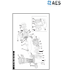
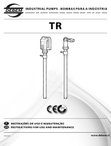
3. APPLICATIONS AND USE
Self-induction electric pump for swimming pools, incorporating large capacity pre-filter with high filtration capability.
Transparent, polycarbonate filter cover allowing easy observation of the inside of the pre-filter basket.
Our pumps have been developed for continuous operation and the materials used in their manufacture are subjected
to strict controls and are rigorously verified.
The machine has been designed to pump water that is free from explosive substances, with a density equivalent to 1000
Kg/m
3
and a kinematic viscosity of 1 mm
2
/s, as well as chemically non-aggressive liquids.
It has no uses other than the one previously described.
4. TECHNICAL DATA AND LIMITATIONS OF USE
Power supply voltage: Single-phase, 230 V, 50/60 Hz. See data plate
Three-phase, 230 - 400 V, 50/60 Hz.
Motor Protection: IP 55
Insulation class: Class F
MAXIMUM ENVIRONMENTAL TEMP.: +40ºC
MAXIMUM PUMPED LIQUID TEMP.: +40ºC
5.
TRANSPORT
Do not subject the products to unnecessary bumps and knocks.
When lifting and transporting the unit, use machines and tools that have been designed for this purpose, using the
pallet supplied as standard (if present).
0845 803 5581 |

16
3/
23
6. STORAGE
All the pumps should be stored in a sheltered, dry, dust-free place, with regulated air-moisture levels when possible.
The pumps are supplied in their original packaging, where they must remain until assembly.If not, keep the suction
and discharge ports closed.
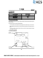
7. INSTALLATION
General
The pump should be installed as close as possible to the level of water, leaving a minimum of two metres to
the swimming pool edge in accordance with IEC publication No. 364 in a horizontal position, in order to obtain
minimum run length in suction and a reduction of load losses.
Sufficient space should be allowed for removing to pre-filter basket for cleaning and re-fitting.
The pump should be installed on a solid, very smooth surface. It is necessary to perfectly fit the pump through the two
holes provided for this purpose in the support base by means of two screws or other similar methods to prevent any
possible noise or vibration that could adversely affect the pump operation.
The pump should not be installed at a geometric height of more than 3.5 metres above the water level.
In order to obtain optimum pump self-priming, it should be installed at a maximum of 2.5 metres above the water
level.
The pump should be protected from any possible flooding and correct ventilation should be ensured, but without
risking the effects of freezing. In the case of outside installation, the pump should be protected from rain and a power
supply cable in accordance with EEC standards, type H07-Requirement Number-F (in accordance with VDE 0250)
should be installed. The pump is normally supplied without an electric power cable. In this case the pump test cables
can be seen to be cut at the outlet of the motor junction box. These cables must be replaced by a suitable electric hose
in accordance with the legislation in force in each country.
In the case of being installed a fibre housing, whether buried or half-buried, sufficient air flow should be guaranteed
to generate correct ventilation that prevents the maximum interior temperature from exceeding 40ºC.
Assembling the Piping
We recommend the installation of cut-off valves in both pump suction and impulsion so that the pump may
be removed from the installation without having to empty the whole circuit first.
The suction piping should be at least the same diameter as the pump connection, and it is also recommended that the
impulsion piping should also be the same diameter as the pump connection.
The suction piping should be assembled with a slight inclination towards the pump to prevent air pockets forming
inside.
0845 803 5581 |

17
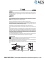
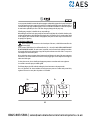
3~
230 V 400 V
1~
It is very important that both the suction and impulsion piping are independently supported and correctly fixed in place
so that the pump does not have to support their weight nor the vibration produced by the water flow though them. In
a situation where a long length of impulsion piping is used, we recommend the installation of a check valve to prevent
the water hammer produced by the return of the water causing any damage when the pump stops.
If flexible piping is employed, it should be the non-compressible type.
When making the connections to the pump, totally clean connections should always be used, with the thread in perfect
conditions and leak-tightness should be obtained only through the use of Teflon tape, (glues or similar products should
not be employed). These connection should be slowly tightened, with special care not to strip the internal thread of
the pump by over-tightening.
8.
E
LECTRICAL CONNECTION
Before carrying out any maintenance on the electrical part of the motor, it should be disconnected from the
electricity supply.
System protection should be based on a differential breaker (Ifn = 30 mA). A GOOD EARTH CONNECTION MUST
BE MADE WHENEVER POSSIBLE. The earth terminal, in particular, must be connected to the yellow/green conductor
of the supply cable. An earth conductor that is longer than the phase conductors must also be used so as to prevent it
from being the first to disconnect if pulled.
All our single-phase motors incorporate thermal protection that will disconnect the pump if the motor temperature
increases due to an overload and will then connect the electricity supply again once the temperature has dropped to
within normal levels again.
For three-phase versions, the user should provide appropriate protection in accordance with current regulations.
It is essential to connect the pump to a suitable ground.
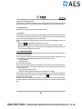
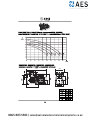
The following diagram, should be used when making the electrical connections to the pump terminals.
Use is only permitted if the electric installation has safety protection systems in accordance with personal safety
regulations in force in the country where the product is to be installed.
0845 803 5581 |

18
9. CHECKS PRIOR TO PUTTING INTO SERVICE
THE PUMP SHOULD NEVER BE ALLOWED TO OPERATE OFF LOAD
Check that the voltage and frequency of the incoming mains electricity supply correspond to those on the pump’s
specification plate.
Unscrew the transparent pre-filter cover and fill the pre-filter with water until the water level reaches the suction hole.
Replace the pre-filter cover and hand-tighten only, ensuring that it is fully tightened.
Check the pump shaft is able to freely rotate.
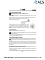
Check the that the direction of motor rotation corresponds with that indicated on the
specification plate (the fan should rotate in a CLOCKWISE DIRECTION, when viewed from
the rear of the motor. If the motor is three-phase and it is observed that it is rotating in
the opposite direction, then two of the supply phases should be inverted at the protection
panel.
10.
PUTTING INTO SERVICE
Open all valves, both suction and impulsion, and switch on the pump.
Wait a reasonable time for the pump and suction piping to self-prime. If this takes too long, then the priming
process should be repeated.
Once the pump has correctly self-primed and the pre-filter body is seen to be full of water, the motor current should
be checked and the thermal relay adjusted appropriately.
11. MAINTENANCE, DISMANTLING AND RECYCLING
The most important maintenance operation is that of keeping the pre-filter basket clean, and this filter state
check should be performed after each filtration operation and especially after bottom-cleaning. The procedure
is as follows:
Disconnect the electricity supply to the pump. Close the suction and impulsion valves to the pump. Open the pre-filter
cover, remove the basket and clean it. Once it is clean, replace it, but before closing, check the condition of the pump
body thread, pre-filter cover and the O-ring, cleaning them only with water, and where necessary apply a light coating
of neutral Vaseline.
The pump should only be dismantled by qualified personnel who hold the technical qualifications required under the
technical safety regulations of the country where the product is located.
This product and its components must be disposed of in accordance with environmental regulations. Use local public
or private waste-collection systems.
0845 803 5581 |

19
Under no circumstances should chlorine tablets be placed in the pre-filter basket.
The special key that is supplied to OPEN the pre-filter cover, should never be employed to close it.
When there is a frost risk, or when the pump is to remain off for any significant length of time, then it should
be emptied. This is accomplished by removing the two emptying plugs on the lower part of the pump body.
Apart from what has been stated above, our pumps do not require any other maintenance operations since the
bearings have been dimensioned and lubricated for life.
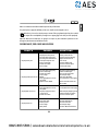
POSSIBLE FAULTS, THEIR CAUSES AND SOLUTIONS
• The pump will not prime
• The pump has not been primed
• Air entering by the suction piping
• Air entering via the mechanical seal
• Incorrectly closed pre-filter cover
• Excessive suction height
• Inverted motor rotation
• Incorrect voltage
• Air entering by the suction piping.
• Excessive suction height.
• Inverted motor rotation.
• Incorrect voltage.
• Blocked
• Suction piping diameter is less than
that required.
• Impulsion closed or blocked.
• Suction piping diameter is less than
that required.
• The pump or piping has not been
correctly secured.
• Inverted motor rotation
• Lack of mains supply.
• Breaker operation.
• Incorrect voltage.
• Motor jammed.
• Fill the pre-filter with water.
• Check the connections and piping.
• Replace the mechanical seal.
• Close correctly.
• Install at a suitable height.
• Invert two of the motor phases.
• Check the plate voltage.
• Check the connections and piping.
• Install at a suitable height.
• Invert two of the motor phases.
• Check the plate voltage.
• Clean the pre-filter basket.
• Correctly dimension the suction piping.
• Open the valve and check the sand
filter condition.
• Correctly dimension the suction piping.
• Recheck the pump and piping securing
methods so that they are separate.
• Invert two of the motor phases
• Check the voltage and fuses.
• Check and reset breaker.
• Check the plate voltage.
• Consult the Official Technical Service.
• The pump provides a poor flow rate
• The pump makes a lot of noise
• The pump will not start
FAULTS CAUSES SOLUTIONS
0845 803 5581 |

20
12.1. SAFETY RULES
Before installing and using the product:
-Carefully read the whole of this manual
-The installation and maintenance must be carried out solely and exclusively by authorised personnel, responsible
for making the electrical connections in accordance with current safety regulations.
-The frequency converter must not be used by people with reduced physical, sensory or mental capabilitie
s,
or without the due experience or knowledge, except if a person responsible for their safety has explained the
instructions and supervised their operation of their frequency converter.
-Do not let children play with the frequency converter.
-The manufacturer accepts no liability for damage caused by improper use of the product and shall not be held
responsible for damage caused by maintenance or repairs carried out by unqualified staff and/or using non-
original replacement parts.
-The use of unauthorised replacement parts, alterations of the product or improper use shall automatically render
the product guarantee null and void.
During normal operation:
-Before removing the cover of the controller for any maintenance work, ensure you disconnect the mains voltage.
-Never electrically disconnect the controller while the motor is rotating. This action may cause irreparable damage
to the electronics of the controller.
-Even if the motor is not turning (RUN LED off), the electrical supply must still be cut off for any maintenance
work.
SWIMMING POOL PUMP CONTROLLER
0845 803 5581 |

21
12.2. TECHNICAL DATA
Nominal values:
12.3. INSTALLATION AND ASSEMBLY
Before installing the pump with time controller, carefully read the whole of this manual and consult the safety rules
valid in each country.
The authorised installer must consider the following indications:
-It must be installed in a well-ventilated area, protected against moisture and direct exposure to the sun and rain.
-Before making the electrical connections, ensure the cable used to provide power to the frequency converter is
not live.
-The electric power cables to the controller must be of the correct size for the nominal consumption of the pump
and the length of cable required.
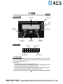
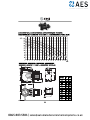
12.4. ELECTRICAL CONNECTIONS
Output pump
(220V – 16A max.)
External intakeChlorinator outletLight outlet
Power supply
(220V – 50/60Hz)
0845 803 5581 |

22
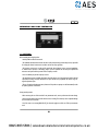
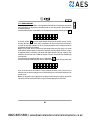
12.5. SCREEN FORMAT
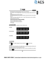
12.6. MAIN SCREEN
Main screen
Centre
selection button
Left
selection button
Manual operation
Current time
S
:
aM
7
tnu
61
t
4
re
we
Day of the week
Right
selection button
Access to the menu
Power LED
Pump
operational LED
Fault LED
Manual
lights button
12.7. OPERATION MODE
The swimming pool pump’s intelligent controller eliminates electrical panel installation requirements for the pump’s
automatic start-up, the lights, etc. in domestic installations, and includes other functions and protection elements that
a conventional electrical panel does not have.
Its main features are:
-Very intuitive QuickStart assistant for the basic configuration of the unit.
-Timer control activation/deactivation of the swimming pool pump, with three configurable daily cycles and with
the possibility to select the days of the week on which filtration is required.
-Timer control for activating the swimming pool lights, and other programmable timing applications. This function
also enables configuration of the days of the week on which the lights will be activated.
0845 803 5581 |

23
-Manual activation of the swimming pool pump, with timer stop, for occasional use.
-Manual activation of the swimming pool lights, also with timer stop, by pressing the dedicated button for this
purpose.
-Programmable output for salt chlorinator activation.
-External intake programmable by remote activation of the pump, for example from a heater, a home automation
system, etc.
-Activation of the pump’s external intake by means of a type PT-100 temperature probe (not included as
standard), which prevents frozen pipes.
-Amperimetric protection of the motor against over amperage.
-Protection of the pump against running dry (programmable).
-Alarm sound to indicate anomalies in the pump.
-Partial/total totaliser of the pump’s operating hours.
-Failure logging.
12.8. START-UP WIZARD
When starting the unit there is a QuickStart wizard, with the following sections:
a) LANGUAGE
b) DATE (DD/MM/YYYY)
c) TIME (HH:MM)
12.9. SETUP MENU
1 - LANGUAGE
Use the button to modify the language of the menus and alerts. Press to save the selection.
2 - DATE/TIME
In this submenu, the current date and time can be modified, which are very important values because the filtration and
lighting programs depend on the information provided in this point.
The value to modify will flash, making modification more intuitive. The value to be modified can be increased by
pressing the button.
F2
G
8
E
B
B
I
0
1
c
c
H
/
:
x
x
x
t
t
t
L
/
N
1
a
a
S
4
4
k
k
e
e
e
N
N
N
E
0
7
N
1
)
6
(
2
2
0845 803 5581 |

24
The changes made will not be effective until the OK button is pressed . This text is shown when editing the minutes
of the current time.
The time controller has an internal clock that together with the battery supplied guarantee that the date and time set
will not be lost if there is a power cut.
3 - FILTRATION
In this submenu, the parameters and times referred to in the pump’s filtration times can be set.
On the first submenu selection screen, set the days the filtration is required to be active. The filtration options available
are Monday to Sunday (every day of the week) Monday to Friday, only Saturday and Sunday or only Friday and Satur-
day. Filtration can also be completely deactivated.
Press the button to modify the selection. Press to confirm.
If FILTRATION OFF is selected, configuration of the remaining parameters will not continue.
If any of the other ranges of filtration days are selected, the process will continue to the selection of daily filtration
cycles. From 1 to 3 daily filtration cycles can be selected in this screen, which can be modified with the button.
Once the daily filtration cycles have been selected, in the following screens start time and the filtration time of each cycle
individually, up to a maximum filtration time of 12 hours per cycle.
4 - AMPERAGE
Access this submenu to adjust the motor’s nominal consumption.
Use the button to increase the motor’s nominal consumption in increments of a decimals of an ampere, up to
10% above the nominal consumption of the pump, aiming to protect the electric motor.
Press to save the selection. Press to exit without changing the value.
Within this submenu also we have the option to enable detection against dry running.
5 - LIGHTING
This is the submenu for editing the automatic activation of the swimming pool lights, if this automation is required.
By default the lighting programme is deactivated, although it can be activated in a very similar way to adjusting the
filtration cycles in submenu 3. FILTRATION.
On the first screen, select the days on which to activate automatic lighting of the swimming pool, selecting from the
options of Monday to Sunday, Monday to Friday, Saturday and Sunday and Friday and Saturday. Press to modify
the selection. Press to save the selection.
On the following screens set the start time for the lighting activation and the lighting time required, up to a maximum
of 12 hours.
F2
F2
F2
F2 F1
0845 803 5581 |

25
6 - HISTORY
In this submenu, merely informative, record is shown of the latest alarms, if any, due to motor current, or detection that
the pump is running dry. If there is more than one, modify the viewing by pressing .
The information is presented in the following format:
XX-DD/MM/YY-##
Where:
XX = type of alert (OL for overcurrent, DR for running dry)
DD/MM/YY = Day/Month/Year of alert
## = Number of alert on the same day
7 - MAINTENANCE
The time controller can advise when cleaning the basket in the pump is recommended as well as when it is recommen-
ded to clean the sand filter.
The alerts, if they are active, simply show a message on the screen, which can be reset.
Warnings can be adjusted individually, indicating how frequently, in days, we want to be warned regarding the cleaning
of the basket or filter, as the case may be. If they are active, they will simply show a message on the screen accompanied
by a blinking light ALARM. These warnings are only informative, with the aim of helping us to carry out the general
maintenance tasks of the filtration system.
We will also find the function SKIMMING, disabled by default, which allows us to select how frequently, in hours, the
pump will be activated for a few minutes. The operating time once these hours have been completed is 3 minutes. When
this time has passed, the programmed hours will be counted once again and the pump will be activated for 3 minutes,
and so on. This function is very useful in swimming pools where waste often falls onto the surface of the water, such as
leaves from trees, insects, etc...
8 - METERS
Informative screens that show the total count of partial operating hours (press to reset), and also a totaliser of
the pump’s general operating hours (not resettable).
Press to select the total or partial viewing of the pump’s operating hours.
9 - INTAKE/OUTPUT
The external intake as well as the relay output can be activated in this submenu (deactivated by default). Press to
activate/deactivate.
If the external intake is enabled, the pump will automatically start if active contact is detected, and will deactivate when
contact is deactivated. Activation by active contact depends on programming in section 3. FILTRATION. Deactivation
by deactivated contact takes into account the programming in section 3. FILTRATION to decide whether the pump is
in a programmed filtering cycle or not.
This intake also enables the remote activation/deactivation of the pump through a PT-100 type temperature probe.
In this case, the system decides, depending on the temperature recorded by the censor, the activation and deactivation
time of the pump, from running for 1 minute and stopped for 59 minutes at +3ºC up to a maximum of 55 minutes
running per 5 minutes stopped at very low temperatures (-30ºC). In this extreme range of temperatures, activation and
F2
F2
0845 803 5581 |

26
F2
deactivation are calculated automatically.
The pump output, if it is enabled, will activate the relay marked as chlorinator when the pump is activated and
deactivated. This contact can be used to enable operation of a salt chlorinator or to remotely control the pump status.
10 - VERSION DE SOFTWARE
An informative screen showing the software version of the time controller.
11 - FACTORY RESET
El último submenú de los ajustes permite el reseteo total de la configuración del controlador. A través de una pregunta
The last submenu in configurations enables a total reset of the configuration of the controller. Through a question, the
user can recover the factory configuration and start the start-up wizard.
The factory reset eliminate all settings made except for the alert history and the total operating hour counter on the
pump.
Note 1: The button is disabled if the configuration menu is active.
Note 2: If no selection is made in the configuration menu, the stand-by screen will return after 15 seconds.
Note 3: The values changed in the start-up wizard as well as in the configuration menu will be stored in case of
power cut, therefore reconfiguration is not required.
12.10. WARNING MANAGEMENT
During normal operation of the time controller there may be alerts which are mostly merely informative, and only in
some cases may also stop the pump.
There are luminous and acoustic type alerts. The luminous only alerts may be considered a warning, but in no case
involve modification to the normal operation of the controller. These alerts may occur due to:
-Dirty pump basket alert
-Dirty sand filter alert
These alerts can be reset manually.
There are other types of alerts that may be considered alarms, and the luminous alert will be accompanied by an
acoustic alert. The acoustic alert is not continuous, and the amount of time it sounds will depend on the time the alert
is active. These alarms are:
-Excess ammeter consumption of the motor
-Detection of the pump is operating without water (if the configurations are activated)
These two alarms are self-resettable, up to a point which very infrequently occurs in which the pump is totally blocked,
until an authorised operator with manually reset is the fault with the button. The alerts considered alarms
generate an entry in the alert history.
Remember that only the alarm about ammeter consumption on the motor is always active and cannot be deactivated.
All the other alerts/alarms are deactivated by default and are only operative for supervision by manually activating
them.
0845 803 5581 |

27
12.11. MANUAL FUNCTIONS
The intelligent controller has, in addition to the programmable automated features for activating the pump and the
swimming pool lights, two manual functions that enable manual start of the pump as well as manual activation of
the swimming pool lights.
To manually activate the pump, from the stand-by screen select the pump timer activation submenu by pressing :
In this screen, each time is pressed, the manual activation of the pump can be selected for 2 minutes, 5 minutes,
30 minutes, 60 minutes, 2 hours, 4 hours, 8 hours or deactivation. Just select the manual time desired and after a
few seconds the pump will be activated for the set time. The pump will deactivate once the intelligent controller has
checked that the selected time has transpired.
Note: It must be pointed out that if a filtration cycle begins during manual timing of the pump, or the external
intake enables the pump for operation, the pump will not stop until the end of the manually selected time, as long as
the programme filtration is not finalised, or the external intake disables operation of the pump, respectively. It also
indicates that if the chlorinator outlet is enabled with operation of the pump, this outlet will also be activated during
manual operation.
To manually activate the swimming pool lights, there is a specific button .
The same as for manual activation of the pump, each press enables manual operating time of the lights to be selected:
In this case, the times that can be selected are 15 minutes, 30 minutes, 60 minutes, 2 hours, 4 hours, 8 hours or
deactivation. Only the manual operating time must be selected and after a few seconds the lights will activate for the
manually set time.
Note: It must be pointed out that if a lighting cycle starts during the manual timing of the lights, the pump will not
stop until the end of the manually selected time, as long as the automatic lighting time has not finalised.
-
B
L
O
I
M
G
B
H
A
TS
>
=
=
0
5
m
m
i
i
n
n
6
1
F1
F1
0845 803 5581 |

28
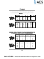
12.12. ADDITIONAL ELEMENTS
The additional elements for installation of the intelligent controller are:
-Wall mounting
-PT-100 temperature probe
a)
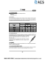
WALL MOUNTING:
The wall mounting enables the intelligent controller to be fixed to the wall in installations in which the controller
does not need to be directly connected to the motor’s terminal cover. In these situations it is very important to
ensure the correct sizing of the pump/intelligent controller electrical connection cable. The following table shows the
recommended cable selections based on the electrical power of the motor and the distance:
b) PT-100 TEMPERATURE PROBE:
The PT100 temperature probe is an element for detecting the water temperature in installations in which there is a
possibility that the pipes may freeze. To place the probe into location, it is recommended that it is as close as possible
to the swimming pool and as far away as possible from the pump room. The temperature
probe has a ¼ male threaded connection, and it is recommended to install it on th
e
pump’s pressure pipes.
It must be connected to electricity through the intake marked PT100 on the intelligent
controller. For its operation, INTAKE ON must be selected in configuration menu 9.
INTAKE/OUTPUT.
12.13. WARRANTY
The controller is guaranteed for 24 months from the purchase date. The use of original spare parts, alterations or
improper use will void the product guarantee.
12.14. DISPOSAL AND ENVIRONMENTAL ASPECTS
To remove the parts that make up the time controller, the current rules and regulations in each country in which the
product is used must be adhered to. In any case, do not dispose of polluting parts into the environment.
0845 803 5581 |

129
INFORMACION TECNICA
TECHNICAL INFORMATION
INFORMATION TECHNIQUE
TECHNISCHE INFORMATIONEN
INFORMAZIONI TECNICHE
TECHNICKÉ INFORMACE
INFORMAÇÃO TÉCNICA
TEKN
K B LG LER
13.
0845 803 5581 |


La pagina si sta caricando...
La pagina si sta caricando...
La pagina si sta caricando...
La pagina si sta caricando...
La pagina si sta caricando...
La pagina si sta caricando...
-
 1
1
-
 2
2
-
 3
3
-
 4
4
-
 5
5
-
 6
6
-
 7
7
-
 8
8
-
 9
9
-
 10
10
-
 11
11
-
 12
12
-
 13
13
-
 14
14
-
 15
15
-
 16
16
-
 17
17
-
 18
18
-
 19
19
-
 20
20
-
 21
21
-
 22
22
-
 23
23
-
 24
24
-
 25
25
-
 26
26


AES Saci Smart Winner Installation and Maintenance Manual
- Tipo
- Installation and Maintenance Manual
- Questo manuale è adatto anche per
in altre lingue
- English: AES Saci Smart Winner
Altri documenti
-
Astralpool CTX Series Istruzioni per l'uso
-
Bestway Chlorinator Manuale del proprietario
-
Davey SilensorPRO SP400BT Installation And Operating Instructions Manual
-
 Viron P600 eVo Istruzioni per l'uso
-
-
Davey DSF250CE Istruzioni per l'uso
-
Gre PP201 Guida utente
-
 Debem TR Series Instructions For Use And Maintenance Manual
-
 Pentair, Inc. INTELLIFLO VS-3050 Manuale utente
-
Jacuzzi PREMIUM J-270 Manuale del proprietario


