Asus ROG MAXIMUS Z690 FORMULA Manuale utente
- Categoria
- Schede madri
- Tipo
- Manuale utente

Motherboard
ROG
MAXIMUS
Z690
FORMULA

ii
E21832
Revised Edition V3
March 2023
Copyright © 2023 ASUSTeK COMPUTER INC. All Rights Reserved.
No part of this manual, including the products and software described in it, may be reproduced,
transmitted, transcribed, stored in a retrieval system, or translated into any language in any form or by
any means, except documentation kept by the purchaser for backup purposes, without the express
written permission of ASUSTeK COMPUTER INC. (“ASUS”).
Product warranty or service will not be extended if: (1) the product is repaired, modified or altered, unless
such repair, modification of alteration is authorized in writing by ASUS; or (2) the serial number of the
product is defaced or missing.
ASUS PROVIDES THIS MANUAL “AS IS” WITHOUT WARRANTY OF ANY KIND, EITHER EXPRESS
OR IMPLIED, INCLUDING BUT NOT LIMITED TO THE IMPLIED WARRANTIES OR CONDITIONS OF
MERCHANTABILITY OR FITNESS FOR A PARTICULAR PURPOSE. IN NO EVENT SHALL ASUS, ITS
DIRECTORS, OFFICERS, EMPLOYEES OR AGENTS BE LIABLE FOR ANY INDIRECT, SPECIAL,
INCIDENTAL, OR CONSEQUENTIAL DAMAGES (INCLUDING DAMAGES FOR LOSS OF PROFITS,
LOSS OF BUSINESS, LOSS OF USE OR DATA, INTERRUPTION OF BUSINESS AND THE LIKE),
EVEN IF ASUS HAS BEEN ADVISED OF THE POSSIBILITY OF SUCH DAMAGES ARISING FROM
ANY DEFECT OR ERROR IN THIS MANUAL OR PRODUCT.
SPECIFICATIONS AND INFORMATION CONTAINED IN THIS MANUAL ARE FURNISHED FOR
INFORMATIONAL USE ONLY, AND ARE SUBJECT TO CHANGE AT ANY TIME WITHOUT NOTICE,
AND SHOULD NOT BE CONSTRUED AS A COMMITMENT BY ASUS. ASUS ASSUMES NO
RESPONSIBILITY OR LIABILITY FOR ANY ERRORS OR INACCURACIES THAT MAY APPEAR IN
THIS MANUAL, INCLUDING THE PRODUCTS AND SOFTWARE DESCRIBED IN IT.
Products and corporate names appearing in this manual may or may not be registered trademarks or
copyrights of their respective companies, and are used only for identification or explanation and to the
owners’ benefit, without intent to infringe.

iii
Contents
Safety information ....................................................................................................... v
About this guide ......................................................................................................... vi
ROG MAXIMUS Z690 FORMULA specifications summary .................................... vii
Package contents ..................................................................................................... xiii
Installation tools and components ......................................................................... xiv
Chapter 1: Product Introduction
1.1 Before you proceed ...................................................................................1-1
1.2 Motherboard layout ....................................................................................1-2
Chapter 2: Basic Installation
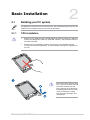
2.1 Building your PC system ...........................................................................2-1
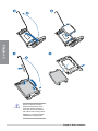
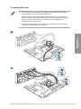
2.1.1 CPU installation...........................................................................2-1
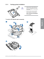
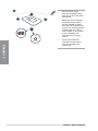
2.1.2 Cooling system installation..........................................................2-3
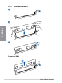
2.1.3 DIMM installation.........................................................................2-6
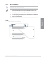
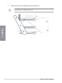
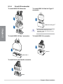
2.1.4 M.2 installation ............................................................................2-7
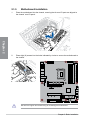
2.1.5 Motherboard installation ............................................................2-18
2.1.6 ATX power connection .............................................................. 2-19
2.1.7 SATA device connection ........................................................... 2-21
2.1.8 Front I/O connector ...................................................................2-22
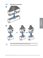
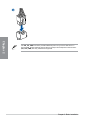
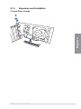
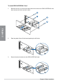
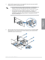
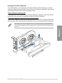
2.1.9 Expansion card installation .......................................................2-23
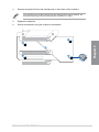
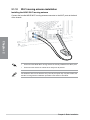
2.1.10 Wi-Fi moving antenna installation ............................................. 2-28
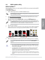
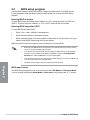
2.2 BIOS update utility ................................................................................... 2-29
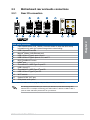
2.3 Motherboard rear and audio connections .............................................2-31
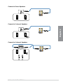
2.3.1 Rear I/O connection .................................................................. 2-31
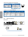
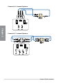
2.3.2 Audio I/O connections ............................................................... 2-32
2.4 Starting up for the first time ....................................................................2-35
2.5 Turning off the computer ........................................................................2-35
Chapter 3: BIOS and RAID Support
3.1 Knowing BIOS ............................................................................................3-1
3.2 BIOS setup program ..................................................................................3-2
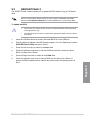
3.3 ASUS EZ Flash 3 ........................................................................................3-3
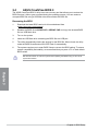
3.4 ASUS CrashFree BIOS 3 ............................................................................3-4
3.5 RAID configurations ..................................................................................3-5

iv
Appendix
Q-Code table ............................................................................................................ A-1
Notices .................................................................................................................... A-5
Warranty ................................................................................................................. A-12
ASUS contact information .................................................................................... A-14
Service and Support ............................................................................................. A-14

v
Safety information
Electrical safety
• To prevent electrical shock hazard, disconnect the power cable from the electrical
outlet before relocating the system.
• When adding or removing devices to or from the system, ensure that the power cables
for the devices are unplugged before the signal cables are connected. If possible,
disconnect all power cables from the existing system before you add a device.
• Before connecting or removing signal cables from the motherboard, ensure that all
power cables are unplugged.
• Seek professional assistance before using an adapter or extension cord. These
devices could interrupt the grounding circuit.
• Ensure that your power supply is set to the correct voltage in your area. If you are not
sure about the voltage of the electrical outlet you are using, contact your local power
company.
• If the power supply is broken, do not try to fix it by yourself. Contact a qualified service
technician or your retailer.
Operation safety
• Before installing the motherboard and adding devices on it, carefully read all the
manuals that came with the package.
• Before using the product, ensure all cables are correctly connected and the power
cables are not damaged. If you detect any damage, contact your dealer immediately.
• To avoid short circuits, keep paper clips, screws, and staples away from connectors,
slots, sockets and circuitry.
• Avoid dust, humidity, and temperature extremes. Do not place the product in any area
where it may become wet.
• Place the product on a stable surface.
• If you encounter technical problems with the product, contact a qualified service
technician or your retailer.
• Your motherboard should only be used in environments with ambient temperatures
between 0°C and 40°C.

vi
About this guide
This user guide contains the information you need when installing and configuring the
motherboard.
How this guide is organized
This guide contains the following parts:
• Chapter 1: Product Introduction
This chapter describes the features of the motherboard and the new technology it
supports. It includes description of the switches, jumpers, and connectors on the
motherboard.
• Chapter 2: Basic Installation
This chapter lists the hardware setup procedures that you have to perform when
installing system components.
• Chapter 3: BIOS and RAID Support
This chapter tells how to boot into the BIOS, upgrade BIOS using the EZ Flash Utility
and support on RAID.
Where to find more information
Refer to the following sources for additional information and for product and software
updates.
1. ASUS website
The ASUS website (www.asus.com) provides updated information on ASUS hardware
and software products.
2. Optional documentation
Your product package may include optional documentation, such as warranty flyers,
that may have been added by your dealer. These documents are not part of the
standard package.
Conventions used in this guide
To ensure that you perform certain tasks properly, take note of the following symbols used
throughout this manual.
CAUTION: Information to prevent damage to the components and injuries to
yourself when trying to complete a task.
IMPORTANT: Instructions that you MUST follow to complete a task.
NOTE: Tips and additional information to help you complete a task.

vii
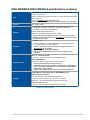
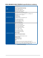
ROG MAXIMUS Z690 FORMULA specifications summary
CPU
Intel® Socket LGA1700 for 12th Gen Intel® Core™, Pentium® Gold and
Celeron® Processors*
Supports Intel® Turbo Boost Technology 2.0 and Intel® Turbo Boost Max
Technology 3.0**
* Refer to www.asus.com for CPU support list.
** Intel® Turbo Boost Max Technology 3.0 support depends on the CPU types.
Chipset Intel® Z690 Chipset
Memory
4 x DIMM, Max. 128GB, DDR5 6400+(OC) / 6200(OC) / 6000(OC) /
5800(OC) / 5600(OC) / 5400(OC) / 5200(OC) / 5000(OC) /
4800 Non-ECC, Un-buffered Memory*
Dual Channel Memory Architecture
Supports Intel® Extreme Memory Profile (XMP)
* Actual memory data rate support depends on the CPU types and DRAM
modules, for more information refer to www.asus.com for the Memory QVL
(Qualified Vendors Lists).
Graphics
1 x HDMI® port**
2 x Intel® Thunderbolt™ 4 ports (USB Type-C®) support DisplayPort
1.4 and Thunderbolt™ video outputs***
* Graphics specifications may vary between CPU types. Please refer to
www.intel.com for any updates.
** Support 4K@60Hz as specified in HDMI® 2.1.
*** VGA resolution support depends on processors’ or graphic cards’
resolution.
Expansion Slots
Intel® 12th Gen Processors*
2 x PCIe 5.0 x16 slots (supports x16 or x8/x8 modes)**
Intel® Z690 Chipset***
1 x PCIe 4.0 x16 slot (supports x4 or x4/x4 mode)***
* Please check PCIe bifurcation table in Chapter 1.
** When ROG Hyper M.2 card is installed on PCIEX16(G5)_1, PCIEX16(G5)_2
will run x8 only and if ROG Hyper M.2 card is installed on PCIEX16(G5)_2,
PCIEX16(G5)_1 will run x8 only.
*** Supports Intel® Optane Memory H Series on PCH-attached PCIe slot.
Storage
Total supports 5 x M.2 slots and 6 x SATA 6Gb/s ports*
Intel® 12th Gen Processors
M.2_1 slot (Key M), type 2242/2260/2280/22110
- Intel® 12th Gen processors support PCIe 4.0 x4 mode.
Hyper M.2_1 slot (Key M) via ROG Hyper M.2 card, type
2242/2260/2280/22110***
- Intel® 12th Gen processors support PCIe 5.0 x4 mode
(continued on the next page)

viii
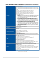
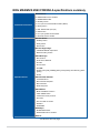
ROG MAXIMUS Z690 FORMULA specifications summary
Storage
Intel® Z690 Chipset**
M.2_2 slot (Key M), type 2242/2260/2280 (supports PCIe 3.0 x4 mode)
M.2_3 slot (Key M), type 2242/2260/2280 (supports PCIe 4.0 x4 & SATA
modes)
Hyper M.2_1 slot (Key M) via ROG Hyper M.2 card, type
2242/2260/2280/22110 (suppports PCIe 4.0 x4 mode)***
Hyper M.2_2 slot (Key M) via ROG Hyper M.2 card, type
2242/2260/2280/22110 (suppports PCIe 4.0 x4 mode)****
6 x SATA 6Gb/s ports*****
* Intel® Rapid Storage Technology supports NVMe RAID 0/1/5, SATA RAID
0/1/5/10.
** Intel® Rapid Storage Technology supports Intel® Optane Memory H
Series on PCH-attached M.2 slots.
*** When ROG Hyper M.2 card is installed on PCIEX16(G5)_1, Hyper M.2_1
slot can support PCIe 4.0 x4 mode. When ROG Hyper M.2 card is
installed on PCIEX16(G5)_2, Hyper M.2_1 slot can support PCIe 5.0 x4
mode. When ROG Hyper M.2 card is installed on PCIEX16(G4)_3, Hyper
M.2_1 and Hyper M.2_2 slots can support PCIe 4.0 x4 mode.
**** When ROG Hyper M.2 card is installed on PCIEX16(G5)_1 or
PCIEX16(G5)_2, Hyper M.2_2 slot will be disabled. When ROG Hyper M.2
card is installed on PCIEX16(G4)_3, Hyper M.2_1 and Hyper M.2_2 slots
can support PCIe 4.0 x4 mode.
***** RAID configuration and boot drives are not supported on the SATA6G_
E1-2 ports.
Ethernet 1 x Marvell® AQtion 10Gb Ethernet
ASUS LANGuard
Wireless & Bluetooth
Wi-Fi 6E
2x2 Wi-Fi 6E (802.11 a/b/g/n/ac/ax)
Supports 2.4/5/6GHz frequency band*
Bluetooth v5.2
* WiFi 6E 6GHz regulatory may vary between countries, and function will be
ready in Windows 11 or later.
USB
Rear USB (Total 12 ports)
2 x Thunderbolt™ 4 ports (2 x USB Type-C®)
7 x USB 3.2 Gen 2 ports (6 x Type-A + 1 x USB Type-C®)
3 x USB 2.0 ports (3 x Type-A)
Front USB (Total 9 ports)
1 x USB 3.2 Gen 2x2 connector (supports USB Type-C®)
2 x USB 3.2 Gen 1 headers support additional 4 USB 3.2 Gen 1 ports
2 x USB 2.0 headers support additional 4 USB 2.0 ports
Audio
ROG SupremeFX 7.1 Surround Sound High Definition Audio
CODEC ALC4082
- Impedance sense for front and rear headphone outputs
- Supports: Jack-detection, Multi-streaming, Front Panel Jack-retasking
- High quality 120 dB SNR stereo playback output and 113 dB SNR
recording input
- Supports up to 32-Bit/384 kHz playback
(continued on the next page)

ix
ROG MAXIMUS Z690 FORMULA specifications summary
Audio
Audio Features:
- SupremeFX Shielding Technology
- ESS® SABRE9018Q2C DAC/AMP
- Gold-plated audio jacks
- Rear optical S/PDIF out port
- Premium audio capacitors
Back Panel I/O Ports
2 x Thunderbolt™ 4 USB Type-C® ports
7 x USB 3.2 Gen 2 port(s) (6 x Type-A + 1 x USB Type-C®)
3 x USB 2.0 ports (3 x Type-A)
1 x HDMI® port
1 x Wi-Fi Module
1 x Marvell® AQtion 10Gb Ethernet port
5 x Gold-plated audio jacks
1 x Optical S/PDIF out port
1 x BIOS FlashBack™ button
1 x Clear CMOS button
Internal I/O connectors
Fan and Cooling related
1 x 4-pin CPU Fan header
1 x 4-pin CPU OPT Fan header
1 x 4-pin AIO Pump header
4 x 4-pin Chassis Fan headers
1 x W_PUMP+ header
1 x 2-pin Water In header
1 x 2-pin Water Out header
1 x 3-pin Water Flow header
Power related
1 x 24-pin Main Power connector
2 x 8-pin +12V Power connectors
1 x 6-pin PCIe Graphics Card connector
Storage related
3 x M.2 slots (Key M)
6 x SATA 6Gb/s ports
USB
1 x USB 3.2 Gen 2x2 connector (supports USB Type-C®)
2 x USB 3.2 Gen 1 headers support additional 4 USB 3.2 Gen 1 ports
2 x USB 2.0 headers support additional 4 USB 2.0 ports
(continued on the next page)

x
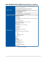
ROG MAXIMUS Z690 FORMULA specifications summary
Internal I/O connectors
Miscellaneous
3 x Addressable Gen 2 headers
1 x AURA RGB header
1 x FlexKey button
1 x 12-1 pin Front Panel Audio header (AAFP)
1 x ReTry button
1 x SPI TPM header (14-1pin)
1 x Start button
1 x 10⁻¹ pin System Panel header
1 x Thermal Sensor header
Special Features
Extreme OC Kit
- FlexKey button
- ReTry button
- Start button
Extreme Engine Digi+
- 10K Black Metallic Capacitors
- MicroFine Alloy Choke
ASUS Q-Design
- M.2 Q-Latch
- PCIe Slot Q-Release
- Q-Code
- Q-Connector
- Q-DIMM
- Q-LED (CPU [red], DRAM [yellow], VGA [white], Boot Device [yellow
green])
- Q-Slot
ASUS Thermal Solution
- CrossChill EK III
- M.2 heatsink backplate
- M.2 heatsinks
- Steel backplate
ASUS EZ DIY
- BIOS FlashBack™ button
- Clear CMOS button
- CPU Socket lever protector
- ProCool II
- Pre-mounted I/O shield
- SafeSlot
- SafeDIMM
AURA Sync
- AURA RGB header
- Addressable Gen 2 headers
OLED 2”
(continued on the next page)

xi
ROG MAXIMUS Z690 FORMULA specifications summary
Special Features
Front Panel USB 3.2 Gen 2x2 with Quick Charge 4+ Support
- Support: up to 60W charging*
- Output: 5/9/15/20V max. 3A, PPS:3.3–21V max. 3A
- Compatible with QC 4.0/3.0/2.0, PD3.0 and PPS
* To support 60W, please install the power cable to 6-pin PCIe Graphics Card
connector or can only support 27W.
ASUS HYDRANODE
- 3 x Chassis fan support* (CHA_FAN1P,CHA_FAN2P,CHA_FAN3P)*
* Visit ASUS Website for the latest compatibility list.
Software Features
ROG Exclusive Software
- ROG CPU-Z
- GameFirst VI
- Sonic Studio III + Sonic Studio Virtual Mixer + Sonic Suite Companion
- Sonic Radar III
- DTS® Sound Unbound
- BullGuard Internet Security (1-year full version)
ASUS Exclusive Software
Armoury Crate
- AIDA64 Extreme (1 year full version)
- AURA Creator
- AURA Sync
- Fan Xpert 4
- Two-Way AI Noise Cancelation
AI Suite 3
- 5-Way Optimization with AI Overclocking
TPU
EPU
DIGI+ Power Control
Turbo app
MyAsus
WinRAR
UEFI BIOS
AI Overclocking Guide
ASUS EZ DIY
- ASUS CrashFree BIOS 3
- ASUS EZ Flash 3
- ASUS UEFI BIOS EZ Mode
MemTest86
(continued on the next page)

xii
ROG MAXIMUS Z690 FORMULA specifications summary
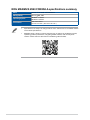
BIOS 256 Mb Flash ROM, UEFI AMI BIOS
Manageability WOL by PME, PXE
Operating System Windows® 11 64-bit
Windows® 10 64-bit
Form Factor ATX Form Factor
12 inch x 9.6 inch ( 30.5 cm x 24.4 cm )
• Specifications are subject to change without notice. Please refer to the ASUS website
for the latest specifications.
• MyASUS offers a variety of support features such as helping to troubleshoot issues,
optimizing product performance, integrating ASUS software, and recovery drive
creation. Please scan the QR Code for installation guide and FAQ.

xiii
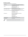
Package contents
Check your motherboard package for the following items.
Motherboard 1 x ROG MAXIMUS Z690 FORMULA motherboard
Cables
1 x ARGB RGB extension cable
1 x RGB extension cable
2 x ROG weave SATA 6G cables
4 x SATA 6Gb/s cables
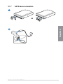
ROG HYPER M.2 CARD 1 x ROG Hyper M.2 Card with heatsink
2 x M.2 screw packages for ROG Hyper M.2 Card
Miscellaneous
1 x ASUS Wi-Fi moving antennas
1 x M.2 Rubber Package(s)
1 x Q-connector
1 x M.2 Q-Latch package(s)
2 x M.2 Q-Latch packages for M.2 backplate
1 x M.2 Rubber package
1 x ROG key chain
1 x ROG stickers
1 x ROG thank you card
Installation Media 1 x USB drive with utilities and drivers
Documentation 1 x User guide
If any of the above items is damaged or missing, contact your retailer.

xiv
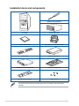
Installation tools and components
Phillips (cross) screwdriver
PC chassis Power supply unit
Intel® LGA 1700 CPU Intel® LGA 1700 compatible CPU Fan
DDR5 DIMM SATA hard disk drive
SATA optical disc drive (optional) Graphics card (optional)
M.2 SSD module (optional) 1 Bag of screws
The tools and components in the table above are not included in the motherboard
package.

ROG MAXIMUS Z690 FORMULA 1-1
Chapter 1
Product Introduction
1
Chapter 1: Product Introduction
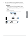
• Unplug the power cord from the wall socket before touching any component.
• Before handling components, use a grounded wrist strap or touch a safely grounded
object or a metal object, such as the power supply case, to avoid damaging them due
to static electricity.
• Hold components by the edges to avoid touching the ICs on them.
• Whenever you uninstall any component, place it on a grounded antistatic pad or in
the bag that came with the component.
• Before you install or remove any component, ensure that the ATX power supply is
switched off or the power cord is detached from the power supply. Failure to do so
may cause severe damage to the motherboard, peripherals, or components.
1.1 Before you proceed
Take note of the following precautions before you install motherboard components or
change any motherboard settings.

1-2 Chapter 1: Product Introduction
Chapter 1
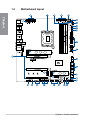
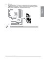
1.2 Motherboard layout

ROG MAXIMUS Z690 FORMULA 1-3
Chapter 1
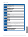
Layout contents Page
1. CPU socket 1-4
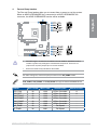
2. DIMM slots 1-5
3. Expansion slots 1-7
4. Fan and Pump headers 1-9
5. Liquid Cooling System headers 1-10
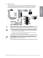
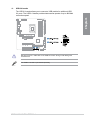
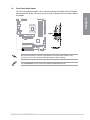
6. Power connectors 1-11
7. M.2 Slot 1-12
8. SATA 6Gb/s port 1-13
9. USB 3.2 Gen 2x2 Type-C® Front Panel connector 1-14
10. USB 3.2 Gen 1 header 1-14
11. USB 2.0 header 1-15
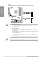
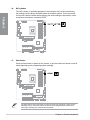
12. Addressable Gen 2 header 1-16
13. AURA RGB header 1-17
14. FlexKey button 1-18
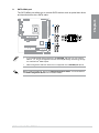
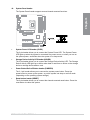
15. Front Panel Audio header 1-19
16. ReTry button 1-19
17. Start button 1-20
18. System Panel header 1-21
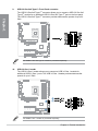
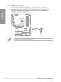
19. Thermal Sensor header 1-22
20. TPM header 1-23
21. Q-Code LED 1-24
22. Q-LEDs 1-25
23. Storage Device Activity LED 1-25
24. 8-pin Power Plug LED 1-26

1-4 Chapter 1: Product Introduction
Chapter 1
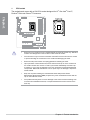
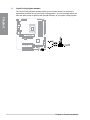
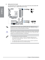
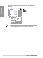
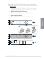
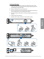
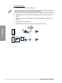
1. CPU socket
The motherboard comes with a LGA1700 socket designed for 12th Gen Intel® Core™,
Pentium® Gold and Celeron® Processors.
• Ensure that you install the correct CPU designed for LGA1700 socket only. DO NOT
install a CPU designed for other sockets on the LGA1700 socket.
• The CPU fits in only one correct orientation. DO NOT force the CPU into the socket
to prevent bending the connectors on the socket and damaging the CPU.
• Ensure that all power cables are unplugged before installing the CPU.
• Upon purchase of the motherboard, ensure that the PnP cap is on the socket and
the socket contacts are not bent. Contact your retailer immediately if the PnP cap
is missing, or if you see any damage to the PnP cap/socket contacts/motherboard
components. ASUS will shoulder the cost of repair only if the damage is shipment/
transit-related.
• Keep the cap after installing the motherboard. ASUS will process Return
Merchandise Authorization (RMA) requests only if the motherboard comes with the
cap on the LGA1700 socket.
• The product warranty does not cover damage to the socket contacts resulting from
incorrect CPU installation/removal, or misplacement/loss/incorrect removal of the
PnP cap.

ROG MAXIMUS Z690 FORMULA 1-5
Chapter 1
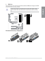
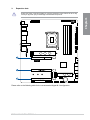
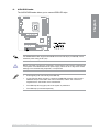
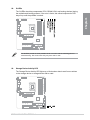
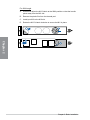
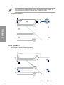
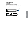
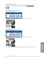
2. DIMM slots
The motherboard comes with Dual Inline Memory Modules (DIMM) slots designed for DDR5
(Double Data Rate 5) memory modules.
A DDR5 memory module is notched differently from a DDR, DDR2, DDR3, or DDR4
module. DO NOT install a DDR, DDR2, DDR3, or DDR4 memory module to the DDR5
slot.
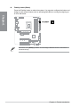
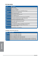
Recommended memory configurations

1-6 Chapter 1: Product Introduction
Chapter 1
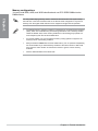
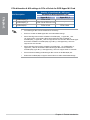
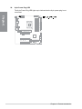
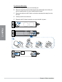
Memory configurations
You may install 8GB, 16GB, and 32GB unbuffered and non-ECC DDR5 DIMMs into the
DIMM sockets.
You may install varying memory sizes in Channel A and Channel B. The system maps
the total size of the lower-sized channel for the dual-channel configuration. Any excess
memory from the higher-sized channel is then mapped for single-channel operation.
• The default memory operation frequency is dependent on its Serial Presence Detect
(SPD), which is the standard way of accessing information from a memory module.
Under the default state, some memory modules for overclocking may operate at a
lower frequency than the vendor-marked value.
• For system stability, use a more efficient memory cooling system to support a full
memory load or overclocking condition.
• Always install the DIMMS with the same CAS Latency. For an optimum compatibility,
we recommend that you install memory modules of the same version or data code
(D/C) from the same vendor. Check with the vendor to get the correct memory
modules.
• Visit the ASUS website for the latest QVL.
La pagina si sta caricando...
La pagina si sta caricando...
La pagina si sta caricando...
La pagina si sta caricando...
La pagina si sta caricando...
La pagina si sta caricando...
La pagina si sta caricando...
La pagina si sta caricando...
La pagina si sta caricando...
La pagina si sta caricando...
La pagina si sta caricando...
La pagina si sta caricando...
La pagina si sta caricando...
La pagina si sta caricando...
La pagina si sta caricando...
La pagina si sta caricando...
La pagina si sta caricando...
La pagina si sta caricando...
La pagina si sta caricando...
La pagina si sta caricando...
La pagina si sta caricando...
La pagina si sta caricando...
La pagina si sta caricando...
La pagina si sta caricando...
La pagina si sta caricando...
La pagina si sta caricando...
La pagina si sta caricando...
La pagina si sta caricando...
La pagina si sta caricando...
La pagina si sta caricando...
La pagina si sta caricando...
La pagina si sta caricando...
La pagina si sta caricando...
La pagina si sta caricando...
La pagina si sta caricando...
La pagina si sta caricando...
La pagina si sta caricando...
La pagina si sta caricando...
La pagina si sta caricando...
La pagina si sta caricando...
La pagina si sta caricando...
La pagina si sta caricando...
La pagina si sta caricando...
La pagina si sta caricando...
La pagina si sta caricando...
La pagina si sta caricando...
La pagina si sta caricando...
La pagina si sta caricando...
La pagina si sta caricando...
La pagina si sta caricando...
La pagina si sta caricando...
La pagina si sta caricando...
La pagina si sta caricando...
La pagina si sta caricando...
La pagina si sta caricando...
La pagina si sta caricando...
La pagina si sta caricando...
La pagina si sta caricando...
La pagina si sta caricando...
La pagina si sta caricando...
La pagina si sta caricando...
La pagina si sta caricando...
La pagina si sta caricando...
La pagina si sta caricando...
La pagina si sta caricando...
La pagina si sta caricando...
La pagina si sta caricando...
La pagina si sta caricando...
La pagina si sta caricando...
La pagina si sta caricando...
La pagina si sta caricando...
La pagina si sta caricando...
La pagina si sta caricando...
La pagina si sta caricando...
La pagina si sta caricando...
La pagina si sta caricando...
-
 1
1
-
 2
2
-
 3
3
-
 4
4
-
 5
5
-
 6
6
-
 7
7
-
 8
8
-
 9
9
-
 10
10
-
 11
11
-
 12
12
-
 13
13
-
 14
14
-
 15
15
-
 16
16
-
 17
17
-
 18
18
-
 19
19
-
 20
20
-
 21
21
-
 22
22
-
 23
23
-
 24
24
-
 25
25
-
 26
26
-
 27
27
-
 28
28
-
 29
29
-
 30
30
-
 31
31
-
 32
32
-
 33
33
-
 34
34
-
 35
35
-
 36
36
-
 37
37
-
 38
38
-
 39
39
-
 40
40
-
 41
41
-
 42
42
-
 43
43
-
 44
44
-
 45
45
-
 46
46
-
 47
47
-
 48
48
-
 49
49
-
 50
50
-
 51
51
-
 52
52
-
 53
53
-
 54
54
-
 55
55
-
 56
56
-
 57
57
-
 58
58
-
 59
59
-
 60
60
-
 61
61
-
 62
62
-
 63
63
-
 64
64
-
 65
65
-
 66
66
-
 67
67
-
 68
68
-
 69
69
-
 70
70
-
 71
71
-
 72
72
-
 73
73
-
 74
74
-
 75
75
-
 76
76
-
 77
77
-
 78
78
-
 79
79
-
 80
80
-
 81
81
-
 82
82
-
 83
83
-
 84
84
-
 85
85
-
 86
86
-
 87
87
-
 88
88
-
 89
89
-
 90
90
-
 91
91
-
 92
92
-
 93
93
-
 94
94
-
 95
95
-
 96
96


Asus ROG MAXIMUS Z690 FORMULA Manuale utente
- Categoria
- Schede madri
- Tipo
- Manuale utente
in altre lingue
Documenti correlati
-
Asus PRIME B760M-A-CSM Manuale utente
-
Asus PRIME H770-PLUS Manuale utente
-
Asus ProArt B760-CREATOR Manuale utente
-
Asus E1600WK Guida utente
-
Asus PRIME H610M-D Manuale utente
-
-
Asus Pro WS W790-ACE Manuale utente
-
-
Asus P12R-M/10G-2T Manuale utente
-
