Optika B-380 Series Manuale utente
- Categoria
- Telescopi
- Tipo
- Manuale utente


Page 3
Introduction to phase contrast
Unstained specimens that do not absorb light are called phase objects because they slightly alter the phase of
the light diffracted by the specimen, usually by retarding such light approximately 1/4 wavelength as compared
to the undeviated direct light passing through or around the specimen unaffected. Unfortunately, our eyes as well
as camera lm, are unable to detect these phase differences. To reiterate, the human eye is sensitive only to the
colors of the visible spectrum (variations in light frequency) or to differing levels
of light intensity (variations in wave amplitude).
In phase specimens, the direct zeroth order light passes through or around the specimen undeviated. However,
the light diffracted by the specimen is not reduced in amplitude as it is in a light-absorbing object, but is slowed
by the specimen because of the specimen’s refractive index or thickness (or both). This diffracted light, lagging
behind by approximately 1/4 wavelength, arrives at the image plane out of step (also termed out of phase) with
the undeviated light but, in interference, essentially undiminished in intensity. The result is that the image at the
eyepiece level is so lacking in contrast as to make the details almost invisible.
Zernike succeeded in devising a method–now known as Phase Contrast microscopy–for making unstained,
phase objects yield contrast images as if they were amplitude objects.
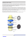
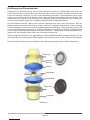
A schematic illustration of the basic phase contrast microscope conguration is illustrated in Figure 1.
Phase
Ring
Deflected
light
Objective
Specimen
Condenser
Annular
Ring
Light from
source
Figure 1

Page 4
Amplitude objects show excellent contrast when the diffracted and direct light are out of step (display a phase
difference) by 1/2 of a wavelength. Zernike’s method was to speed up the direct light by 1/4 wavelength so that
the difference in wavelength between the direct and deviated light for a phase specimen would now be 1/2
wavelength. As a result, the direct and diffracted light arriving at the image level of the eyepiece would be able to
produce destructive interference. Such a procedure results in the details of the image appearing darker against
a lighter background. This is called positive phase contrast (see Figure 2).
Another possible course is to arrange to slow down the direct light by 1/4 wavelength so that the diffracted light
and the direct light arrive at the eyepiece in step and can interfere constructively. This arrangement results in a
bright image of the details of the specimen on a darker background, and is called negative contrast (see Figure
3).
The accessories needed for phase contrast work are a substage phase contrast condenser equipped with an-
nuli and a set of phase contrast objectives, each of which has a phase plate installed. The phase outt, usually
includes a green lter (to increase the resolution) and a phase telescope (to center the annuli).
Phase microscopy techniques are particularly useful with specimens that are thin and scattered in the eld of
view. There are some limitations of phase contrast microscopy:
• Phase images are usually surrounded by halos around the outlines of details. Such halos are optical arti-
facts, which sometimes obscure the boundaries of details.
• The phase annuli do limit the working numerical aperture of the optical system to a certain degree,
thus reducing resolution.
• Phase contrast does not work well with thick specimens because of shifts in phase occur from areas slightly
below or slightly above the plane that is in focus.
• Phase images appear gray if white light is used and green if a green lter is used.
Figure 2 Figure 3

Page 5
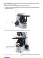
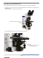
Setup on B-380 microscopes
In order to use phase contrast on a B-380 series microscope, follow these steps:
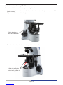
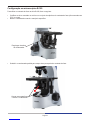
• Make sure that a phase contrast objectives set is mounted on the nosepiece (phase contrast objectives are
marked with “PH” writing).
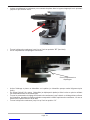
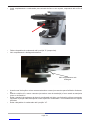
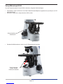
• Lower the condenser using the knob:
• Replace the standard brighteld condenser with the phase contrast condenser:
Condenser height
adjustement knob
Loosen these screws
and pull the condenser
out

Page 6
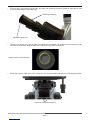
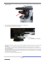
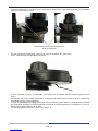
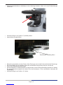
• Fully insert the phase contrast condenser into the holder, pushing it until it is well inserted:
• Rotate the condenser annuli disc to the “0” position (brighteld).
• Completely open the aperture diaphragm:
• Turn on the light and put a sample slide on the stage (an opaque specimen will make alignment easier).
• Using the 10x objective, center your sample (moving the stage) and focus using the coarse and ne focus
knobs.
• Rotate the condenser height adjustment knob until you obtain a uniform white illumination on the sample.
Important: the optimal position corresponds to the top lens of the condenser 1-2mm below the bottom side
of the slide.
• Rotate the condenser annuli disc to the “10” position.
Completely open this diaphragm

Page 7
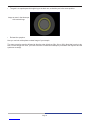
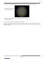
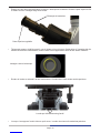
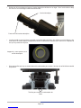
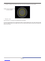
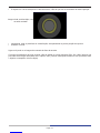
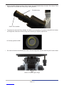
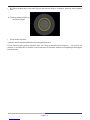
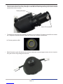
Image as seen in the telescope
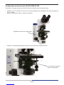
Levers for phase ring alignment
• Take one of the eyepieces out of the tube, and insert the centering telescope. Rotate its upper part in order
to view a sharp image of the phase ring:
• Typically, you have to see a pair of rings: one brighter and one darker. The bright one is the image of the an-
nulus on the condenser, while the dark one is the phase ring inside the objective:
• Rotate the levers on both sides of the condenser. You will notice that the bright ring will change its position:
Centering telescope
Adjustable upper part

Page 8
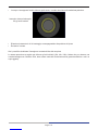
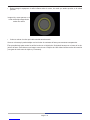
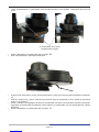
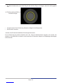
• The goal is to superimpose this bright ring to the dark one, so that they are in the same position:
• Reinsert the eyepiece.
Now you can look at the phase contrast image of your sample.
The same procedure must be followed to align the other objectives (20x, 40x or 100x). Note that in order to ob-
tain a correct image with 100x, you have to use the oil immersion technique (oil between the objective and the
specimen coverslip).
Image as seen in the telescope,
with centred rings.

Page 9
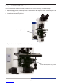
Setup on B-500 B-800 B-1000 microscopes
In order to use phase contrast on a B-500, B-800 or B-1000 series microscope, follow these steps:
• Make sure that a phase contrast objectives set is mounted on the nosepiece (phase contrast objectives are
marked with “PH” writing).
• Lower the condenser using the knob:
• Replace the standard brighteld condenser with the phase contrast condenser:
Condenser height adjustement knob
Loosen the lock screw and pull the
condenser out

Page 10
• Fully insert the phase contrast condenser into the holder, pushing it until it is well inserted:
• Rotate the condenser annuli disc to the “BF” position (brighteld).
• Completely open the aperture diaphragm:
• Turn on the light and put a sample slide on the stage (an opaque specimen will make alignment easier).
• Using the 10x objective, center your sample (moving the stage) and focus using the coarse and ne focus
knobs.
• Rotate the condenser height adjustment knobs until you obtain a uniform white illumination on the sample.
Important: the optimal position corresponds to the top lens of the condenser 1-2mm below the bottom side
of the slide.
• Rotate the condenser annuli disc to the “10” position.
Condenser must fully enter into its guide

Page 11
• Take one of the eyepieces out of the tube, and insert the centering telescope. Loosen the screw of the tele-
scope and move its upper part in order to view a sharp image of the phase ring, then lock the screw:
• Typically, you have to see a pair of rings: one brighter and one darker. The bright one is the image of the an-
nulus on the condenser, while the dark one is the phase ring inside the objective:
• Press both the long screws on the sides of the condenser and then slowly turn them until you notice that the
bright ring changes its position:
Telescope’s screw
Adjustable upper part
Image as seen in the telescope

Page 12
• The goal is to superimpose this bright ring to the dark one, so that they are in the same position:
• Release the centering screws slowly, guiding them to the rest position.
• Reinsert the eyepiece.
Now you can look at the phase contrast image of your sample.
The same procedure must be followed to align the other objectives (20x, 40x or 100x). Note that in order to ob-
tain a correct image with 100x, you have to use the oil immersion technique (oil between the objective and the
specimen coverslip).
Image as seen in the telescope,
with centred rings.


Pagina 15
Introduzione al contrasto di fase
I preparati senza alcuna colorazione che non assorbono luce sono chiamati “oggetti di fase”, poiché alterano
leggermente la fase della luce che li attraversa, ritardandola tipicamente di 1/4 di lunghezza d’onda rispetto alla
luce diretta che passa non deviata intorno al campione. Sfortunatamente i nostri occhi, come i sensori delle te-
lecamere, non sono in grado di apprezzare queste differenze di fase. L’occhio umano è sensibile solo ai colori
dello spettro visibile (variazioni nella frequenza della luce) o a differenti livelli di intensità luminosa (variazioni
nell’ampiezza dell’onda luminosa).
Negli oggetti di fase, l’ “ordine zero” della luce passa attraverso o intorno al campione non essendo deviata. La
luce diffratta dall’oggetto non è ridotta in ampiezza (come nei campioni opachi), ma è rallentata (ritardo di fase)
in funzione dell’indice di rifrazione e dello spessore del campione. Questa luce diffratta, rallentata di circa 1/4 di
lunghezza d’onda, arriva sul piano dell’immagine fuori fase rispetto alla luce diretta non deviata, ma essenzial-
mente non ridotta in intensità. Il risultato è che l’immagine a livello dell’oculare manca di contrasto e i dettagli del
campione sono quasi invisibili.
Zernike ebbe successo nel mettere a punto un metodo, ora noto come Microscopia a Contrasto di Fase, che
consente di ottenere immagini contrastate di oggetti di fase trasparenti, come se fossero campioni opachi.
Un’illustrazione schematica della congurazione di un microscopio a contrasto di fase è mostrata in gura 1.
Anello di Fase
Luce
deviata
Obiettivo
Vetrino porta preparato
Condensatore
Diaframma
ad anello
Sorgente luminosa
Figura 1

Pagina 16
Il campione mostra un eccellente contrasto quando la luce diffratta e la luce diretta (non deviata) sono sfasate
di 1/2 di lunghezza d’onda. Il metodo di Zernike consiste nello sfasare ulteriormente anche la luce diretta di 1/4
di lunghezza d’onda, in modo che la differenza tra luce diffratta e diretta sia proprio 1/2 di lunghezza d’onda.
Come risultato, le due componenti di luce producono un’interferenza distruttiva sul piano immagine dell’oculare.
Questa procedura produce un’immagine con dettagli più scuri su un fondo più chiaro. Questa tipologia è detta
contrasto di fase positivo (gura 2).
Una seconda variante consiste nello sfasare la luce diretta sempre di 1/4 di lunghezza d’onda ma in modo che
arrivi in fase sul piano immagine con la luce diffratta, causando quindi interferenza costruttiva. Questa procedura
produce un’immagine con dettagli più chiari su un fondo più scuro. Questa tipologia è detta contrasto di fase
negativo (gura 3).
Gli accessori richiesti per il funzionamento in contrasto di fase sono un condensatore da porre sotto il tavo- lino,
equipaggiato con diaframmi ad anello, e un set di obiettivi per contrasto di fase, ciascuno dotato di una lamina
di fase ad anello. La dotazione include inoltre un ltro verde (per incrementare la risoluzione) e un telescopio di
centratura (per centrare gli anelli).
Le tecniche di microscopia di fase sono particolarmente utili con campioni sottili e distribuiti sul campo visivo. Vi
sono alcune limitazioni in tale tecnica:
• Le immagini di fase sono solitamente affette da aloni intorno ai bordi dei dettagli. Questi aloni sono artefatti
ottici, che possono oscurare talvolta le frontiere tra dettagli adiacenti.
• Gli anelli di fase limitano l’apertura numerica del sistema ottico, riducendo (comunque in minimo grado) la
risoluzione.
• Il contrasto di fase non funziona al meglio con campioni spessi, in quanto le variazioni di fase av- vengono
in zone poco al di sopra o al di sotto del piano di messa a fuoco.
• Le immagini di fase appaiono grigie quando viene usata una luce bianca, e verdi quando viene inserito il
ltro verde.
Figura 2 Figura 3

Pagina 17
Set-up su microscopi B-380
Per utilizzare il contrasto di fase sulla serie B-380, seguire questi passi:
• Assicurarsi di aver montato sul revolver un set di obiettivi a contrasto di fase (sono marcati con “PH” sul
corpo).
• Abbassare il condensatore usando l’apposita manopola:
• Sostituire il condensatore standard per campo chiaro con quello per contrasto di fase:
Regolazione altezza
condensatore
Allentare queste viti ed
estrarre il condensatore

Pagina 18
• Inserire completamente il condensatore per contrasto di fase nel proprio supporto, spingendolo a ne corsa:
• Ruotare la ghiera del condensatore no alla posizione “0” (campo chiaro).
• Aprire completamente il diaframma di apertura:
• Accendere l’illuminazione e porre un campione sul tavolino (un campione opaco faciliterà l’allineamento).
• Usando l’obiettivo 10x, centrare il campione (muovendo il tavolino traslatore) e mettere a fuoco usando le
manopole macro- e micrometrica.
• Ruotare la manopola di regolazione dell’altezza condensatore no ad ottenere un’illuminazione uniforme sul
campione. Importante: la posizione ottimale corrisponde alla lente superiore del condensatore 1-2 mm sotto
la faccia inferiore del vetrino.
• Ruotare la ghiera del condensatore no alla posizione “10”.
Aprire completamente questo
diaframma

Pagina 19
Immagine vista nel telescopio
Levette per l’allineamento degli anelli
• Estrarre uno dei due oculari dalla testa, e inserire il telescopio di centratura. Ruotare la parte superiore no
a mettere a fuoco l’immagine degli anelli di fase:
• Tipicamente saranno visibili due anelli: uno più chiaro ed uno più scuro. Quello chiaro è l’immagine del dia-
framma ad anello del condensatore, mentre l’anello scuro rappresenta l’anello di fase dentro l’obiettivo:
• Ruotare le levette su entrambi i lati del condensatore. Si noterà che l’anello chiaro cambia posizione:
• Lo scopo è sovrapporre l’anello chiaro a quello scuro, in modo che siano nella medesima posizione:
Telescopio di centratura
Parte superiore regolabile

Pagina 20
• Reinserire l’oculare
Ora è possibile visualizzare l’immagine a contrasto di fase del campione.
La stessa procedura va seguita per allineare gli altri obiettivi (20x, 40x, 100x). Notare che per ottenere una
corretta immagine con l’obiettivo 100x, deve essere usato dell’olio da immersione (posto tra obiettivo e vetrino
copri-oggetto).
Immagine vista nel telescopio,
con gli anelli centrati
La pagina si sta caricando...
La pagina si sta caricando...
La pagina si sta caricando...
La pagina si sta caricando...
La pagina si sta caricando...
La pagina si sta caricando...
La pagina si sta caricando...
La pagina si sta caricando...
La pagina si sta caricando...
La pagina si sta caricando...
La pagina si sta caricando...
La pagina si sta caricando...
La pagina si sta caricando...
La pagina si sta caricando...
La pagina si sta caricando...
La pagina si sta caricando...
La pagina si sta caricando...
La pagina si sta caricando...
La pagina si sta caricando...
La pagina si sta caricando...
La pagina si sta caricando...
La pagina si sta caricando...
La pagina si sta caricando...
La pagina si sta caricando...
La pagina si sta caricando...
La pagina si sta caricando...
La pagina si sta caricando...
La pagina si sta caricando...
La pagina si sta caricando...
La pagina si sta caricando...
La pagina si sta caricando...
La pagina si sta caricando...
La pagina si sta caricando...
La pagina si sta caricando...
La pagina si sta caricando...
La pagina si sta caricando...
La pagina si sta caricando...
La pagina si sta caricando...
La pagina si sta caricando...
La pagina si sta caricando...
La pagina si sta caricando...
La pagina si sta caricando...
La pagina si sta caricando...
La pagina si sta caricando...
La pagina si sta caricando...
La pagina si sta caricando...
La pagina si sta caricando...
La pagina si sta caricando...
La pagina si sta caricando...
La pagina si sta caricando...
La pagina si sta caricando...
La pagina si sta caricando...
La pagina si sta caricando...
La pagina si sta caricando...
La pagina si sta caricando...
La pagina si sta caricando...
La pagina si sta caricando...
La pagina si sta caricando...
La pagina si sta caricando...
La pagina si sta caricando...
-
 1
1
-
 2
2
-
 3
3
-
 4
4
-
 5
5
-
 6
6
-
 7
7
-
 8
8
-
 9
9
-
 10
10
-
 11
11
-
 12
12
-
 13
13
-
 14
14
-
 15
15
-
 16
16
-
 17
17
-
 18
18
-
 19
19
-
 20
20
-
 21
21
-
 22
22
-
 23
23
-
 24
24
-
 25
25
-
 26
26
-
 27
27
-
 28
28
-
 29
29
-
 30
30
-
 31
31
-
 32
32
-
 33
33
-
 34
34
-
 35
35
-
 36
36
-
 37
37
-
 38
38
-
 39
39
-
 40
40
-
 41
41
-
 42
42
-
 43
43
-
 44
44
-
 45
45
-
 46
46
-
 47
47
-
 48
48
-
 49
49
-
 50
50
-
 51
51
-
 52
52
-
 53
53
-
 54
54
-
 55
55
-
 56
56
-
 57
57
-
 58
58
-
 59
59
-
 60
60
-
 61
61
-
 62
62
-
 63
63
-
 64
64
-
 65
65
-
 66
66
-
 67
67
-
 68
68
-
 69
69
-
 70
70
-
 71
71
-
 72
72
-
 73
73
-
 74
74
-
 75
75
-
 76
76
-
 77
77
-
 78
78
-
 79
79
-
 80
80


Optika B-380 Series Manuale utente
- Categoria
- Telescopi
- Tipo
- Manuale utente
in altre lingue
- English: Optika B-380 Series User manual
- français: Optika B-380 Series Manuel utilisateur
- español: Optika B-380 Series Manual de usuario
- Deutsch: Optika B-380 Series Benutzerhandbuch
Documenti correlati
Altri documenti
-
 Optika Italy B-150P Series Manuale utente
-
Celestron LCD Digital Microscope II Manuale utente
-
-
-
-
3B SCIENTIFIC PHYSICS 300 1013368 Manuale utente
-
-
