La pagina si sta caricando...

EPJcolor - Interfacce utente remote
IMPORTANTE
Leggere attentamente questo documento prima
dell’installazione, seguire tutte le avvertenze prima
dell’uso del dispositivo.
Conservare questo documento con il dispositivo per
consultazioni future.
Utilizzare il dispositivo solo seguendo le modalità
descritte in questo documento
UTILIZZO
Dispositivo utilizzato per applicazioni interne
SMALTIMENTO
Il dispositivo deve essere smaltito secondo le
normative locali in merito alla raccolta delle
apparecchiature elettriche ed elettroniche
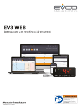
EPJcolor è un’interfaccia utente programmabile dotata di
display graco con logica di regolazione a bordo comunicazione
MODBUS master/slave.
Descrizione
Caratteristiche
24 VAC/DC - Touch screen a colori - Installazione a parete
- RS485 - USB - Orologio - Buzzer di allarme
111,4 mm
18,5 mm
76,4 mm
2,75 in
1.DIMENSIONI
Installazione a parete
1. Sganciare il guscio posteriore dal frontale con l’aiuto di
un cacciavite nell’apposita sede
2. Appoggiare il guscio posteriore alla parete in un punto
adeguato a far passare i cavi di collegamento
attraverso l’apposita apertura
3. Utilizzare le asole del guscio posteriore come guida per
eseguire 4 fori di un diametro adeguato al tassello.
Si consiglia di utilizzare tasselli diametro 5,0 mm
4. Inserire i tasselli nei fori eseguiti nella parete
5. Fissare il guscio posteriore alla parete con 4 viti.
Si consiglia di utilizzare viti a testa svasata piana
6. Eseguire il collegamento elettrico senza dare
alimentazione al dispositivo
7. Fissare il frontale del dispositivo al guscio posteriore
Sede
Frontale
Parete
Guscio posteriore
Asola
Apertura per il passaggio
dei cavi di collegamento
Cavi di
collegamento
AVVERTENZE PER L’INSTALLAZIONE
-Accertarsi che le condizioni di lavoro rientrino nei limiti
indicati nel capitolo “Dati tecnici”
-Non installare il dispositivo in prossimità di fonti
di calore, di apparecchi con forti magneti, di
luoghi soggetti alla lucemsolare diretta, di pioggia,
di umidità, di polvere eccessiva, di vibrazioni
meccaniche o scosse
-In conformità alle normative sulla sicurezza, la
protezione contro eventuali contatti con le parti
elettriche deve essere assicurata mediante una
corretta installazione; tutte le parti che assicurano la
protezione devono essere ssate in modo tale da non
poter essere rimosse senza l’aiuto di un utensile
AVVERTENZE PER I COLLEGAMENTI ELETTRICI
-Utilizzare cavi di sezione adeguata alla corrente che
li percorre
-Per ridurre eventuali disturbi elettromagnetici,
collocare i cavi di potenza il più lontano possibile
da quelli di segnale ed eseguire il collegamento a
una rete RS-485 MODBUS utilizzando un doppino
twistato
Connettore 2
Connettore 1
Micro-switch
2.COLLEGAMENTI ELETTRICI
Descrizione connettori
Connettore 1
Numero Descrizione
3
Alimentazione dispositivo (24 VAC/12... 30 VDC);
se il dispositivo è alimentato in corrente continua,
collegare il terminale negativo
4
Alimentazione dispositivo (24 VAC/12... 30 VDC);
se il dispositivo è alimentato in corrente continua,
collegare il terminale positivo
5Riferimento porta RS-485 MODBUS (GND)
6Riferimento - porta RS-485 (MODBUS B)
7Riferimento + porta RS-485 (MODBUS A)
EPJcolor - Interfacce utente remote
IMPORTANTE
Leggere attentamente questo documento prima
dell’installazione, seguire tutte le avvertenze prima
dell’uso del dispositivo.
Conservare questo documento con il dispositivo per
consultazioni future.
Utilizzare il dispositivo solo seguendo le modalità
descritte in questo documento
UTILIZZO
Dispositivo utilizzato per applicazioni interne
SMALTIMENTO
Il dispositivo deve essere smaltito secondo le
normative locali in merito alla raccolta delle
apparecchiature elettriche ed elettroniche
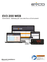
EPJcolor è un’interfaccia utente programmabile dotata di
display graco con logica di regolazione a bordo comunicazione
MODBUS master/slave.
Descrizione
Caratteristiche
24 VAC/DC - Touch screen a colori - Installazione a parete
- RS485 - USB - Orologio - Buzzer di allarme
004_EPJColor_Parete_001_0.1_AZ
111,4 mm
18,5 mm
76,4 mm
2,75 in
1.DIMENSIONI
Installazione a parete
008_EPJColor_Parete_001_0.1_AZ
1. Sganciare il guscio posteriore dal frontale con l’aiuto di
un cacciavite nell’apposita sede
2. Appoggiare il guscio posteriore alla parete in un punto
adeguato a far passare i cavi di collegamento
attraverso l’apposita apertura
3. Utilizzare le asole del guscio posteriore come guida per
eseguire 4 fori di un diametro adeguato al tassello.
Si consiglia di utilizzare tasselli diametro 5,0 mm
4. Inserire i tasselli nei fori eseguiti nella parete
5. Fissare il guscio posteriore alla parete con 4 viti.
Si consiglia di utilizzare viti a testa svasata piana
6. Eseguire il collegamento elettrico senza dare
alimentazione al dispositivo
7. Fissare il frontale del dispositivo al guscio posteriore
Sede
Frontale
Parete
Guscio posteriore
Asola
Apertura per il passaggio
dei cavi di collegamento
Cavi di
collegamento
AVVERTENZE PER L’INSTALLAZIONE
-Accertarsi che le condizioni di lavoro rientrino nei limiti
indicati nel capitolo “Dati tecnici”
-Non installare il dispositivo in prossimità di fonti
di calore, di apparecchi con forti magneti, di
luoghi soggetti alla lucemsolare diretta, di pioggia,
di umidità, di polvere eccessiva, di vibrazioni
meccaniche o scosse
-In conformità alle normative sulla sicurezza, la
protezione contro eventuali contatti con le parti
elettriche deve essere assicurata mediante una
corretta installazione; tutte le parti che assicurano la
protezione devono essere ssate in modo tale da non
poter essere rimosse senza l’aiuto di un utensile
AVVERTENZE PER I COLLEGAMENTI ELETTRICI
-Utilizzare cavi di sezione adeguata alla corrente che
li percorre
-Per ridurre eventuali disturbi elettromagnetici,
collocare i cavi di potenza il più lontano possibile
da quelli di segnale ed eseguire il collegamento a
una rete RS-485 MODBUS utilizzando un doppino
twistato
7
6
5
4
3
2
1
002_EPJColor_Parete_DescrizConnettori_001_0.1_AZ
EPJcolor
12
ON
Connettore 2
Connettore 1
Micro-switch
2.COLLEGAMENTI ELETTRICI
Descrizione connettori
Connettore 1
Numero Descrizione
3
Alimentazione dispositivo (24 VAC/12... 30 VDC);
se il dispositivo è alimentato in corrente continua,
collegare il terminale negativo
4
Alimentazione dispositivo (24 VAC/12... 30 VDC);
se il dispositivo è alimentato in corrente continua,
collegare il terminale positivo
5Riferimento porta RS-485 MODBUS (GND)
6Riferimento - porta RS-485 (MODBUS B)
7Riferimento + porta RS-485 (MODBUS A)

AVVERTENZE PER I COLLEGAMENTI ELETTRICI
-Se si utilizzano avvitatori elettrici o pneumatici,
moderare la coppia di serraggio
-Se il dispositivo è stato portato da un luogo freddo ad
un luogo caldo, l’umidità potrebbe aver condensato
all’interno; attendere circa un’ora prima di
alimentarlo
-Accertarsi che la tensione di alimentazione, la
frequenza elettrica e la potenza elettrica rientrino
nei limiti
-Scollegare l’alimentazione prima di procedere con
qualunque tipo di manutenzione
-Non utilizzare il dispositivo come dispositivo di
sicurezza
Connettore 2
Numero Descrizione
Porta USB, per la programmazione del dispositivo
Micro-switch
Numero Descrizione
1Per terminare la rete RS-485 MODBUS
Terminazione della rete RS-485 MODBUS
Per terminare la rete RS-485 MODBUS:
–Posizionare il micro-switch 2 in posizione ON
–Lasciare il micro switch 1 in posizione OFF
Il micro-switch è posizionato sul retro del dispositivo
(rimuovere prima il guscio posteriore dal frontale)
Collegamento elettrico con alimentazione indipendente
Tipo Descrizione
Scopo del dispositivo di
comando
Dispositivo di comando di
funzionamento
Costruzione del dispositivo
di comando Dispositivo elettronico incorporato
Contenitore Autoestinguente nero
Categoria di resistenza al
calore e al fuoco D
Dimensioni 111,4 x 76,4 x 18,5 mm
Metodo di montaggio del
dispositivo di comando A parete
Grado di protezione fornito
dall’involucro IP30
Metodo di connessione Morsettiere sse a vite per
conduttori no a 1 mm²
Lunghezze massime
consentite per i cavi di
collegamento
Alimentazione: 10 m
Porta RS-485 MODBUS: 1.000 m
(3.280 ft)
Temperatura di impiego -10 – 55 °C
Temperatura di
immagazzinamento -20 – 70 °C
Umidità di impiego Da 5 a 95% di umidità relativa senza
condensa
Situazione di inquinamento
del dispositivo di comando 2
Conformità
- RoHS 2011/65/CE
- WEEE 2012/19/EU
- Regolamento REACH (CE) n.
1907/2006
- RED 2014/53/UE
Alimentazione
24 VAC (±15%), 50/60 Hz (±3 Hz)
Max. 4 VA non isolata o 12... 30 VDC,
max. 2 W non isolata
(alimentazione indipendente o erogata
da un controllore)
Metodo di messa a terra del
dispositivo di comando Nessuno
Tensione impulsiva
nominale I
Categoria di sovratensione 330 V
Classe e struttura del
software A
Orologio Batteria secondaria al litio
incorporata
Deriva dell’orologio ≤ 55 s/mese a 25 °C
Autonomia della batteria
dell’orologio in mancanza
dell’alimentazione
6 mesi
Tempo di carica della
batteria dell’orologio
24 h (la batteria viene caricata
dall’alimentazione del dispositivo)
Visualizzazioni Display graco TFT touch-screen a
colori
Buzzer di allarme Incorporato
Porte di comunicazione - 1 porta RS-485 MODBUS
- 1 porta USB
3.DATI TECNICI
PRECAUTIONS FOR ELECTRICAL CONNECTION
-If using an electrical or pneumatic screwdriver,
adjust the tightening torque
-If the device has been moved from a cold to a warm
place, the humidity may have caused condensation to
form inside. Wait about an hour before switching on
the power
-Make sure that the supply voltage, electrical
frequency and power are within the set limits. See
the section TECHNICAL SPECIFICATIONS
-Disconnect the power supply before doing any type
of maintenance
-Do not use the device as safety device
Connector 2
Number Description
USB port, for programming the device.
Micro-switch
Number Description
1to terminate the RS485 Modbus network
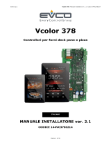
001_EPJColor_Parete_AlimentazioneIndipendente_001_0.1_AZ
GND
+
-
+
-
+
-
7
6
5
4
3
2
1
EPJcolor
12
ON
12
ON
Device with
RS-485 port
RS-485 Micro-switch
230 VAC / 24 VAC 4 VA
safety transformer
Do not supply another
device with the same
transformer.
Electricity grid
230 VAC
Insertion of the RS-485 MODBUS port termination resistor
To insert the RS-485 MODBUS port termination resistor:
–Place micro-switch 2 in position ON
–Place micro-switch 2 in position OFF
The micro-switch is at the back of the device (remove the
back shell from the front before).
Electrical connection with independent power supply
Type Description
Purpose of the control device Function controller
Construction of the control
device Built-in electronic device
Container Black, self-extinguishing
Category of heat and re
resistance D
Dimensions 111,4 x 76,4 x 18,5 mm
Mounting methods for the
control device wall mounting
Degree of protection provided
by the covering IP30
Connection method Fixed screw terminal for wires up to 1
mm² blocks
Maximum permitted length
for connection cables
Power supply: 10 m
RS-485 MODBUS port: 1,000 m (3,280
ft)
Operating temperature -10 – 55 °C
Storage temperature -20 – 70 °C
Operating humidity Relative humidity without condensate
from 5 to 95%
Pollution status of the control
device 2
Compliance
- RoHS 2011/65/CE
- WEEE 2012/19/EU
- REACH (EC) Regulation N.
1907/2006
- RED 2014/53/UE
Power supply
24 VAC (±15%), 50/60 Hz (±3 Hz), max.
4 VA not insulated or 12... 30 VDC,
max. 2 W not insulated (independent
power supply or by a controller)
Earthing methods for the
control device none
Rated impulse-withstand
voltage I
Over-voltage category 330 V
Software class and structure A
Clock Incorporated secondary lithium
battery
Clock drift ≤ 55 s/month at 25 °C
Clock battery autonomy in the
absence of a power supply 6 month
Clock battery charging time 24 h (the battery is charged by the
power supply of the device)
Displays Colour touch-screen TFT graphic
display
Alarm buzzer Built-in
Communications ports - 1 RS-485 MODBUS port
- 1 USB port
3.TECHNICAL SPECIFICATIONS
EVCO S.p.A.
Via Feltre 81, 32036 Sedico (BL) ITALY - Tel. +39 0437 8422 - Fax +39 0437 83648 - e-mail info@evco.it - web www.evco.it
Questo documento e le soluzioni in esso contenute sono proprietà intellettuale EVCO tutelata dal Codice dei diritti di proprietà Industriale (CPI). EVCO pone
il divieto assoluto di riproduzione e divulgazione anche parziale dei contenuti se non espressamente autorizzata da EVCO stessa. Il cliente (costruttore,
installatore o utente nale) si assume ogni responsabilità in merito alla congurazione del dispositivo.
EVCO non si assume alcuna responsabilità in merito ai possibili errori riportati e si riserva il diritto di apportare qualsiasi modica in qualsiasi momento senza
pregiudicare le caratteristiche essenziali di funzionalità e di sicurezza.
004980 - 00 - 0920
PRECAUTIONS FOR ELECTRICAL CONNECTION
-If using an electrical or pneumatic screwdriver,
adjust the tightening torque
-If the device has been moved from a cold to a warm
place, the humidity may have caused condensation to
form inside. Wait about an hour before switching on
the power
-Make sure that the supply voltage, electrical
frequency and power are within the set limits. See
the section TECHNICAL SPECIFICATIONS
-Disconnect the power supply before doing any type
of maintenance
-Do not use the device as safety device
Connector 2
Number Description
USB port, for programming the device.
Micro-switch
Number Description
1to terminate the RS485 Modbus network
001_EPJColor_Parete_AlimentazioneIndipendente_001_0.1_AZ
GND
+
-
+
-
+
-
7
6
5
4
3
2
1
EPJcolor
12
ON
12
ON
Device with
RS-485 port
RS-485 Micro-switch
230 VAC / 24 VAC 4 VA
safety transformer
Do not supply another
device with the same
transformer.
Electricity grid
230 VAC
Insertion of the RS-485 MODBUS port termination resistor
To insert the RS-485 MODBUS port termination resistor:
–Place micro-switch 2 in position ON
–Place micro-switch 2 in position OFF
The micro-switch is at the back of the device (remove the
back shell from the front before).
Electrical connection with independent power supply
Type Description
Purpose of the control device Function controller
Construction of the control
device Built-in electronic device
Container Black, self-extinguishing
Category of heat and re
resistance D
Dimensions 111,4 x 76,4 x 18,5 mm
Mounting methods for the
control device wall mounting
Degree of protection provided
by the covering IP30
Connection method Fixed screw terminal for wires up to 1
mm² blocks
Maximum permitted length
for connection cables
Power supply: 10 m
RS-485 MODBUS port: 1,000 m (3,280
ft)
Operating temperature -10 – 55 °C
Storage temperature -20 – 70 °C
Operating humidity Relative humidity without condensate
from 5 to 95%
Pollution status of the control
device 2
Compliance
- RoHS 2011/65/CE
- WEEE 2012/19/EU
- REACH (EC) Regulation N.
1907/2006
- RED 2014/53/UE
Power supply
24 VAC (±15%), 50/60 Hz (±3 Hz), max.
4 VA not insulated or 12... 30 VDC,
max. 2 W not insulated (independent
power supply or by a controller)
Earthing methods for the
control device none
Rated impulse-withstand
voltage I
Over-voltage category 330 V
Software class and structure A
Clock Incorporated secondary lithium
battery
Clock drift ≤ 55 s/month at 25 °C
Clock battery autonomy in the
absence of a power supply 6 month
Clock battery charging time 24 h (the battery is charged by the
power supply of the device)
Displays Colour touch-screen TFT graphic
display
Alarm buzzer Built-in
Communications ports - 1 RS-485 MODBUS port
- 1 USB port
3.TECHNICAL SPECIFICATIONS
EVCO S.p.A.
Via Feltre 81, 32036 Sedico (BL) ITALY - Tel. +39 0437 8422 - Fax +39 0437 83648 - e-mail info@evco.it - web www.evco.it
Questo documento e le soluzioni in esso contenute sono proprietà intellettuale EVCO tutelata dal Codice dei diritti di proprietà Industriale (CPI). EVCO pone
il divieto assoluto di riproduzione e divulgazione anche parziale dei contenuti se non espressamente autorizzata da EVCO stessa. Il cliente (costruttore,
installatore o utente nale) si assume ogni responsabilità in merito alla congurazione del dispositivo.
EVCO non si assume alcuna responsabilità in merito ai possibili errori riportati e si riserva il diritto di apportare qualsiasi modica in qualsiasi momento senza
pregiudicare le caratteristiche essenziali di funzionalità e di sicurezza.
004980 - 00 - 0920
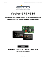
RS-485
Trasformatore di sicurezza
230 VAC / 24 VAC 4 VA
Non alimentare un altro
dispositivo con lo stesso
trasformatore
Rete elettrica
230 VAC
Modbus A (+)
Modbus B (-)
GND
SLAVE MODBUS
7
6
5
4
3
2
1
EPJcolor
Micro-switch
PRECAUTIONS FOR ELECTRICAL CONNECTION
-If using an electrical or pneumatic screwdriver,
adjust the tightening torque
-If the device has been moved from a cold to a warm
place, the humidity may have caused condensation to
form inside. Wait about an hour before switching on
the power
-Make sure that the supply voltage, electrical
frequency and power are within the set limits. See
the section TECHNICAL SPECIFICATIONS
-Disconnect the power supply before doing any type
of maintenance
-Do not use the device as safety device
Connector 2
Number Description
USB port, for programming the device.
Micro-switch
Number Description
1to terminate the RS485 Modbus network
001_EPJColor_Parete_AlimentazioneIndipendente_001_0.1_AZ
GND
+
-
+
-
+
-
7
6
5
4
3
2
1
EPJcolor
12
ON
12
ON
Device with
RS-485 port
RS-485 Micro-switch
230 VAC / 24 VAC 4 VA
safety transformer
Do not supply another
device with the same
transformer.
Electricity grid
230 VAC
Insertion of the RS-485 MODBUS port termination resistor
To insert the RS-485 MODBUS port termination resistor:
–Place micro-switch 2 in position ON
–Place micro-switch 2 in position OFF
The micro-switch is at the back of the device (remove the
back shell from the front before).
Electrical connection with independent power supply
Type Description
Purpose of the control device Function controller
Construction of the control
device Built-in electronic device
Container Black, self-extinguishing
Category of heat and re
resistance D
Dimensions 111,4 x 76,4 x 18,5 mm
Mounting methods for the
control device wall mounting
Degree of protection provided
by the covering IP30
Connection method Fixed screw terminal for wires up to 1
mm² blocks
Maximum permitted length
for connection cables
Power supply: 10 m
RS-485 MODBUS port: 1,000 m (3,280
ft)
Operating temperature -10 – 55 °C
Storage temperature -20 – 70 °C
Operating humidity Relative humidity without condensate
from 5 to 95%
Pollution status of the control
device 2
Compliance
- RoHS 2011/65/CE
- WEEE 2012/19/EU
- REACH (EC) Regulation N.
1907/2006
- RED 2014/53/UE
Power supply
24 VAC (±15%), 50/60 Hz (±3 Hz), max.
4 VA not insulated or 12... 30 VDC,
max. 2 W not insulated (independent
power supply or by a controller)
Earthing methods for the
control device none
Rated impulse-withstand
voltage I
Over-voltage category 330 V
Software class and structure A
Clock Incorporated secondary lithium
battery
Clock drift ≤ 55 s/month at 25 °C
Clock battery autonomy in the
absence of a power supply 6 month
Clock battery charging time 24 h (the battery is charged by the
power supply of the device)
Displays Colour touch-screen TFT graphic
display
Alarm buzzer Built-in
Communications ports - 1 RS-485 MODBUS port
- 1 USB port
3.TECHNICAL SPECIFICATIONS
EVCO S.p.A.
Via Feltre 81, 32036 Sedico (BL) ITALY - Tel. +39 0437 8422 - Fax +39 0437 83648 - e-mail info@evco.it - web www.evco.it
Questo documento e le soluzioni in esso contenute sono proprietà intellettuale EVCO tutelata dal Codice dei diritti di proprietà Industriale (CPI). EVCO pone
il divieto assoluto di riproduzione e divulgazione anche parziale dei contenuti se non espressamente autorizzata da EVCO stessa. Il cliente (costruttore,
installatore o utente nale) si assume ogni responsabilità in merito alla congurazione del dispositivo.
EVCO non si assume alcuna responsabilità in merito ai possibili errori riportati e si riserva il diritto di apportare qualsiasi modica in qualsiasi momento senza
pregiudicare le caratteristiche essenziali di funzionalità e di sicurezza.
004980 - 00 - 0920
X
X
VAC/+
VAC/-
CAN+/A+/B
CAN-/B-/GND
EPJcolor - Remote user interfaces
IMPORTANT
Read this document carefully before installation,
follow all the warnings before using the device.
Keep this document with the device for future
reference.
Use the device only in the manner described in this
document
USE
Device used for internal applications
DISPOSAL
The device must be disposed of according to local
regulations regarding the collection of electrical and
electronic equipment
EPJcolor is a programmable user interface with graphic
display, on-board regulation logic and MODBUS master /
slave communication.
Description
Features
24 VAC / DC - Color touch screen - Wall installation - RS485
- USB - Clock - Alarm buzzer
004_EPJColor_Parete_001_0.1_AZ
111,4 mm
18,5 mm
76,4 mm
2,75 in
1.DIMENSIONS
Wall
008_EPJColor_Parete_001_0.1_AZ
1. Unhook the back shell from the front through a
screwdriver and the proper seat.
2. Lean the back shell against the wall in a position
suitable to get the connecting cable to pass through the
proper opening.
3. Use the slots of the back shell as template to drill 4
holes having a diameter suitable to the bolt. 5.0 mm
(3/16 in) diameter bolts are suggested.
4. Insert the bolts in the holes drilled in the wall.
5. Fasten the back shell at the wall with 4 screws.
Countersunk head screws are suggested.
6. Make the electrical connection as shown in the section
ELECTRICAL CONNECTION without powering up the
device.
7. Fasten the front of the device at the back shell.
Seat
Front
Wall
Back shell
Slot
Opening to get the
connecting cables to pass
Conn.
cables
WARNINGS FOR INSTALLATION
-Ensure that the working conditions are within the limits
stated in the TECHNICAL SPECIFICATIONS section
-Do not install the device close to heat sources,
equipment with a strong magnetic eld, in places
subject to direct sunlight, rain, damp, excessive dust,
mechanical vibrations or shocks
- In compliance with safety regulations, the device must
be installed properly to ensure adequate protection
from contact with electrical parts. All protective parts
must be xed in such a way as to need the aid of a tool
to remove them.
WARNINGS FOR ELECTRICAL CONNECTIONS
-Use cables of an adequate section for the current
running through them
- To reduce any electromagnetic interference
connect the power cables as far away as possible
from the signal cables and connect to a CAN
network and RS-485 MODBUS network by using a
twisted pair.
7
6
5
4
3
2
1
002_EPJColor_Parete_DescrizConnettori_001_0.1_AZ
EPJcolor
12
ON
Connector 2
Connector 1
Micro-switch
2.ELECTRICAL CONNECTION
Connectors and parts
Connector 1
Number Description
3
device power supply (24 VAC/12... 30 VDC). If
the device is fed by DC power, connect terminal
minus
4device power supply (24 VAC/12... 30 VDC). If the
device is fed by DC power, connect terminal plus
5reference RS-485 MODBUS port (GND)
6RS-485 port reference - (MODBUS B)
7RS-485 port reference + (MODBUS A)
1 2
ON

EPJcolor - Remote user interfaces
IMPORTANT
Read this document carefully before installation,
follow all the warnings before using the device.
Keep this document with the device for future
reference.
Use the device only in the manner described in this
document
USE
Device used for internal applications
DISPOSAL
The device must be disposed of according to local
regulations regarding the collection of electrical and
electronic equipment
EPJcolor is a programmable user interface with graphic
display, on-board regulation logic and MODBUS master /
slave communication.
Description
Features
24 VAC / DC - Color touch screen - Wall installation - RS485
- USB - Clock - Alarm buzzer
111,4 mm
18,5 mm
76,4 mm
2,75 in
1.DIMENSIONS
Wall
1. Unhook the back shell from the front through a
screwdriver and the proper seat.
2. Lean the back shell against the wall in a position
suitable to get the connecting cable to pass through the
proper opening.
3. Use the slots of the back shell as template to drill 4
holes having a diameter suitable to the bolt. 5.0 mm
(3/16 in) diameter bolts are suggested.
4. Insert the bolts in the holes drilled in the wall.
5. Fasten the back shell at the wall with 4 screws.
Countersunk head screws are suggested.
6. Make the electrical connection as shown in the section
ELECTRICAL CONNECTION without powering up the
device.
7. Fasten the front of the device at the back shell.
Seat
Front
Wall
Back shell
Slot
Opening to get the
connecting cables to pass
Conn.
cables
WARNINGS FOR INSTALLATION
-Ensure that the working conditions are within the limits
stated in the TECHNICAL SPECIFICATIONS section
-Do not install the device close to heat sources,
equipment with a strong magnetic eld, in places
subject to direct sunlight, rain, damp, excessive dust,
mechanical vibrations or shocks
- In compliance with safety regulations, the device must
be installed properly to ensure adequate protection
from contact with electrical parts. All protective parts
must be xed in such a way as to need the aid of a tool
to remove them.
WARNINGS FOR ELECTRICAL CONNECTIONS
-Use cables of an adequate section for the current
running through them
- To reduce any electromagnetic interference
connect the power cables as far away as possible
from the signal cables and connect to a CAN
network and RS-485 MODBUS network by using a
twisted pair.
Connector 2
Connector 1
Micro-switch
2.ELECTRICAL CONNECTION
Connectors and parts
Connector 1
Number Description
3
device power supply (24 VAC/12... 30 VDC). If
the device is fed by DC power, connect terminal
minus
4device power supply (24 VAC/12... 30 VDC). If the
device is fed by DC power, connect terminal plus
5reference RS-485 MODBUS port (GND)
6RS-485 port reference - (MODBUS B)
7RS-485 port reference + (MODBUS A)
EPJcolor - Remote user interfaces
IMPORTANT
Read this document carefully before installation,
follow all the warnings before using the device.
Keep this document with the device for future
reference.
Use the device only in the manner described in this
document
USE
Device used for internal applications
DISPOSAL
The device must be disposed of according to local
regulations regarding the collection of electrical and
electronic equipment
EPJcolor is a programmable user interface with graphic
display, on-board regulation logic and MODBUS master /
slave communication.
Description
Features
24 VAC / DC - Color touch screen - Wall installation - RS485
- USB - Clock - Alarm buzzer
004_EPJColor_Parete_001_0.1_AZ
111,4 mm
18,5 mm
76,4 mm
2,75 in
1.DIMENSIONS
Wall
008_EPJColor_Parete_001_0.1_AZ
1. Unhook the back shell from the front through a
screwdriver and the proper seat.
2. Lean the back shell against the wall in a position
suitable to get the connecting cable to pass through the
proper opening.
3. Use the slots of the back shell as template to drill 4
holes having a diameter suitable to the bolt. 5.0 mm
(3/16 in) diameter bolts are suggested.
4. Insert the bolts in the holes drilled in the wall.
5. Fasten the back shell at the wall with 4 screws.
Countersunk head screws are suggested.
6. Make the electrical connection as shown in the section
ELECTRICAL CONNECTION without powering up the
device.
7. Fasten the front of the device at the back shell.
Seat
Front
Wall
Back shell
Slot
Opening to get the
connecting cables to pass
Conn.
cables
WARNINGS FOR INSTALLATION
-Ensure that the working conditions are within the limits
stated in the TECHNICAL SPECIFICATIONS section
-Do not install the device close to heat sources,
equipment with a strong magnetic eld, in places
subject to direct sunlight, rain, damp, excessive dust,
mechanical vibrations or shocks
- In compliance with safety regulations, the device must
be installed properly to ensure adequate protection
from contact with electrical parts. All protective parts
must be xed in such a way as to need the aid of a tool
to remove them.
WARNINGS FOR ELECTRICAL CONNECTIONS
-Use cables of an adequate section for the current
running through them
- To reduce any electromagnetic interference
connect the power cables as far away as possible
from the signal cables and connect to a CAN
network and RS-485 MODBUS network by using a
twisted pair.
7
6
5
4
3
2
1
002_EPJColor_Parete_DescrizConnettori_001_0.1_AZ
EPJcolor
12
ON
Connector 2
Connector 1
Micro-switch
2.ELECTRICAL CONNECTION
Connectors and parts
Connector 1
Number Description
3
device power supply (24 VAC/12... 30 VDC). If
the device is fed by DC power, connect terminal
minus
4device power supply (24 VAC/12... 30 VDC). If the
device is fed by DC power, connect terminal plus
5reference RS-485 MODBUS port (GND)
6RS-485 port reference - (MODBUS B)
7RS-485 port reference + (MODBUS A)

PRECAUTIONS FOR ELECTRICAL CONNECTION
-If using an electrical or pneumatic screwdriver,
adjust the tightening torque
-If the device has been moved from a cold to a warm
place, the humidity may have caused condensation to
form inside. Wait about an hour before switching on
the power
-Make sure that the supply voltage, electrical
frequency and power are within the set limits. See
the section TECHNICAL SPECIFICATIONS
-Disconnect the power supply before doing any type
of maintenance
-Do not use the device as safety device
Connector 2
Number Description
USB port, for programming the device.
Micro-switch
Number Description
1to terminate the RS485 Modbus network
Insertion of the RS-485 MODBUS port termination resistor
To insert the RS-485 MODBUS port termination resistor:
–Place micro-switch 2 in position ON
–Place micro-switch 1 in position OFF
The micro-switch is at the back of the device (remove the
back shell from the front before).
Electrical connection with independent power supply
Type Description
Purpose of the control device Function controller
Construction of the control
device Built-in electronic device
Container Black, self-extinguishing
Category of heat and re
resistance D
Dimensions 111,4 x 76,4 x 18,5 mm
Mounting methods for the
control device wall mounting
Degree of protection provided
by the covering IP30
Connection method Fixed screw terminal for wires up to 1
mm² blocks
Maximum permitted length
for connection cables
Power supply: 10 m
RS-485 MODBUS port: 1,000 m (3,280
ft)
Operating temperature -10 – 55 °C
Storage temperature -20 – 70 °C
Operating humidity Relative humidity without condensate
from 5 to 95%
Pollution status of the control
device 2
Compliance
- RoHS 2011/65/CE
- WEEE 2012/19/EU
- REACH (EC) Regulation N.
1907/2006
- RED 2014/53/UE
Power supply
24 VAC (±15%), 50/60 Hz (±3 Hz), max.
4 VA not insulated or 12... 30 VDC,
max. 2 W not insulated (independent
power supply or by a controller)
Earthing methods for the
control device none
Rated impulse-withstand
voltage I
Over-voltage category 330 V
Software class and structure A
Clock Incorporated secondary lithium
battery
Clock drift ≤ 55 s/month at 25 °C
Clock battery autonomy in the
absence of a power supply 6 month
Clock battery charging time 24 h (the battery is charged by the
power supply of the device)
Displays Colour touch-screen TFT graphic
display
Alarm buzzer Built-in
Communications ports - 1 RS-485 MODBUS port
- 1 USB port
3.TECHNICAL SPECIFICATIONS
EVCO S.p.A.
Via Feltre 81, 32036 Sedico (BL) ITALY - Tel. +39 0437 8422 - Fax +39 0437 83648 - e-mail info@evco.it - web www.evco.it
Questo documento e le soluzioni in esso contenute sono proprietà intellettuale EVCO tutelata dal Codice dei diritti di proprietà Industriale (CPI). EVCO pone
il divieto assoluto di riproduzione e divulgazione anche parziale dei contenuti se non espressamente autorizzata da EVCO stessa. Il cliente (costruttore,
installatore o utente nale) si assume ogni responsabilità in merito alla congurazione del dispositivo.
EVCO non si assume alcuna responsabilità in merito ai possibili errori riportati e si riserva il diritto di apportare qualsiasi modica in qualsiasi momento senza
pregiudicare le caratteristiche essenziali di funzionalità e di sicurezza.
004980 - 02 - 1222
PRECAUTIONS FOR ELECTRICAL CONNECTION
-If using an electrical or pneumatic screwdriver,
adjust the tightening torque
-If the device has been moved from a cold to a warm
place, the humidity may have caused condensation to
form inside. Wait about an hour before switching on
the power
-Make sure that the supply voltage, electrical
frequency and power are within the set limits. See
the section TECHNICAL SPECIFICATIONS
-Disconnect the power supply before doing any type
of maintenance
-Do not use the device as safety device
Connector 2
Number Description
USB port, for programming the device.
Micro-switch
Number Description
1to terminate the RS485 Modbus network
001_EPJColor_Parete_AlimentazioneIndipendente_001_0.1_AZ
GND
+
-
+
-
+
-
7
6
5
4
3
2
1
EPJcolor
12
ON
12
ON
Device with
RS-485 port
RS-485 Micro-switch
230 VAC / 24 VAC 4 VA
safety transformer
Do not supply another
device with the same
transformer.
Electricity grid
230 VAC
Insertion of the RS-485 MODBUS port termination resistor
To insert the RS-485 MODBUS port termination resistor:
–Place micro-switch 2 in position ON
–Place micro-switch 2 in position OFF
The micro-switch is at the back of the device (remove the
back shell from the front before).
Electrical connection with independent power supply
Type Description
Purpose of the control device Function controller
Construction of the control
device Built-in electronic device
Container Black, self-extinguishing
Category of heat and re
resistance D
Dimensions 111,4 x 76,4 x 18,5 mm
Mounting methods for the
control device wall mounting
Degree of protection provided
by the covering IP30
Connection method Fixed screw terminal for wires up to 1
mm² blocks
Maximum permitted length
for connection cables
Power supply: 10 m
RS-485 MODBUS port: 1,000 m (3,280
ft)
Operating temperature -10 – 55 °C
Storage temperature -20 – 70 °C
Operating humidity Relative humidity without condensate
from 5 to 95%
Pollution status of the control
device 2
Compliance
- RoHS 2011/65/CE
- WEEE 2012/19/EU
- REACH (EC) Regulation N.
1907/2006
- RED 2014/53/UE
Power supply
24 VAC (±15%), 50/60 Hz (±3 Hz), max.
4 VA not insulated or 12... 30 VDC,
max. 2 W not insulated (independent
power supply or by a controller)
Earthing methods for the
control device none
Rated impulse-withstand
voltage I
Over-voltage category 330 V
Software class and structure A
Clock Incorporated secondary lithium
battery
Clock drift ≤ 55 s/month at 25 °C
Clock battery autonomy in the
absence of a power supply 6 month
Clock battery charging time 24 h (the battery is charged by the
power supply of the device)
Displays Colour touch-screen TFT graphic
display
Alarm buzzer Built-in
Communications ports - 1 RS-485 MODBUS port
- 1 USB port
3.TECHNICAL SPECIFICATIONS
EVCO S.p.A.
Via Feltre 81, 32036 Sedico (BL) ITALY - Tel. +39 0437 8422 - Fax +39 0437 83648 - e-mail info@evco.it - web www.evco.it
Questo documento e le soluzioni in esso contenute sono proprietà intellettuale EVCO tutelata dal Codice dei diritti di proprietà Industriale (CPI). EVCO pone
il divieto assoluto di riproduzione e divulgazione anche parziale dei contenuti se non espressamente autorizzata da EVCO stessa. Il cliente (costruttore,
installatore o utente nale) si assume ogni responsabilità in merito alla congurazione del dispositivo.
EVCO non si assume alcuna responsabilità in merito ai possibili errori riportati e si riserva il diritto di apportare qualsiasi modica in qualsiasi momento senza
pregiudicare le caratteristiche essenziali di funzionalità e di sicurezza.
004980 - 00 - 0920
RS-485
230 VAC / 24 VAC 4 VA
safety transformer
Do not supply another
device with the same
transformer.
Electricity grid
230 VAC
Modbus A (+)
Modbus B (-)
GND
SLAVE MODBUS
7
6
5
4
3
2
1
EPJcolor
Micro-switch
PRECAUTIONS FOR ELECTRICAL CONNECTION
-If using an electrical or pneumatic screwdriver,
adjust the tightening torque
-If the device has been moved from a cold to a warm
place, the humidity may have caused condensation to
form inside. Wait about an hour before switching on
the power
-Make sure that the supply voltage, electrical
frequency and power are within the set limits. See
the section TECHNICAL SPECIFICATIONS
-Disconnect the power supply before doing any type
of maintenance
-Do not use the device as safety device
Connector 2
Number Description
USB port, for programming the device.
Micro-switch
Number Description
1to terminate the RS485 Modbus network
001_EPJColor_Parete_AlimentazioneIndipendente_001_0.1_AZ
GND
+
-
+
-
+
-
7
6
5
4
3
2
1
EPJcolor
12
ON
12
ON
Device with
RS-485 port
RS-485 Micro-switch
230 VAC / 24 VAC 4 VA
safety transformer
Do not supply another
device with the same
transformer.
Electricity grid
230 VAC
Insertion of the RS-485 MODBUS port termination resistor
To insert the RS-485 MODBUS port termination resistor:
–Place micro-switch 2 in position ON
–Place micro-switch 2 in position OFF
The micro-switch is at the back of the device (remove the
back shell from the front before).
Electrical connection with independent power supply
Type Description
Purpose of the control device Function controller
Construction of the control
device Built-in electronic device
Container Black, self-extinguishing
Category of heat and re
resistance D
Dimensions 111,4 x 76,4 x 18,5 mm
Mounting methods for the
control device wall mounting
Degree of protection provided
by the covering IP30
Connection method Fixed screw terminal for wires up to 1
mm² blocks
Maximum permitted length
for connection cables
Power supply: 10 m
RS-485 MODBUS port: 1,000 m (3,280
ft)
Operating temperature -10 – 55 °C
Storage temperature -20 – 70 °C
Operating humidity Relative humidity without condensate
from 5 to 95%
Pollution status of the control
device 2
Compliance
- RoHS 2011/65/CE
- WEEE 2012/19/EU
- REACH (EC) Regulation N.
1907/2006
- RED 2014/53/UE
Power supply
24 VAC (±15%), 50/60 Hz (±3 Hz), max.
4 VA not insulated or 12... 30 VDC,
max. 2 W not insulated (independent
power supply or by a controller)
Earthing methods for the
control device none
Rated impulse-withstand
voltage I
Over-voltage category 330 V
Software class and structure A
Clock Incorporated secondary lithium
battery
Clock drift ≤ 55 s/month at 25 °C
Clock battery autonomy in the
absence of a power supply 6 month
Clock battery charging time 24 h (the battery is charged by the
power supply of the device)
Displays Colour touch-screen TFT graphic
display
Alarm buzzer Built-in
Communications ports - 1 RS-485 MODBUS port
- 1 USB port
3.TECHNICAL SPECIFICATIONS
EVCO S.p.A.
Via Feltre 81, 32036 Sedico (BL) ITALY - Tel. +39 0437 8422 - Fax +39 0437 83648 - e-mail info@evco.it - web www.evco.it
Questo documento e le soluzioni in esso contenute sono proprietà intellettuale EVCO tutelata dal Codice dei diritti di proprietà Industriale (CPI). EVCO pone
il divieto assoluto di riproduzione e divulgazione anche parziale dei contenuti se non espressamente autorizzata da EVCO stessa. Il cliente (costruttore,
installatore o utente nale) si assume ogni responsabilità in merito alla congurazione del dispositivo.
EVCO non si assume alcuna responsabilità in merito ai possibili errori riportati e si riserva il diritto di apportare qualsiasi modica in qualsiasi momento senza
pregiudicare le caratteristiche essenziali di funzionalità e di sicurezza.
004980 - 00 - 0920
X
X
VAC/+
VAC/-
CAN+/A+/B
CAN-/B-/GND
1 2
ON
1/4