


SG Armaturen AS
SG Armaturen AS
Skytterheia 25
Skytterheia 25
4790 Lillesand
4790 Lillesand
NORGE
NORGE
Corporate offi ce:
Corporate offi ce:
www.sg-as.no
www.sg-as.no
Tlf:+47 37 50 03 00
Tlf:+47 37 50 03 00
SG Lighting SA/NV
73 rue de Saint Mandrier
83140 Six Fours Les Plages
FRANCE
Branch offi ce:
www.sglighting.net
Tlf:+33(0) 4 94 93 00 00
Branch offi ce:
Tlf:+45 70 70 72 13
www.sg-as.dk
SG Armaturen A/S
Egebakken 19
7400 Herning
DANMARK
SG Lighting SA/NV
Blokhuisstraat 47
2800 Mechelen Noord I
BELGIQUE/BELGIË
Branch offi ce:
Tlf:+32(0) 15 20 72 71
www. sglighting.net
SG Leuchten GmbH
Nordstrasse 53
59399 Olfen
GERMANY
Branch offi ce:
Tlf:+49 2595 3870 725
www.sg-leuchten.de
SG Armaturen AB
August Barksg. 30B
421 32 Västra Frölunda
SVERIGE
Branch offi ce:
Tlf:+46 31 81 71 10
www.sg-ab.se
Rev: 11.10.2017
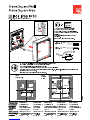
N
L
L
N
N’
L
N
L
N
Sensor Slave Slave
L
NN
Sensor
L’
L
N’
L’
L
N
N’
L
N
L
N
Sensor Slave Slave
L
N
Sensor
L’
N
L
N’
L’
PE
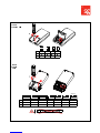
40-60% 60-80%
Fe
0-10% 0% 80-90%
40-60% 60-80%
80-90% 0-10% 0%
100%
75%
50%
25%
10%
1 2 3
4
4
10
30
Standby power < 0.5W
Microwave frequency 5.8GHz+/-75MHz
Microwave power < 0.2mW
Max 400W
Sensor + Basic light:
Sensor:
I
I
I
I
I
I
I
I
I
I
I
I
I
I
I
I
I
I
I
I
I
I
I
I
I
I
I
I
I
I
I
I
100%
100%
0%
2W
HC009S sensor
230V, 50Hz

SG Armaturen AS
Tlf:+47 37 50 03 00
www.sg-as.no
SG Lighting SA/NV
Tel: +33(0) 4 94 93 00 00
www.sglighting.net
SG Armaturen A/S
Tel: +45 70 70 72 13
www.sg-as.dk
SG Lighting SA/NV
Tel: +32(0) 15 20 72 71
www.sglighting.net
SG Armaturen AB
Tel: +46 31 81 71 10
www.sg-ab.se
SG Leuchten GmbH
Tel: +49 40 23 99 44 59
www.sg-leuchten.de
SG Armaturen Oy
info@sg-oy.
www.sg-oy.
SG Lighting Co Ltd.
Tel: +86 769 88 49 20 88
www.sg-as.com
NORWAY FRANCE GERMANYSWEDEN
DENMARK BENELUX INTERNATIONALFINLAND
Rev: 12.01.2018
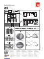
1 2
ON
1 2
ON
1 2
ON
1 2
ON
180 mA
205 mA
230 mA
255 mA
1 2
ON
1 2
ON
1 2
ON
1 2
ON
180 mA
205 mA
230 mA
255 mA
1 2
ON
1 2
ON
1 2
ON
1 2
ON
180 mA
205 mA
230 mA
255 mA
1 2
ON
1 2
ON
1 2
ON
1 2
ON
180 mA
205 mA
230 mA
255 mA
SWITCH SENSOR
S1 S2 Sensor LUX Level Open (LUX) Close (LUX)
ON ON 100 150
ON OFF 80 130
OFF ON 70 120
OFF OFF 50 100
< 0,5 W
Max. 200 W
Standard
IR
IR LED
Twilight sensor
230V, 50/60Hz
60 sec

Inst 071-2 LDM 01-18
.
PLEASE READ THESE INSTRUCTIONS CAREFULLY AND KEEP FOR FUTURE REFERENCE.
INSTALLATION AND OPERATION INSTRUCTIONS FOR
LDM RANGE
EMERGENCY LIGHTING PRODUCTS
INTRODUCTION
The LDM range comprises a high quality emergency LED control module complying to international safety and performance
standards IEC 61347-1, IEC 61347-2-7, IEC 61347-2-13, IEC 62384 and IEC 60598-2-22, and an appropriate high temperature
NiCad or LiFePO4 battery pack. The DALI/Self-test modules also comply with IEC62386-202 and IEC 62034.
It is essential that Emergency Lighting equipment is installed and operated correctly to ensure compliance with the relevant
directives and to optimise long-term performance.
Install equipment in accordance with the relevant national requirements including ICEL 1004 and ensure that each complete
luminaire complies with the Electro Magnetic Compatibility Directive and the Low Voltage Directive. Compliance is indicated by
application of the CE Mark. Installation of equipment must be carried out by competent persons and suitable tests on the
completed luminaire must be carried out to ensure compliance to relevant standards.
GENERAL GUIDELINES
The important factors relating to compliance are summarised below:
• The LDM emergency LED control module and associated battery pack must be suitably positioned to avoid high temperatures.
Note: the ambient temperature range for the module and battery pack is 0 - 50°C, and the value of tc for the module is 60°C. In
some cases where the luminaire is physically too small to house the emergency lighting equipment or if the ambient temperature
within the luminaire is too high, a fully remote unit will be required.
• The modules are supplied with push wire terminal blocks suitable for 0.5 –1.5mm2 cables, except for the indicator LED
terminals which are suitable for 0.4 –0.8mm2 cables. All cables between the control module and the LED luminaire must be
as short as possible and be of an approved heat resisting type.
• The battery charger healthy indicator LED (for the DALI/Self-test module the indicator LED is a bi-colour local status LED)
should be positioned so that it is clearly visible when the luminaire is installed.
• Mains supply cables and LED circuit cables should be physically segregated.
Note:
a) The LDM range is protected against battery reversal by means of a resettable PCB mounted fuse.
b) The battery charger healthy indicator LED for the standard LDM will flash triple pulses if the load terminals are open circuit.
OPERATION AND TESTING
• The LED luminaire should be installed in accordance with Original Equipment Manufacturers instructions.
• Wiring complying with the relevant wiring regulations should include a permanent 230/240 volt 50Hz supply for battery charging
and monitoring purposes.
• Luminaires incorporating LDM equipment should be connected to the normal mains supplies for a minimum of 24 hours
before operating in emergency lighting mode as the batteries require a 24 hour charge before they will provide full rated
duration. (NOTE DALI/Self-test modules have a self-commissioning mode which charges the battery, does a full duration
test and then re-charges the battery).
All emergency lighting installations should be regularly tested, and the results recorded. The appropriate test schedule is detailed
in BS 5266. The test schedule should cover the recommended minimum assessments (given below) but should not include an
excessive number of tests if battery life is to be optimised:
Monthly - luminaires should be put into emergency lighting operation for a period not exceeding one quarter of the rated duration.
Each luminaire should be inspected for satisfactory LED starting and stable operation. When the normal mains supply is re-
instated, the battery charge healthy indicator should be on.
Annually -the monthly test should be carried out, but the luminaire should also be operated for its full rated duration.
Note:
a) Tests should be carried out at times where the building will not be re-occupied until the batteries have fully re-charged.
b) Failure to achieve rated duration indicates that the batteries have reached the end of their useful life and they should be
replaced immediately.
SAFETY INFORMATION
The LDM emergency LED control modules do not rely upon a luminaire enclosure to provide protection against accidental contact
with live parts.
The LDM emergency LED control modules feature double/reinforced insulation and the outputs to the LED luminaire (for outputs
<100V), battery and local indicator LED are SELV outputs.
The electronics and batteries will be damaged by excessive temperatures and it is therefore important that they are always
operated within the declared ‘ta’ ambient temperature range.
Batteries have a typical life expectancy of four to five years. Old batteries should be handled by specialist waste disposal experts,
and under no circumstances should they be pierced or incinerated.
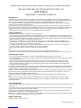
WIRING CONNECTIONS
For typical wiring connections see over.

Inst 071-2 LDM 01-18
DALI COMMUNICATION (DALI/ST MODULES ONLY)
DALI modules will respond to DALI commands from a suitable control unit, and these commands can be used to initiate function
and duration tests at prescribed times. The status flags for the module are set after a test, for reporting and logging of the results.
DALI /Self-test module local LED indicator
Green LED
Permanently on
System OK/mains operation mode
Slow flash
Duration test/commissioning
Fast flash
Function test
Red LED
Permanently on
LED luminaire fault
Slow flash
Battery/test failure
Fast flash
Battery charging failure
Slow flash – a flash every 2 seconds, Fast flash – a flash every 0.5 second
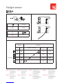
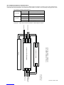
TYPICAL WIRING DIAGRAM FOR
LDM RANGE OF CONTROL GEAR
Ind.LED+
Ind.Led-
Batt+
Batt-
Load+
Load-
Input+
Input-
LDM Emergency Control Gear
Lout
Lin
L
N
Da
Da
Load+
Load-
Mains Control Gear
L
N
Battery
Switched Live
Unswitched Live
Neutral
DALI Input*
* DALI Emergency
Control Gear only
To LED Luminiare
Indicator LED
-
 1
1
-
 2
2
-
 3
3
-
 4
4
-
 5
5
-
 6
6


