Yamaha DME4io Manuale del proprietario
- Categoria
- Mixer audio
- Tipo
- Manuale del proprietario

EN
DIGITAL MIXING ENGINE SATELLITE
Owner’s Manual

The above warning is located on the top of the unit.
Explanation of Graphical Symbols
The lightning flash with arrowhead symbol
within an equilateral triangle is intended to alert
the user to the presence of uninsulated
“dangerous voltage” within the product’s
enclosure that may be of sufficient magnitude to
constitute a risk of electric shock to persons.
The exclamation point within an equilateral
triangle is intended to alert the user to the
presence of important operating and
maintenance (servicing) instructions in the
literature accompanying the product.
IMPORTANT SAFETY INSTRUCTIONS
1 Read these instructions.
2Keep these instructions.
3 Heed all warnings.
4 Follow all instructions.
5 Do not use this apparatus near water.
6 Clean only with dry cloth.
7 Do not block any ventilation openings. Install in
accordance with the manufacturer’s instructions.
8 Do not install near any heat sources such as radiators,
heat registers, stoves, or other apparatus (including
amplifiers) that produce heat.
9 Do not defeat the safety purpose of the polarized or
grounding-type plug. A polarized plug has two blades
with one wider than the other. A grounding type plug
has two blades and a third grounding prong. The wide
blade or the third prong are provided for your safety. If
the provided plug does not fit into your outlet, consult
an electrician for replacement of the obsolete outlet.
10 Protect the power cord from being walked on or pinched
particularly at plugs, convenience receptacles, and the
point where they exit from the apparatus.
11 Only use attachments/accessories specified by the
manufacturer.
12 Use only with the cart, stand,
tripod, bracket, or table specified
by the manufacturer, or sold with
the apparatus. When a cart is
used, use caution when moving
the cart/apparatus combination
to avoid injury from tip-over.
13 Unplug this apparatus during
lightning storms or when unused for long periods of
time.
14 Refer all servicing to qualified service personnel.
Servicing is required when the apparatus has been
damaged in any way, such as power-supply cord or plug
is damaged, liquid has been spilled or objects have
fallen into the apparatus, the apparatus has been
exposed to rain or moisture, does not operate normally,
or has been dropped.
(98-6500)
CAUTION: TO REDUCE THE RISK OF
ELECTRIC SHOCK, DO NOT REMOVE
COVER (OR BACK). NO USER-SERVICEABLE
PARTS INSIDE. REFER SERVICING TO
QUALIFIED SERVICE PERSONNEL.
CAUTION
RISK OF ELECTRIC SHOCK
DO NOT OPEN
WARNING
TO REDUCE THE RISK OF FIRE OR ELECTRIC SHOCK, DO NOT EXPOSE THIS APPARATUS TO RAIN OR MOISTURE.
* This applies only to products distributed by YAMAHA CORPORATION OF AMERICA. (Perchlorate)
This product contains a battery that contains perchlorate material.
Perchlorate Material—special handling may apply,
See www.dtsc.ca.gov/hazardouswaste/perchlorate.

1. IMPORTANT NOTICE: DO NOT MODIFY THIS UNIT!
This product, when installed as indicated in the instructions con-
tained in this manual, meets FCC requirements. Modifications not
expressly approved by Yamaha may void your authority, granted by
the FCC, to use the product.
2. IMPORTANT:
When connecting this product to accessories and/
or another product use only high quality shielded cables. Cable/s
supplied with this product MUST be used. Follow all installation
instructions. Failure to follow instructions could void your FCC
authorization to use this product in the USA.
3. NOTE:
This product has been tested and found to comply with the
requirements listed in FCC Regulations, Part 15 for Class “B” digital
devices. Compliance with these requirements provides a reason-
able level of assurance that your use of this product in a residential
environment will not result in harmful interference with other elec-
tronic devices. This equipment generates/uses radio frequencies
and, if not installed and used according to the instructions found in
the users manual, may cause interference harmful to the operation
of other electronic devices. Compliance with FCC regulations does
* This applies only to products distributed by YAMAHA CORPORATION OF AMERICA. (class B)
not guarantee that interference will not occur in all installations. If
this product is found to be the source of interference, which can be
determined by turning the unit “OFF” and “ON”, please try to elimi-
nate the problem by using one of the following measures:
Relocate either this product or the device that is being affected by
the interference.
Utilize power outlets that are on different branch (circuit breaker or
fuse) circuits or install AC line filter/s.
In the case of radio or TV interference, relocate/reorient the
antenna. If the antenna lead-in is 300 ohm ribbon lead, change the
lead-in to co-axial type cable.
If these corrective measures do not produce satisfactory results,
please contact the local retailer authorized to distribute this type of
product. If you can not locate the appropriate retailer, please con-
tact Yamaha Corporation of America, Electronic Service Division,
6600 Orangethorpe Ave, Buena Park, CA90620
The above statements apply ONLY to those products distributed by
Yamaha Corporation of America or its subsidiaries.
FCC INFORMATION (U.S.A.)
ADVARSEL!
Lithiumbatteri—Eksplosionsfare ved fejlagtig håndtering. Udskift-
ning må kun ske med batteri af samme fabrikat og type. Levér det
brugte batteri tilbage til leverandoren.
VARNING
Explosionsfara vid felaktigt batteribyte. Använd samma batterityp
eller en ekvivalent typ som rekommenderas av apparattillverkaren.
Kassera använt batteri enligt fabrikantens instruktion.
VAROITUS
Paristo voi räjähtää, jos se on virheellisesti asennettu. Vaihda
paristo ainoastaan laitevalmistajan suosittelemaan tyyppiin. Hävitä
käytetty paristo valmistajan ohjeiden mukaisesti.
(lithium caution)
IMPORTANT NOTICE FOR THE UNITED KINGDOM
Connecting the Plug and Cord
WARNING:
THIS APPARATUS MUST BE EARTHED
IMPORTANT. The wires in this mains lead are coloured in accor-
dance with the following code:
GREEN-AND-YELLOW : EARTH
BLUE : NEUTRAL
BROWN : LIVE
As the colours of the wires in the mains lead of this apparatus may
not correspond with the coloured markings identifying the terminals
in your plug proceed as follows:
The wire which is coloured GREEN-and-YELLOW must be con-
nected to the terminal in the plug which is marked by the letter E or
by the safety earth symbol or colored GREEN or GREEN-and-
YELLOW.
The wire which is coloured BLUE must be connected to the termi-
nal which is marked with the letter N or coloured BLACK.
The wire which is coloured BROWN must be connected to the ter-
minal which is marked with the letter L or coloured RED.
• This applies only to products distributed by Yamaha-Kemble Music (U.K.) Ltd.(3 wires)
* This applies only to products distributed by
YAMAHA CORPORATION OF AMERICA.
COMPLIANCE INFORMATION STATEMENT
(DECLARATION OF CONFORMITY PROCEDURE)
Responsible Party : Yamaha Corporation of America
Address : 6600 Orangethorpe Ave., Buena Park, Calif.
90620
Telephone : 714-522-9011
Type of Equipment : DIGITAL MIXING ENGINE SATELLITE
Model Name : DME8i-C/DME8o-C/DME4io-C
This device complies with Part 15 of the FCC Rules.
Operation is subject to the following two conditions:
1) this device may not cause harmful interference, and
2) this device must accept any interference received including inter-
ference that may cause undesired operation.
See user manual instructions if interference to radio reception is sus-
pected.
(FCC DoC)
NEDERLAND / THE NETHERLANDS
• Dit apparaat bevat een lithium batterij voor geheugen back-up.
• This apparatus contains a lithium battery for memory back-up.
• Raadpleeg uw leverancier over de verwijdering van de batterij op
het moment dat u het apparaat ann het einde van de levensduur of
gelieve dan contact op te nemen met de vertegenwoordiging van
Yamaha in uw land.
•For the removal of the battery at the moment of the disposal at the
end of life please consult your retailer or Yamaha representative
office in your country.
• Gooi de batterij niet weg, maar lever hem in als KCA.
• Do not throw away the battery. Instead, hand it in as small chemical
waste.
(lithium disposal)

DME8i-C/DME8o-C/DME4io-C Owner’s Manual
4
PRECAUTIONS
PLEASE READ CAREFULLY BEFORE PROCEEDING
* Please keep this manual in a safe place for future reference.
WARNING
Always follow the basic precautions listed below to avoid the possibility of serious injury or even death from electrical
shock, short-circuiting, damages, fire or other hazards. These precautions include, but are not limited to, the following:
• Only use the voltage specified as correct for the device. The required voltage is
printed on the name plate of the device.
• Use only the included power cord. If you intend to use the device in an area
other than in the one you purchased, the included power cord may not be
compatible. Please check with your Yamaha dealer.
• Do not place the power cord near heat sources such as heaters or radiators, and
do not excessively bend or otherwise damage the cord, place heavy objects on
it, or place it in a position where anyone could walk on, trip over, or roll anything
over it.
• Be sure to connect to an appropriate outlet with a protective grounding
connection. Improper grounding can result in electrical shock.
• Do not open the device or attempt to disassemble the internal parts or modify
them in any way. The device contains no user-serviceable parts. If it should
appear to be malfunctioning, discontinue use immediately and have it inspected
by qualified Yamaha service personnel.
• Do not expose the device to rain, use it near water or in damp or wet conditions,
or place containers on it containing liquids which might spill into any openings.
• Never insert or remove an electric plug with wet hands.
• If the power cord or plug becomes frayed or damaged, or if there is a sudden
loss of sound during use of the device, or if any unusual smells or smoke
should appear to be caused by it, immediately turn off the power switch,
disconnect the electric plug from the outlet, and have the device inspected by
qualified Yamaha service personnel.
• If this device should be dropped or damaged, immediately turn off the power
switch, disconnect the electric plug from the outlet, and have the device
inspected by qualified Yamaha service personnel.
CAUTION
Always follow the basic precautions listed below to avoid the possibility of physical injury to you or others, or damage
to the device or other property. These precautions include, but are not limited to, the following:
• Remove the electric plug from the outlet when the device is not to be used for
extended periods of time, or during electrical storms.
• When removing the electric plug from the device or an outlet, always hold the
plug itself and not the cord. Pulling by the cord can damage it.
• Before moving the device, remove all connected cables.
• When setting up the product, make sure that the AC outlet you are using is
easily accessible. If some trouble or malfunction occurs, immediately turn off
the power switch and disconnect the plug from the outlet. Even when the power
switch is turned off, electricity is still flowing to the product at the minimum
level. When you are not using the product for a long time, make sure to unplug
the power cord from the wall AC outlet.
• If this device is to be mounted in an EIA-standard rack, leave the back of the rack
open and make sure that it is at least 10 cm away from walls or surfaces. Also, if
this device is to be mounted with devices that tend to generate heat, such as
power amplifiers, be sure to keep an adequate gap between this device and the
heat-generating devices or install ventilation panels to prevent high
temperatures from developing inside this device.
Inadequate ventilation can result in overheating, possibly causing damage to the
device(s), or even fire.
• If several of the devices are mounted in an EIA-compliant rack, carefully read the
section “Precautions for Using a Rack-mounted DME Satellite” on page 8.
•Avoid setting all equalizer controls and faders to their maximum. Depending on
the condition of the connected devices, doing so may cause feedback and may
damage the speakers.
• Do not expose the device to excessive dust or vibrations, or extreme cold or heat
(such as in direct sunlight, near a heater, or in a car during the day) to prevent
the possibility of panel disfiguration or damage to the internal components.
• Do not place the device in an unstable position where it might accidentally fall
over.
• Do not block the vents. This device has ventilation holes at the rear to prevent
the internal temperature from becoming too high. In particular, do not place the
device on its side or upside down. Inadequate ventilation can result in
overheating, possibly causing damage to the device(s), or even fire.
• Do not use the device in the vicinity of a TV, radio, stereo equipment, mobile
phone, or other electric devices. Doing so may result in noise, both in the device
itself and in the TV or radio next to it.
Power supply/Power cord
Do not open
Water warning
If you notice any abnormality
Power supply/Power cord
Location
(5)-4
1/2

DME8i-C/DME8o-C/DME4io-C Owner’s Manual
5
• Before connecting the device to other devices, turn off the power for all devices.
Before turning the power on or off for all devices, set all volume levels to
minimum.
• Do not insert your fingers or hands in any gaps or openings on the device.
• Condensation can occur in the device due to rapid, drastic changes in ambient
temperature—when the device is moved from one location to another, or air
conditioning is turned on or off, for example. Using the device while
condensation is present can cause damage. If there is reason to believe that
condensation might have occurred, leave the device for several hours without
turning on the power until the condensation has completely dried out.
•Avoid inserting or dropping foreign objects (paper, plastic, metal, etc.) into any
gaps or openings on the device. If this happens, turn off the power immediately
and unplug the power cord from the AC outlet. Then have the device inspected
by qualified Yamaha service personnel.
• Do not use the device for a long period of time at a high or uncomfortable
volume level, since this can cause permanent hearing loss. If you experience
any hearing loss or ringing in the ears, consult a physician.
• Do not rest your weight on the device or place heavy objects on it, and avoid use
excessive force on the buttons, switches or connectors.
• This device has a built-in backup battery that maintains data in internal memory
even when the device’s power is switched off. The backup battery will eventually
become depleted, however, and when that happens the contents of the internal
memory will be lost.* To prevent loss of data be sure to replace the backup
battery before it becomes fully depleted. When the backup battery charge
becomes low, the [ERROR] indicator on the front panel blinks (For details, refer
to “Error Messages” on page 42).
In this case, do not turn off the power and immediately transfer any data you
want to save to a computer or other external storage device, then have qualified
Yamaha service personnel replace the backup battery. The average life of the
internal backup battery is approximately 5 years, depending on operating
conditions.
* Data items maintained in the internal memory by the backup battery are as
follows:
• Current scene parameters and number.
• Device parameters (CobraNet, HA, UTILITY, Master Mute/Level, etc.).
• Event log.
Data items other than those described above are stored in memory that does not
require backup power, and will be retained even if the backup battery fails.
Do not turn the [POWER] switch on and off repeatedly and rapidly. Be sure to wait six seconds or more between turning the power to the unit off and then on.
The rubber feet included in this package can be attached to the bottom of this device to prevent slippage when it is to be used on a slippery surface.
Always turn the power off when the device is not in use.
The performance of components with moving contacts, such as switches, volume controls, and connectors, deteriorates over time. Consult qualified Yamaha service
personnel about replacing defective components.
Connections
Handling caution
Backup battery
Yamaha cannot be held responsible for damage caused by improper use or modifications to the device, or data that is lost or destroyed.
• The illustrations in this owner’s manual are for instructional purposes, and may appear somewhat different from the actual equipment.
• CobraNet is a trademark of Cirrus Logic, Inc.
• Ethernet is a trademark of Xerox Corporation.
• All other trademarks are the property of their respective holders and are hereby acknowledged.
(5)-4
2/2

DME8i-C/DME8o-C/DME4io-C Owner’s Manual
Foreword
Introduction to
the DME Satellite
Controls and
Connectors
Connecting to
a Computer
Audio I/O
Connection
Connecting to an
External Device
Other Functions
References
6
Foreword .......................................... 7
Accessories (Please make sure the following items are
included in the package.) ..................................... 7
Options........................................................................... 7
About the Product Names............................................... 7
About the Firmware Version ........................................... 7
Preparation...................................................................... 7
Connecting the AC power cord........................................... 7
Turning the power on and off ............................................. 7
Precautions for Using a Rack-mounted DME Satellite.... 8
Introduction to the DME Satellite .............. 9
Differences between DME8i-C, DME8o-C,
and DME4io-C ................................................... 9
DME Satellite Features ................................................... 9
Audio System Network ................................................. 10
Glossary for the DME Satellite...................................... 10
Signal Types.................................................................. 12
System Examples........................................................... 13
About DME Designer................................................... 14
About CobraNet ........................................................... 15
CobraNet in a nutshell...................................................... 15
Bundle .............................................................................. 15
Multicast and unicast bundles ........................................... 16
Conductors and performers............................................... 17
Cables and hubs for CobraNet network ............................ 17
Controls and Connectors ....................... 18
Front Panel ................................................................... 18
Caution when turning the power off ............................. 19
Rear Panel..................................................................... 20
Connecting to a Computer ..................... 22
USB Connection........................................................... 22
Network Settings........................................................... 23
Setting the IP address........................................................ 23
Master and slave setting..................................................... 23
Ethernet Connection ([NETWORK] Connector)......... 24
Audio I/O Connection ........................... 28
Digital Audio Connection (CobraNet Connectors)....... 28
Analog Audio Connection ([INPUT] & [OUTPUT]
Connectors) ....................................................... 29
Connecting to an External Device............. 30
Remote Connection ([REMOTE] Connector).............. 30
Controlling external head amplifiers from the DME
Satellite ................................................................. 30
Controlling a DME Satellite’s internal head amps from a
digital mixer .......................................................... 31
Controlling the DME Satellite from an external device...... 31
CobraNet Connection (CobraNet Connectors)............. 32
Controlling DME Satellite’s internal head amps from a
digital mixer Yamaha LS9...................................... 32
Controlling the DME Satellite from a digital mixer
Yamaha PM5D ..................................................... 33
Network Connection ([NETWORK] Connectors ........ 33
GPI Connection ([GPI] Connector).............................. 34
Other Functions.................................. 35
Initializing the DME Satellite........................................ 35
References ....................................... 36
Options ......................................................................... 36
ICP1.................................................................................. 36
CP4SW, CP4SF, and CP1SF............................................. 36
Troubleshooting............................................................ 37
Component................................................................... 37
MIDI Data Format ....................................................... 38
1. MIDI functions on the DME8i-C, DME8o-C, and
DME4io-C ........................................................... 38
2. MIDI Data Flow ........................................................... 38
3. MIDI Setup................................................................... 38
4. MIDI Format ................................................................ 39
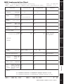
MIDI Implementation Chart ........................................ 41
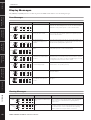
Display Messages........................................................... 42
Error Messages................................................................... 42
Warning Messages ............................................................. 42
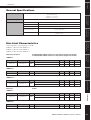
General Specifications ................................................... 43
Electrical Characteristics................................................ 43
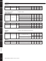
Input/Output Characteristics ........................................ 46
[NETWORK] Connector (100Base-TX Ethernet,
RJ-45)................................................................ 47
Straight and Crossover Cable Wiring............................. 47
Dimensions ................................................................... 48
Index ............................................................................. 49
Contents

References
Other Functions
Connecting to an
External Device
Audio I/O
Connection
Connecting to
a Computer
Controls and
Connectors
Introduction to
the DME Satellite
Foreword
DME8i-C/DME8o-C/DME4io-C Owner’s Manual
7
Thank you for choosing a Yamaha DME8i-C/DME8o-C/DME4io-C Digital Mixing Engine Satellite.
In order to take full advantage of the features and performance provided by the DME8i-C/DME8o-C/DME4io-C, we urge you
to read this owner’s manual thoroughly before connecting or using the unit. Keep this manual in a safe place for future reference.
Accessories (Please make
sure the following items are
included in the package.)
• DME8i-C/DME8o-C/DME4io-C Owner’s Manual
(this document)
•AC power cord
•Euroblock plug (16P) x 1
•Euroblock plug (3P) x 8
•Rubber feet x 4
Options
Control Panels
• ICP1 Intelligent Control Panel
• CP4SW Control Panel
• CP4SF Control Panel
• CP1SF Control Panel
About the Product Names
In this manual, models DME8i-C, DME8o-C, and
DME4io-C are all called “DME Satellite,” and models
DME64N and DME24N, DME8i-ES/DME8o-ES/
DME4io-ES and the DME Satellite are categorized as the
DME series.
About the Firmware Version
You can check the version number of the DME Satellite
firmware by using the DME Designer application software.
You can also download the latest firmware from the follow-
ing Yamaha website.
http://www.yamahaproaudio.com/downloads/
Preparation
Connecting the AC power cord
First plug the female-connector end of the AC cord into the
[AC IN] socket on the rear panel of the DME Satellite, then
plug the male plug into an appropriate AC mains outlet.
Be sure to use the voltage specified for the device.
Turning the power on and off
1.
Press the [POWER] switch to turn on the
power to the DME Satellite.
2.
Press the [POWER] switch again to turn off
the power.
Foreword
NOTE
For more information on your Control Panel, refer to the owner’s
manual that came with the Control Panel, as well as the DME
Designer Owner’s Manual.
Be sure to turn all devices OFF before connecting AC
mains power.
To prevent the initial power-on surge from generating a
large noise spike or damaging your speaker system, turn
the devices on in the following order: audio sources, mixer
(such as M7CL or PM5D), DME Satellite, and finally
power amplifiers.
Reverse this order when turning power off.
NOTE
The DME Satellite remembers scene settings when you turn off
the power.
When you turn on the power to the DME Satellite, it will start up
with the same scene settings.
You can use the “Last Mem. Resume” setting in DME Designer
to set up the DME Satellite so that at the startup it will recall the
scene selected before you turned off the power to the device.
•Do NOT turn off the power to the DME Satellite while
it is receiving data from DME Designer or while it is
being manipulated from an external device. Otherwise,
a malfunction may occur.
•Even when the power switch is turned off, electricity is
still flowing to the product all the minimum level.
When you are not using the product for a long time,
make sure to unplug the power cord from the wall AC
outlet.
CAUTION
CAUTION
CAUTION

Foreword
DME8i-C/DME8o-C/DME4io-C Owner’s Manual
Foreword
Introduction to
the DME Satellite
Controls and
Connectors
Connecting to
a Computer
Audio I/O
Connection
Connecting to an
External Device
Other Functions
References
8
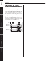
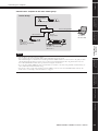
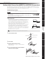
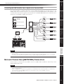
Precautions for Using a
Rack-mounted DME Satellite
If several DME Satellite units (or a DME Satellite unit to-
gether with other devices) are installed in a poorly-ventilated
rack, the heat generated by each unit may raise the tempera-
ture inside the rack, preventing the DME Satellite from per-
forming as designed. When mounting DME Satellite units
in a rack, please leave one rack space vacant for every two
units. You can attach a ventilation panel to this space or leave
it open to prevent excessive heat build-up.
If the temperature inside the rack is expected to rise above 40
degrees Celsius or 104 degrees Fahrenheit (or if the ambient
temperature outside the rack is expected to rise above 30 de-
grees Celsius or 86 Fahrenheit), install a fan kit in the top
row of the rack. The fan must provide airflow of 1.6m
3
/min
or more and static pressure of 5mmH
2
O or more.
Fan kit
DME Satellite
DME Satellite
USB
PEAK
PEAK
SIGNAL
SIGNAL
PEAK
PEAK
SIGNAL
SIGNAL
PEAK
PEAK
SIGNAL
SIGNAL
INPUT
INPUT
DIGITAL MIXING ENGINE SATELLITE
USB
PEAK
PEAK
SIGNAL
SIGNAL
PEAK
PEAK
SIGNAL
SIGNAL
PEAK
PEAK
SIGNAL
SIGNAL
INPUT
INPUT
DIGITAL MIXING ENGINE SATELLITE
USB
PEAK
PEAK
SIGNAL
SIGNAL
PEAK
PEAK
SIGNAL
SIGNAL
PEAK
PEAK
SIGNAL
SIGNAL
INPUT
INPUT
DIGITAL MIXING ENGINE SATELLITE
USB
PEAK
PEAK
SIGNAL
SIGNAL
PEAK
PEAK
SIGNAL
SIGNAL
PEAK
PEAK
SIGNAL
SIGNAL
INPUT
INPUT
DIGITAL MIXING ENGINE SATELLITE
DME Satellite
DME Satellite
Ventilation panel

References
Other Functions
Connecting to an
External Device
Audio I/O
Connection
Connecting to
a Computer
Controls and
Connectors
Introduction to
the DME Satellite
Foreword
DME8i-C/DME8o-C/DME4io-C Owner’s Manual
9
Differences between DME8i-C, DME8o-C, and DME4io-C
The differences between these three models are as follows:
■
DME8i-C
This model features 8-channel analog inputs.
■
DME8o-C
This model features 8-channel analog outputs.
■
DME4io-C
This model features 4-channel analog inputs and 4-channel analog outputs.
DME Satellite Features
In addition to basic mixing and matrix output functions, the DME Satellite includes a equalizers, compressors,
delay, etc. – that can be patched together via DME Designer to configure just about any audio system you need.
The CobraNet connectors on the device enable you to remotely control analog inputs and outputs by transferring
digital audio signals via a network.
The following steps summarize the process for setting up the DME Satellite for use:
(For details, refer to the “DME Setup Manual”.)
1.
Install USB-MIDI Driver, DME Designer and DME-N Network Driver.
2.
Set up the network from DME Designer (page 23).
3.
Connect devices.
• Network connection
Ethernet connection (page 24)
USB connection (page 22)
• CobraNet connection (page 32)
• Analog connection (page 29)
• External device connection
Remote connection (page 30)
GPI connection (page 34)
4.
Make network settings on your computer.
5.
Create a configuration using DME Designer, then transfer it to the DME Satellite.
(Refer to the DME Designer Owner’s Manual for details.)
Introduction to the DME Satellite

Introduction to the DME Satellite
DME8i-C/DME8o-C/DME4io-C Owner’s Manual
Foreword
Introduction to
the DME Satellite
Controls and
Connectors
Connecting to
a Computer
Audio I/O
Connection
Connecting to an
External Device
Other Functions
References
10
Audio System Network
Multiple DME series units that are interconnected in a network via Ethernet function as a single audio system.
In a DME audio system, a group of the same models that can be operated in sync is called a “device group;” audio
processing divisions that accommodate multiple device groups are called “zones;” and the entire area serviced by
the acoustic system is called an “area.”
Each device group always includes one DME series unit that functions as the “group master” and controls all other
DME series units in the same device group.
If a computer is connected to the network, you can use the computer to control an entire device group via the
group master.
Glossary for the DME Satellite
This section explains terminology specific to the DME Satellite.
Components and parameters
The individual audio processing modules (equalizers, compressors, etc.) are called “components.”
External head amplifier control modules are also available as components.
Changing the parameters of components enables control over the operation of the components.
Configuration
A “configuration” is a complete set of components for constructing an audio system.
Each configuration determines the audio function(s) of the corresponding DME Satellite unit.
All parameter sets included with each component in a configuration are called “preset parameters.”
One DME Satellite unit has a number of configurations, and a configuration has a number of preset parameters.
User Defined buttons (User Defined parameters)
Assigning parameters to be User Defined parameters enables you to control the device from the ICP1 and the
DME64N/DME24N.
Refer to the DME Designer Owner’s Manual for details.

References
Other Functions
Connecting to an
External Device
Audio I/O
Connection
Connecting to
a Computer
Controls and
Connectors
Introduction to
the DME Satellite
Foreword
Introduction to the DME Satellite
DME8i-C/DME8o-C/DME4io-C Owner’s Manual
11
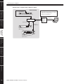
Scene
A combination of all configuration and preset parameters is called a “scene.”
Scenes can be recalled from an ICP1, GPI device, other external controllers, DME64N/DME24N, or computer.
Up to 999 scenes can be stored for each device group.
Scene structure
Scene change
16 x 8
Scene
Scene 1
Scene 2
Scene 999
Component
Configuration
Preset
Parameter
Ex.: Gate
• Attack
• Decay
• Range
• Threshold
• Key in
• Hold
Matrix Mixer
USB
PEAK
PEAK
SIGNAL
SIGNAL
PEAK
PEAK
SIGNAL
SIGNAL
PEAK
PEAK
SIGNAL
SIGNAL
INPUT
INPUT
DIGITAL MIXING ENGINE SATELLITE
USB
PEAK
PEAK
SIGNAL
SIGNAL
PEAK
PEAK
SIGNAL
SIGNAL
PEAK
PEAK
SIGNAL
SIGNAL
INPUT
INPUT
DIGITAL MIXING ENGINE SATELLITE
First Act Dark Change Second Act
Band Set
Play Set
Stage Stage Stage
Play
Set
Band
Set
Band Set
Play Set
Scene 1 Scene Recall Scene 2

Introduction to the DME Satellite
DME8i-C/DME8o-C/DME4io-C Owner’s Manual
Foreword
Introduction to
the DME Satellite
Controls and
Connectors
Connecting to
a Computer
Audio I/O
Connection
Connecting to an
External Device
Other Functions
References
12
Signal Types
DME Satellite audio system signals can be broadly categorized as follows.
Audio
Analog and digital signals are input and output between the DME Satellite, other DME series units, and other
audio devices.
Analog signals are input and output via the [INPUT]/[OUTPUT] jacks. Digital signals are input and output via
the CobraNet jacks.
Device group control
Device group control signals control all DME series devices in the group.
There are two types of device group control signals, as follows:
• Control signals between the computer and the group master DME series unit
• Control signals between the group master DME series unit and the other DME series
units
You can use the DME Designer application to control the entire device group, such as sending components to the
devices and setting the parameters as required.
Device control
These signals provide communication and control between individual devices.
Included in this category are MIDI messages transferred between [USB] connectors, GPI signals transferred be-
tween [GPI] connectors, and remote head amp control signals handled via the [REMOTE] connector.
Type of signals handled by the DME Satellite
Connector Audio Signal Device Control
Reference
Page
[USB] Connector —
• Control signals between computer and DME
Satellite
• MIDI messages
page 22
[NETWORK] Connector —
• Control signals between computer and DME
Satellite
• Control signals between DME Satellites
• Control signals with a controller such as an
AMX or Crestron
page 24
CobraNet Connector
Up to 16 channels of input
and output.
• Internal head amp control signals with a digital
mixer
• Control signals between PM5D and DME
Satellite.
page 32
[GPI] Connector —
GPI control signals between GPI device (GPI
controller, etc.) and DME series unit
page 34
[REMOTE] Connector —
• Control signals to/from an external device
(such as AD8HR head amplifier)
• Control signals for a digital mixer and internal
head amp
• Control signals with a controller such as an
AMX or Crestron
• MIDI messages
page 30
[INPUT]/[OUTPUT]
Connectors (audio in/out)
The number of I/O channels
depends on model.
— page 29
1
2
3

References
Other Functions
Connecting to an
External Device
Audio I/O
Connection
Connecting to
a Computer
Controls and
Connectors
Introduction to
the DME Satellite
Foreword
Introduction to the DME Satellite
DME8i-C/DME8o-C/DME4io-C Owner’s Manual
13
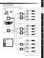
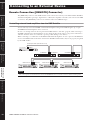
System Examples
Multiple DME Satellite units: Large-scale system
HOMEHOME UTILITYUTILITYSCENESCENE LEVELLEVEL MUTEMUTE
ENTERENTERCANCELCANCEL
USB
PEAK
PEAK
SIGNAL
SIGNAL
PEAK
PEAK
SIGNAL
SIGNAL
PEAK
PEAK
SIGNAL
SIGNAL
INPUT
INPUT
DIGITAL MIXING ENGINE SATELLITE
USB
PEAK
PEAK
SIGNAL
SIGNAL
PEAK
PEAK
SIGNAL
SIGNAL
PEAK
PEAK
SIGNAL
SIGNAL
INPUT
INPUT
DIGITAL MIXING ENGINE SATELLITE
USB
PEAK
PEAK
SIGNAL
SIGNAL
PEAK
PEAK
SIGNAL
SIGNAL
PEAK
PEAK
SIGNAL
SIGNAL
INPUT
INPUT
DIGITAL MIXING ENGINE SATELLITE
USB
PEAK
PEAK
SIGNAL
SIGNAL
PEAK
PEAK
SIGNAL
SIGNAL
PEAK
PEAK
SIGNAL
SIGNAL
INPUT
INPUT
DIGITAL MIXING ENGINE SATELLITE
USB
PEAK
PEAK
SIGNAL
SIGNAL
PEAK
PEAK
SIGNAL
SIGNAL
PEAK
PEAK
SIGNAL
SIGNAL
INPUT
INPUT
DIGITAL MIXING ENGINE SATELLITE
ICP1
Computer
Hub
Hub
Hub
Hub
Hub
Hub
Hub
Hub
DME64N
DME8i-C
DME8i-C
DME8i-C
DME8i-C
DME8o-C
DME8o-C
DME8o-C
DME8o-C
DME4io-C
DME8o-C
DME8i-C
Space B
Space A
Space C
Space D
Analog In
Analog In
Analog In
Analog In
Analog Out
Analog Out
Analog Out
Analog Out
Analog In
Analog In
Analog In
Analog Out
Analog Out
Ethernet
CobraNet
Ethernet Switching Hub
CobraNet Switching Hub
DME4io-C
Analog Out
MY16-CII × 3

Introduction to the DME Satellite
DME8i-C/DME8o-C/DME4io-C Owner’s Manual
Foreword
Introduction to
the DME Satellite
Controls and
Connectors
Connecting to
a Computer
Audio I/O
Connection
Connecting to an
External Device
Other Functions
References
14
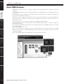
About DME Designer
DME Designer software enables you to integrate, configure, and control the DME series system from a connected
computer.
You can build the DME series audio system using graphic blocks in DME Designer that are displayed on the com-
puter monitor.
The DME series settings, configuration, and parameter data are transferred from the computer to the DME series
unit via the USB or Ethernet connection.
DME series settings, configuration, and parameter data is sent via USB or Ethernet to the connected DME series
unit. After the data is transmitted, you can disconnect the DME series unit from the computer and use it as an
independent processor.
You can also connect it to a computer and control it in realtime from DME Designer.
If multiple DME series units are connected in the network, DME Designer enables you to build a configuration
that includes those units.
Please download the DME Designer application, driver, DME setup manual, and DME Designer owner’s manual
at the following URL:
http://www.yamahaproaudio.com/
Refer to the “Connecting to a Computer” (page 22) for more information on connecting a computer to the DME
Satellite. For details on how to install DME Designer and the drivers that are required for connection, refer to the
“DME Setup Manual”.
Refer to the DME Designer Owner’s Manual for setup and operation instructions.

References
Other Functions
Connecting to an
External Device
Audio I/O
Connection
Connecting to
a Computer
Controls and
Connectors
Introduction to
the DME Satellite
Foreword
Introduction to the DME Satellite
DME8i-C/DME8o-C/DME4io-C Owner’s Manual
15
About CobraNet
CobraNet in a nutshell
Developed by Cirrus Logic, Inc., U.S., CobraNet technology allows real-time uncompressed digital audio distri-
bution over industry-standard Fast Ethernet (100 megabits/sec.) networks.
Up to 128 channels, 64 in each direction, can be carried simultaneously over a CobraNet network.
(The number of channels available depends on the performance of the devices and the condition of audio signals.)
CobraNet currently supports a 48 or 96 kHz sampling rate with 16, 20, or 24-bit resolution.
It can also transfer control data along with audio signals.
The type of control data that the network can handle depends on the type of devices on the network.
When an audio signal passes through the CobraNet network, it causes a fixed latency of 5.33 milliseconds (or,
depending on the setting, 2.67 or 1.33 milliseconds).
Visit the CobraNet home page for more information on CobraNet.
CobraNet home page
http://www.cobranet.info/
Bundle
CobraNet network transmits digital audio data in bundles. When bundles are received, they are converted back
into the original digital audio data.
With the DME Satellite, a single bundle can carry up to eight channels of digital audio.
For routing around the network, bundles are assigned numbers from 1 through 65,279. If you set the same bundle
number on both transmitting and receiving devices, digital audio data can be transmitted over CobraNet network.
There is no limitation to the number of bundles that can be transmitted and received over the CobraNet network,
as long as there are enough network resources.
The number of bundles that can be handled depends on the device.
The DME Satellite can use up to 4 output bundles and up to 8 input bundles.
You can specify the bundle number by using the DME Designer application.
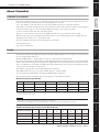
The maximum number of channels that can be assigned to each bundle is as follows.
Maximum channels per bundle
* Since 96-kHz audio is handled as two 48-kHz signals combined, the maximum number of channels is halved.
** The audio signal output from the 4th channel will include some aliasing noise, and proper operation cannot be guaranteed.
Please do not use this channel.
Number of bundles per channel and usable channels
Latency 16bit, 48kHz 20bit, 48kHz 24bit, 48kHz 16bit, 96kHz 20bit, 96kHz 24bit, 96kHz
5.33ms 8 8 7 4* 4* 3**
2.67ms 8 8 8 4* 4* 4*
1.33ms 8 8 8 4* 4* 4*
NOTE
The number of channels per bundled can be changes as shown below.
Depending on the configuration, the maximum number of channels that can be handle may be less than 8.
Channels per Bundle
Bundle
1
Bundle
2
Bundle
3
Bundle
4
Bundle
5
Bundle
6
Bundle
7
Bundle
8
8
1-8 9-16 – – – – – –
4
1–4 5–8 9–12 13–16 – – – –
2
1–2 3–4 5–6 7–8 9–10 11–12 13–14 15–16
1
12345678

Introduction to the DME Satellite
DME8i-C/DME8o-C/DME4io-C Owner’s Manual
Foreword
Introduction to
the DME Satellite
Controls and
Connectors
Connecting to
a Computer
Audio I/O
Connection
Connecting to an
External Device
Other Functions
References
16
Multicast and unicast bundles
CobraNet bundles can be either multicast or unicast.
Multicast bundles are transmitted from one device to multiple devices on the network (one-to-many). Unicast
bundles are transmitted from one device to another (one-to-one).
Unicast bundles are transmitted only when another device is configured to receive them by assigning the same
bundle numbers. On the other hand, multicast bundles are transmitted to all devices on the network regardless of
whether any devices are configured to receive them, and only devices that are configured to receive those bundles
actually process them.
It is recommended that no more than four multicast bundles (offering up to 32 channels) be used, since transmis-
sion of multicast bundles consumes more network resources.
Unicast bundles should be used if five or more bundles are required. It is also possible to set multiple devices to
receive the same unicast bundle number, and depending on the transmitting device up to 4 receiving devices may
be able to simultaneously receive the same bundle. This situation is known as “multi-unicast.” The DME Satellite
is capable of handling multi-unicast bundles.
Multicast and unicast bundles are identified by bundle number. Multicast bundles are numbered 1 through 255.
Unicast bundles are numbered 256 through 65,279.
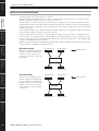
Multicast bundle
If Device A is transmitting multicast
bundles, they will be transmitted to
all devices on the CobraNet net-
work (e.g., Devices B, C, and D in
the example).
Unicast bundle
If Device A is transmitting unicast
bundles, and the same bundle num-
bers are assigned to the transmitting
bundles on Device A and receiving
bundles on Device D, then Device
A will transmit the unicast bundels
to Device D.
Network
AB
CD
CobraNet Device CobraNet Device
CobraNet Device CobraNet Device
Digital Audio Data
Network
AB
CD
CobraNet Device CobraNet Device
CobraNet Device CobraNet Device
Digital Audio Data

References
Other Functions
Connecting to an
External Device
Audio I/O
Connection
Connecting to
a Computer
Controls and
Connectors
Introduction to
the DME Satellite
Foreword
Introduction to the DME Satellite
DME8i-C/DME8o-C/DME4io-C Owner’s Manual
17
Conductors and performers
One device on the CobraNet network works as the conductor (network sync master). All other CobraNet devices
are performers (network sync slaves). Each device synchronizes its own internal clock to the beat packets (sync
signals) transmitted by the conductor.
The conductor device is chosen automatically and no user intervention is required.
However, setting an appropriate conductor priority could enable users to assign any device as the conductor.
Refer to the DME Designer Owner’s Manual for more information on setting the conductor priority.
If the DME Satellite is the conductor, the [IN USE/CONDUCTOR] LED flashes orange.
If the conductor fails, another device automatically takes over.
Since the conductor transmits beat packets (sync signals) onto the network, each performer does not require an
external word clock connection, reducing cabling complexity and cost.
Any non-networked digital audio equipment should derive its word clock from a CobraNet networked device.
Cables and hubs for CobraNet network
Category-5 metal cables can be used for runs of up to 100 meters. The maximum distance for multimode fiber
optic cable is 2 kilometers.
However, due to differences in cables, as well as switching hub and CobraNet device performance, proper opera-
tion at the maximum length cannot be guaranteed in all cases.
Always use switching hubs in a CobraNet network. When using metal cable for connections, be sure to use Cat-
egory 5 straight cables.
NOTE
All CobraNet networked devices, regardless of whether each device serves as the conductor or a performer, can receive digital
audio data and control data.

DME8i-C/DME8o-C/DME4io-C Owner’s Manual
Foreword
Introduction to
the DME Satellite
Controls and
Connectors
Connecting to
a Computer
Audio I/O
Connection
Connecting to an
External Device
Other Functions
References
18
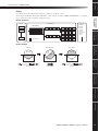
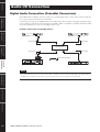
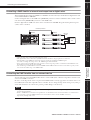
Front Panel
1 [USB] Connector
Use this connector to connect the DME Satellite to the com-
puter’s USB port. If you plan to use a USB connection, you
must first install the USB-MIDI Driver on your computer.
Refer to the “DME Setup Manual” (PDF file) for installa-
tion instructions.
Be sure to follow the procedure below when you make a USB
connection with a computer. Otherwise, the computer and/
or DME Satellite may freeze, resulting in damages or loss of
data.
If the computer or DME Satellite freezes, turn the power to
the DME Satellite off and then on, then restart the comput-
er.
2 [NETWORK] Indicator
Lights orange while data communication is occurring via the
[USB] or [NETWORK] connector.
3 [MASTER] Indicator
Lights green when the device is operating as the group mas-
ter. The indicator is turned off if the device is operating as a
slave.
You can assign the group master in DME Designer.
Controls and Connectors
USB
USB
USB
PEAK
PEAK
SIGNAL
SIGNAL
PEAK
PEAK
SIGNAL
SIGNAL
PEAK
PEAK
SIGNAL
SIGNAL
INPUT
PEAK
PEAK
SIGNAL
SIGNAL
PEAK
PEAK
SIGNAL
SIGNAL
PEAK
PEAK
SIGNAL
SIGNAL
PEAK
PEAK
SIGNAL
SIGNAL
PEAK
PEAK
SIGNAL
SIGNAL
PEAK
PEAK
SIGNAL
SIGNAL
INPUT
INPUT
DIGITAL MIXING ENGINE SATELLITE
DIGITAL MIXING ENGINE SATELLITE
DIGITAL MIXING ENGINE SATELLITE
92 5 7
3 4 86
92 5 7
3 4 86
92 5 7
3
1
1
1 4 86
DME8i-C
DME8o-C
DME4io-C
•Before you connect the DME Satellite to the computer
via USB, cancel the computer’s energy saving mode
(such as Suspend, Sleep, or Stand-by mode).
•Before turning on the power to the DME Satellite, first
connect its [USB] connector to the computer’s USB
port.
•Before turning the power to the unit on or off, and
before connecting or disconnecting the USB cable, take
the following actions:
-Quit all open applications.
-Make sure that the DME Satellite is NOT transferring
any data.
•Be sure to wait six seconds or more between turning the
power to the unit on and then off (or off and then on),
or between connecting and disconnecting (or vice versa)
the USB cable.
CAUTION

References
Other Functions
Connecting to an
External Device
Audio I/O
Connection
Connecting to
a Computer
Controls and
Connectors
Introduction to
the DME Satellite
Foreword
Controls and Connectors
DME8i-C/DME8o-C/DME4io-C Owner’s Manual
19
4 [ERROR] Indicator
Lights when an error occurs. The [PEAK] indicators reflect
the type of error. The [ERROR] indicator flashes when the
battery charge is getting low.
5 [IN USE/CONDUCTOR] Indicator
Lights orange when the power is supplied correctly to the
DME Satellite. It flashes while the device is operating as a
CobraNet conductor. If the secondary (backup) connector
on the DME Satellite is connected (page 21), the indicator
turns off every three seconds to indicate an abnormality on
the primary connection.
6 [LINK/ACTIVITY] Indicator
Lights up steadily or flashes slowly when cables are connect-
ed correctly to the CobraNet connectors. It flashes rapidly
while the unit is transferring data onto the network correctly.
If the secondary (backup) connection is being used for com-
munication, the indicator turns off every three seconds to in-
dicate an abnormality on the primary connection.
7 [PEAK] Indicators
Light red when the signal level at the corresponding built-in
analog audio inputs or outputs ([INPUT] or [OUTPUT]
connectors) reaches or exceeds -3 dBFS. They also indicate
an error number or status.
8 [SIGNAL] Indicators
Light green when the signal level at the corresponding built-
in analog audio inputs or outputs ([INPUT] or [OUTPUT]
connectors) reaches or exceeds -40 dBFS. They also indicate
the status, for example, of the initialization process.
9 [POWER] Switch
Turns mains power to the device on and off. The DME Sat-
ellite will start up with the same scene settings that were active
when it shut down. You can use the “Last Mem. Resume” set-
ting in DME Designer to set up the DME Satellite so that at
startup it will recall the scene selected before you turned off
the power to the device.
Caution when turning the
power off
Do not turn off the power while the front panel
[SIGNAL] indicators are lighting consecutively in
the clockwise direction.
This indicates that data is being written into internal mem-
ory, and part of the data may be damaged if you turn off the
power at this time. Data writing will occur during the fol-
lowing operations.
• While shifting to on-line operation
• While storing or recalling or deleting scene memory
• While saving changes to the Utility settings
• While using the DME File Storage function to transmit/
receive or delete files
• While updating the firmware, or while reverting to the
previous firmware following a failed update
NOTE
Refer to page 21 for information on the primary and secondary
connectors.
NOTE
Remove the transparent protective film that was applied to the
indicator panel prior to shipment from the factory.
•If “Last Mem. Resume” is set to ON, the unit will back
up data to the internal memory periodically. In this
case, do not turn off the power to the unit within five
(5) seconds after you operate any parameters.
CAUTION
Lights consecutively in
the clockwise direction

Controls and Connectors
DME8i-C/DME8o-C/DME4io-C Owner’s Manual
Foreword
Introduction to
the DME Satellite
Controls and
Connectors
Connecting to
a Computer
Audio I/O
Connection
Connecting to an
External Device
Other Functions
References
20
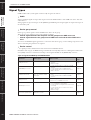
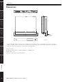
Rear Panel
1 [AC IN] Connector
Connect to the AC mains using the supplied AC power cord.
First connect the power cord to the DME Satellite, then in-
sert the power cord plug into an AC outlet.
2 Ground Screw
The supplied AC power cable is a 3-wire type, so if the AC
outlet used is properly earthed the DME Satellite will be
earthed as well. Hum and interference may by further re-
duced in some cases by also connecting the earth screw to an
earth point.
3 [NETWORK] Connector
This is a 100Base-TX/10Base-T Ethernet connector for con-
nection to a computer or to another DME series unit in the
network. See “Ethernet Connection ([NETWORK] Con-
nector)” on page 24 for connection details.
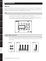
4 Dip Switch
This 6-bit dip switch enables you to select the [REMOTE]
connector function or initialize the DME Satellite, depend-
ing on its setting at the startup of the device. To switch be-
tween RS-232C and RS-422 for the [REMOTE] connector
function, turn off the power to the device, set the dip switch
as shown below, then turn on the power to the device again.
See page 35 for the DME Satellite initialization procedure.
RS-232C RS-422
5 [REMOTE] Connector
This 9-pin D-SUB connector allows connection to a Yama-
ha AD824 or AD8HR remote head amplifier or an RS-
232C/RS-422 compatible controller such as those from
AMX or Crestron. See “Remote Connection ([REMOTE]
Connector)” on page 30 for connection details.
RS-232C
RS-422
RS-232C
RS-422
RS-232C
RS-422
MAC ADD * XX XX XX XX XX XX *
MAC ADD * XX XX XX XX XX XX *
MAC ADD * XX XX XX XX XX XX *
9
1 3 4 5
2
1 3 4 5
2 )
1 3 4 5
2 )
97
8
6
7
8
6
7
8
6
DME8i-C
DME8o-C
DME4io-C
Even when the power switch is turned off,
electricity is still flowing to the product all the
minimum level. When you are not using the
product for a long time, make sure to unplug the
power cord from the wall AC outlet.
NOTE
Use a STP (Shielded Twisted Pair) cable for this connection to
prevent electromagnetic interference.
CAUTION
If you do not plan to initialize the DME Satellite,
set all dip switch bits (excluding one bit for the
RS-422 setting) in the upper position.
RS-232C
RS-422
RS-232C
RS-422
CAUTION
La pagina si sta caricando...
La pagina si sta caricando...
La pagina si sta caricando...
La pagina si sta caricando...
La pagina si sta caricando...
La pagina si sta caricando...
La pagina si sta caricando...
La pagina si sta caricando...
La pagina si sta caricando...
La pagina si sta caricando...
La pagina si sta caricando...
La pagina si sta caricando...
La pagina si sta caricando...
La pagina si sta caricando...
La pagina si sta caricando...
La pagina si sta caricando...
La pagina si sta caricando...
La pagina si sta caricando...
La pagina si sta caricando...
La pagina si sta caricando...
La pagina si sta caricando...
La pagina si sta caricando...
La pagina si sta caricando...
La pagina si sta caricando...
La pagina si sta caricando...
La pagina si sta caricando...
La pagina si sta caricando...
La pagina si sta caricando...
La pagina si sta caricando...
La pagina si sta caricando...
La pagina si sta caricando...
La pagina si sta caricando...
-
 1
1
-
 2
2
-
 3
3
-
 4
4
-
 5
5
-
 6
6
-
 7
7
-
 8
8
-
 9
9
-
 10
10
-
 11
11
-
 12
12
-
 13
13
-
 14
14
-
 15
15
-
 16
16
-
 17
17
-
 18
18
-
 19
19
-
 20
20
-
 21
21
-
 22
22
-
 23
23
-
 24
24
-
 25
25
-
 26
26
-
 27
27
-
 28
28
-
 29
29
-
 30
30
-
 31
31
-
 32
32
-
 33
33
-
 34
34
-
 35
35
-
 36
36
-
 37
37
-
 38
38
-
 39
39
-
 40
40
-
 41
41
-
 42
42
-
 43
43
-
 44
44
-
 45
45
-
 46
46
-
 47
47
-
 48
48
-
 49
49
-
 50
50
-
 51
51
-
 52
52


Yamaha DME4io Manuale del proprietario
- Categoria
- Mixer audio
- Tipo
- Manuale del proprietario
in altre lingue
- English: Yamaha DME4io Owner's manual
- français: Yamaha DME4io Le manuel du propriétaire
- español: Yamaha DME4io El manual del propietario
- Deutsch: Yamaha DME4io Bedienungsanleitung
- русский: Yamaha DME4io Инструкция по применению
- Nederlands: Yamaha DME4io de handleiding
- português: Yamaha DME4io Manual do proprietário
- dansk: Yamaha DME4io Brugervejledning
- čeština: Yamaha DME4io Návod k obsluze
- polski: Yamaha DME4io Instrukcja obsługi
- svenska: Yamaha DME4io Bruksanvisning
- Türkçe: Yamaha DME4io El kitabı
- suomi: Yamaha DME4io Omistajan opas
- română: Yamaha DME4io Manualul proprietarului
Documenti correlati
-
Yamaha DME8i Manuale del proprietario
-
-
-
Yamaha DME64N - Pro Audio Manuale utente
-
-
-
-
-
-
