
G
B
I
T
E
S
F
R
D
E
N
L
P
T
G
R
CH55EPA (S)/CH55EPA (SM)
CH55EPB (S)/CH55EPB (SM)
CH55EPC (S)/CH55EPC (SM)
Owner’s manual
Mode d emploi
Manuale d istruzioni
Bedienungsanleitung
Manual del propietario
Gebruiksaanwijzing
Manual do propriet rio
∆ΗΓΙΕΣ ΡΗΣΗΣ
970-83801-200 2007.05

GB-1
G
B
Owner’s manual
Read the manual carefully before
operating this machine.
CH55EPA (S)/CH55EPA (SM)
CH55EPB (S)/CH55EPB (SM)
CH55EPC (S)/CH55EPC (SM)

GB-2
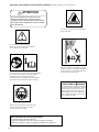
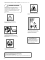
The engine exhaust from this product contains
chemicals known to the State of California to cause
cancer, birth defects and other reproductive harm.
It is important that you read, fully understand and observe
the following safety precautions and warnings. Careless
or improper use of the unit may cause serious or fatal
injury.
Read, understand and follow all warnings and
instructions in this manual and on the unit.
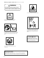
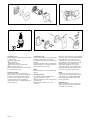
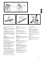
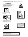
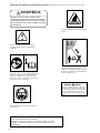
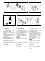
Meanings of symbols or labels.
(NOTE! Some units do not carry them)
Always wear eye, head and ear protectors when
using this unit.
Do not touch the blade when running the engine.
Keep all children, bystanders and helpers 15m
away from the unit. If anyone approaches you,
stop the engine and cutting attachment imme-
diately.
15m
All overhead electrical conductors and
communications wires can have electricity
flow with high voltages. Never touch wires
directly or indirectly when trimming, otherwise
serious injury or death may result.
WARNING DANGER
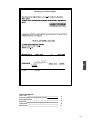
Read the manual carefully.
Check that the cutting equipment is correctly assembled and adjusted.
Start the unit and check the carburetor adjustment. See "Maintenance".
Before using your machine
WARNING

GB-3
G
B
What is what?
Warnings and safety instructions
Assembly procedures
Operating procedures
Maintenance
Specifications
4
5
6
7
9
12
Index
Declaration of conformity

GB-4
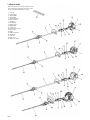
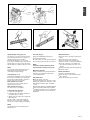
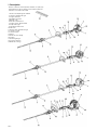
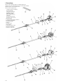
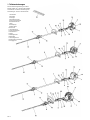
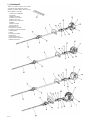
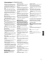
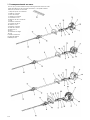
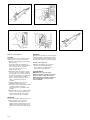
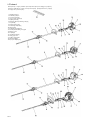
1. What is what?
1. Fuel cap
2. Throttle trigger
3. Starter handle
4. Speed limiter
5. Cutting attachment
6. Drive shaft tube
7. Handle bar
8. Priming pump
9. Ignition switch
10. Cutting blade
11. Throttle lock
12. Throttle trigger lookout
13. Choke lever
14. Engine
15. Angle transmission
16. Handle grip
17. Gear case
18. Blade cover
19. Suspension eyelet
Since this manual covers several models, there may
be some difference between pictures and your unit.
Use the instructions that apply to your unit.

GB-5
G
B
Always wear head protection with full face
shield to help protect against falling branches
and debris.
Avoid all power lines. This unit is not insulated
against electrical current.
Gloves should be used when sharpening
blades.
Always wear heavy, long pants, boots and
gloves. Do not wear loose clothing, jewelry,
short pants, sandals or go barefoot. Secure
hair so it is above shoulder length.
Do not operate this tool when you are tired, ill
or under the influence of alcohol, drugs or
medication.
Never let a child or inexperienced person
operate the machine.
Wear hearing protection.
Never start or run the engine inside a closed
room or building. Breathing exhaust fumes
can kill.
Keep handles free of oil and fuel.
Keep hands away from cutting equipment.
Do not grab or hold the unit by the cutting
equipment.
When the unit is turned off, make sure the
cutting attachment has stopped before the unit
is set down.
When operation is prolonged, take a break
from time to time so that you may avoid
possible whitefinger disease which is caused
by vibration.
The operator must obey the local regulations
of cutting area.
Inspect the entire unit/machine before each
use. Replace damaged parts. Check for fuel
leaks and make sure all fasteners are in place
and securely tightened.
Replace parts that are cracked, chipped or
damaged in any way before using the
unit/machine.
Keep others away when making carburetor
adjustments.
Use only accessories as recommended for
this unit/machine by the manufacturer.
Never let the blade strike any obstacle.
If the blade makes contact, the machine
should be stopped and checked carefully.
All unit service, other than the items listed in
the operator’s/owner’s manual, should be
performed by competent machine service
personnel. (For example, if improper tools are
used to remove the flywheel or if an improper
tool is used to hold the flywheel in order to
remove the clutch, structural damage to the
flywheel could occur and could subsequently
cause the flywheel to burst.)
Move at least 3 m away from fueling site before
starting engine.
Stop engine before removing fuel cap.
Empty the fuel tank before storing the
unit/machine. It is recommended that the fuel
be emptied after each use. If fuel is left in the
tank, store so fuel will not leak.
Store unit/machine and fuel in area where fuel
vapors cannot reach sparks or open flames
from water heaters, electric motors or switches,
furnaces. etc.
Mix and pour fuel outdoors and where there are
no sparks or flames.
Use a container approved for fuel.
Do not smoke or allow smoking near fuel or the
unit/machine or while using the unit/machine.
Wipe up all fuel spills before starting engine.
Fuel safety
Unit / machine safety
Do not cut any material other than leaves or
small brunches objects.
For respiratory protection, wear an aerosol
protection mask when cutting the leaves after
insecticide has been applied.
Keep others including children, animals,
bystanders and helpers outside the 15 m
hazard zone. Stop the engine immediately if
you are approached.
Hold the unit/machine firmly with both hands.
Keep firm footing and balance. Do not over-
reach.
Keep all parts of your body away from the
muffler and cutting attachment when the
engine is running.
Before pruning branches, the operator must
be accustomed to the pruning techniques of
the machine.
Be sure to pre-plan a safe exit from falling
objects.
While cutting, hold the machine firmly with
both hands with thumb firmly locked around
front handle, and stand with feet well balanced
and your body balanced.
Cutting safety
Maintain the unit/machine according to
recommended procedures.
Disconnect the spark plug before performing
maintenance except for carburetor adjustments.
Keep others away when making carburetor
adjustments.
Use only genuine HITACHI replacement parts
as recommended by the manufacturer.
Maintenance safety
2. Warnings and safety instructions
Operator safety
WARNING!
Never modify the unit/machine in any way.
Do not use your unit/machine for any job
except that for which it is intended.
WARNING!
Antivibration systems do not guarantee that
you will not sustain whitefinger disease or
carpal tunnel syndrome. Therefore, continual
and regular users should monitor closely the
condition of their hands and fingers. If any of
the above symptoms appear, seek medical
advice immediately.
Carry the unit/machine by hand with the
engine stopped and the muffler away from
your body.
Allow the engine to cool, empty the fuel tank,
and secure the unit/machine before storing or
transporting in a vehicle.
Empty the fuel tank before storing the
unit/machine, It is recommended that the fuel
be emptied after each use. If fuel is left in the
tank, store so fuel will not leak.
Store unit/machine out of the reach of
children.
Clean and maintenance the unit carefully and
store it in a dry place
Make sure engine switch is off when
transporting or storing.
When transporting in a vehicle, cover blade
with blade cover.
Transport and storage
WARNING!
Indicates a strong possibility of severe
personal injury or loss of life, if instructions
are not followed.
CAUTION!
Indicates a possibility of personal injury or
equipment damage, if instructions are not
followed.
NOTE!
Helpful information for correct function and
use.
CAUTION!
Do not disassemble the recoil starter. You may
get a possibility of personal injury with recoil
spring.
If situations occur which are not covered in this
manual, take care and use common sense.
Contact HITACHI dealer if you need assistance.
Pay special attention to statements preceded
by the following words:

GB-6
Fig.1-2B
1
3
2
2
Fig.1-2
1
2
3
Fig.1-1
1
Fig.1-3
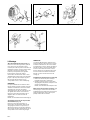
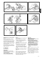
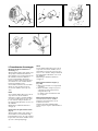
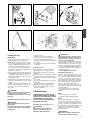
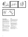
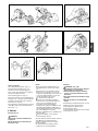
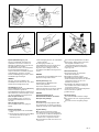
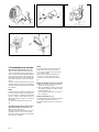
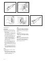
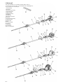
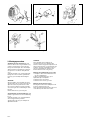
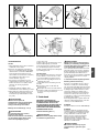
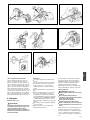
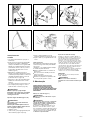
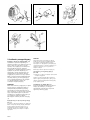
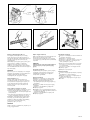
3. Assembly procedures
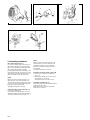
Drive shaft to engine (Fig. 1-1)
Loosen tube locking bolt (1) about ten turns so
that the bolt point will not obstruct drive shaft
tube to be inserted. When inserting drive shaft
tube, hold the tube locking bolt outward
preventing inside fitting from obstructing as well.
Insert the drive shaft into the clutch case of the
engine properly until the marked position (2) on
the drive shaft tube meets the clutch case.
NOTE!
When it is hard to insert drive shaft up to the
marked position on the drive shaft tube, turn
drive shaft by the cutter mounting end clockwise
or counter-clockwise. Tighten tube locking bolt
lining up the hole in the shaft tube.
Then tighten clamp bolt securely (3).
Cutting attachment to drive shaft (Fig. 1-2)
Loosen tube locking bolt (1).
Insert the drive shaft into the gear case of the
attachment properly until the marked position (2)
on the drive shaft tube meets the gear case.
NOTE!
When it is hard to insert drive shaft up to the
marked position on the drive shaft tube, turn
attachment clockwise or counter-clockwise.
Tighten tube locking bolt lining up the hole in
the shaft tube.
Then tighten clamp bolt securely (3).
Installation of support handle (1) (Fig.1-2B)
1. Remove 2pcs of hex. hole screw (2) from
gear case.
2. Install support handle (1) onto gear case by
removed hex. hole screws (2).
Then tighten hex. hole screws securely.
Installation of handle (Fig. 1-3)
Attach the handle to the drive shaft tube with the
angle towards the engine.
Adjust the location to the most comfortable
position before operation.

GB-7
G
B
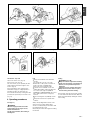
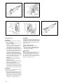
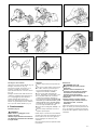
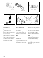
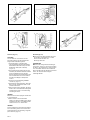
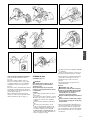
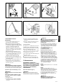
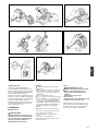
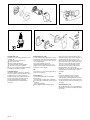
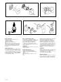
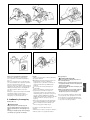
Throttle wire / stop cord
Remove air cleaner cover. (Fig. 1-4)
Connect stop cords. (Fig. 1-5)
Set outer-receiver (1) (If so provided) into wire
guide and put throttle wire through the outer-
receiver. (Fig.1-4)
Connect throttle wire end to carburetor and
install swivel cap (2) (if so equipped) where is
included in tool bag, onto swivel (Fig. 1-6)
Cover throttle wire and stop cords together with
protective tube provided up to air cleaner cover.
(Fig. 1-7)
Fig. 1-7
Fig. 1-5Fig. 1-4
1
Fig.2-1 Fig.2-1B
1
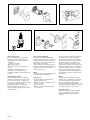
Always use branded 89 octane unleaded
gasoline.
Use genuine two-cycle oil or use a mix
between 25:1 to 50:1, please consult the oil
bottle for the ratio or HITACHI dealer.
Only for the state of California at 50:1.
If genuine oil is not available, use an anti-
oxidant added quality oil expressly labeled for
air-cooled 2-cycle engine use(JASO FC
GRADE OIL or ISO EGC GRADE). Do not use
BIA or TCW (2-stroke water-cooling type)
mixed oil.
Never use multi-grade oil (10 W/30) or waste
oil.
Always mix fuel and oil in a separate clean
container.
Always start by filling half the amount of fuel,
which is to be used. Then add the whole
amount of oil. Mix (shake) the fuel mixture. Add
the remaining amount of fuel.
Mix (shake) the fuel-mix thoroughly before filling
the fuel tank.
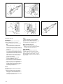
4. Operating procedures.
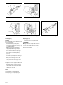
Fuel (Fig. 2-1)
This unit is equipped with a two-stroke
engine. Always run the engine on fuel,
which is mixed with oil.
Provide good ventilation, when fueling or
handling fuel.
Fuel
Before fueling, clean the tank cap area carefully,
to ensure that no dirt falls into the tank. Make sure
that the fuel is well mixed by shaking the container,
before fueling.
Always shut off the engine before refueling.
Slowly open the fuel tank (1), when filling up
with fuel, so that possible overpressure
disappears.
Tighten the fuel cap carefully, after fueling.
Always move the unit at least 3 m (10 ft.)
from the fueling area before starting.
Fueling
WARNING!
WARNING! (Fig.2-1B)
Fig. 1-6

GB-8
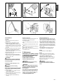
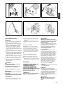
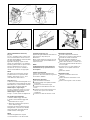
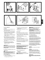
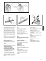
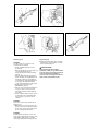
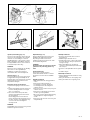
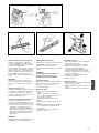
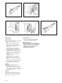
Starting (Fig. 2-5)
CAUTION!
Before starting, make sure the cutting attachment
does not touch anything.
1. Set ignition switch (1) to ON position.
* Push priming bulb (4) several times so that
fuel flows through the bulb or return pipe. (If
so equipped) (Fig. 2-6, 7)
2. With the safety trigger (2) pressed (if so
equipped), pull throttle trigger and push
throttle lock (3), then slowly release the
throttle trigger first, then the safety trigger.
This will lock the throttle in starting position.
3. Set choke lever to CLOSED position (5).
(Fig. 2-7)
4. Pull recoil starter briskly, taking care to keep
the handle in your grasp and not allowing it
to snap back.
5. When you hear the engine want to start,
return choke lever to RUN position (open).
Then pull recoil starter briskly again.
NOTE!
If engine does not start, repeat procedures from
2 to 5.
6. After starting engine, pull throttle trigger to
release throttle lock. Then allow the engine
about 2-3 minutes to warm up before
subjecting it to any load.
NOTE!
Throttle limiter (4) is to adjust maximum
opening of throttle. At the factory it is adjusted
at its full opening. (If so equipped) (Fig. 2-5)
Stopping (Fig. 2-8)
Decrease engine speed and run at an idle for
a few minutes, then turn off ignition switch.
WARNING!
A cutting attachment can injure while it continues
to spin after the engine is stopped or power
control is released. When the unit is turned off,
make sure the cutting attachment has stopped
before the unit is set down.
Fig.2-5
1
3
4
Fig.2-6
2
4
Fig.2-8Fig.2-7
4
5
5

GB-9
G
B
15m
3
1
Fig.2-11Fig.2-10Fig.2-9
15m
(50ft.)
Fig.2-12
Fig. 3-1
T
T
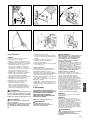
CAUTION!
Always wear gloves during operation or
maintenance.
Review the area to be trimmed. Look for
hazards that could contribute to unsafe
conditions. DO NOT operate unit if any wires
(power, telephone, cable, etc.) are closer than
15M (50ft.) to any part of the operator or unit.
(Fig. 2-9)
Spectator and fellow workers must be warned,
and children and animals prevented from
coming nearer than 15M (50ft.) while the pole
saw is in use. (Fig. 2-10)
Avoid all power lines. This unit is not insulated
against electrical current.
Always wear head protection with full face
shield to help protect against falling branches
and debris. (Fig. 2-10)
WARNING!
During operation, hold the unit firmly with
both hands. A single hand operation may
cause serious injury.
Adjustment of blade angle (Fig. 2-11,12)
WARNING!
Always stop engine before making
adjustments.
Never touch the blade when adjusting blade
angle. Hold the support handle (3) instead.
1. Stop the engine.
2. Loosen handle knob (1) slightly so that the
support handle (3) slides.
3. Adjust the blade angle to desired position by
holding the support handle (3).
4. Then, finger-tighten the handle knob (1)
securely.
SAFE OPERATION
Trimming techniques
This unit is designed for trimming hedges and
small branches. Follow these tips for
successful operation.
Plan cut carefully. Check direction branch will
fall.
Long branches should be trimmed in several
pieces.
Do not stand directly beneath branch being cut.
Apply a light cutting pressure.
Ease cutting pressure when nearing end of cut
to maintain control.
5. Maintenance
MAINTENANCE, REPLACEMENT, OR REPAIR
OF THE EMISSION CONTROL DEVICES AND
SYSTEMS MAY BE PERFORMED BY ANY
NON-ROAD ENGINE REPAIR
ESTABLISHMENT OR INDIVIDUAL.
Carburetor adjustment (Fig. 3-1)
WARNING!
The cutting attachment may be spinning
during carburetor adjustments.
WARNING!
Never start the engine without the complete
clutch cover and tube assembled! Otherwise
the clutch can come loose and cause
personal injuries.
In the carburetor, fuel is mixed with air. When the
engine is test run at the factory, the carburetor is
basically adjusted. A further adjustment may be
required, according to climate and altitude. The
carburetor has one adjustment possibility:
T = Idle speed adjustment screw.
Idle speed adjustment (T)
Check that the air filter is clean. When the idle
speed is correct, the cutting attachment will not
rotate. If adjustment is required, close (clockwise)
the T-screw, with the engine running, until the
cutting attachment starts to rotate. Open (counter-
clockwise) the screw until the cutting attachment
stops. You have reached the correct idle speed
when the engine runs smoothly in all positions
well below the rpm when the cutting attachment
starts to rotate.
If the cutting attachment still rotates after idle
speed adjustment, contact HITACHI dealer.
NOTE!
Standard Idle rpm is 2500~3000 rpm.
NOTE!
Some models sold areas with strict exhaust
emission regulation do not have high and low
speed carburetor adjustments. Such
adjustments may allow the engine to be
operated outside of their emission compliance
limits. For these models, the only carburetor
adjustment is idle speed.
WARNING!
When the engine is idling the cutting
attachment must under no circumstances
rotate.

GB-10
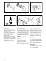
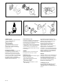
Air filter (Fig. 3-2)
The air filter must be cleaned from dust and dirt
in order to avoid:
Carburetor malfunctions.
Starting problems.
Engine power reduction.
Unnecessary wear on the engine parts.
Abnormal fuel consumption.
Clean the air filter daily or more often if working
in exceptionally dusty areas.
Cleaning the air filter
Remove the air filter cover and the filter (1).
Rinse it in warm soap suds. Check that the filter
is dry before reassembly. An air filter that has
been used for some time cannot be cleaned
completely. Therefore, it must regularly be
replaced with a new one. A damaged filter must
always be replaced.
Fig.3-2
1
1
Fig. 3-2B
Fig.3-3 Fig.3-4
Fuel filter (Fig. 3-2B)
Drain all fuel from fuel tank and pull fuel filter line
from tank. Pull filter element out of holder
assembly and rinse element in warm water with
detergent.
Rinse thoroughly until all traces of detergent are
eliminated. Squeeze, do not wring, away excess
water and allow element to air dry.
NOTE!
If element is hard due to excessive dirt build-up,
replace it.
Spark plug (Fig. 3-3)
The spark plug condition is influenced by:
An incorrect carburetor setting.
Wrong fuel mixture (too much oil in the gasoline)
A dirty air filter.
Hard running conditions (such as cold
weather).
These factors cause deposits on the spark plug
electrodes, which may result in malfunction and
starting difficulties. If the engine is low on
power, difficult to start or runs poorly at idling
speed, always check the spark plug first. If the
spark plug is dirty, clean it and check the
electrode gap. Readjust if necessary. The
correct gap is 0.6 mm. The spark plug should
be replaced after about 100 operation hours or
earlier if the electrodes are badly eroded.
NOTE!
In some areas, local law requires using a
resistor spark plug to suppress ignition signals.
If this machine was originally equipped with
resistor spark plug, use same type of spark
plug for replacement.
Muffler (Fig. 3-4)
Remove the muffler and clean out any excess
carbon from the exhaust port or muffler inlet
every 100 hours of operation.

GB-11
G
B
Cylinder (Engine cooling) (Fig. 3-5)
The engine is air cooled and air must circulate
freely around engine and over cooling fins on
cylinder head to prevent overheating.
Every 100 operating hours, or once a year
(more often if conditions require) clean fins and
external surfaces of engine of dust, dirt and oil
deposits which can contribute to improper cooling.
NOTE!
Do not operate engine with engine shroud or
muffler guard removed as this will cause
overheating and engine damage.
Cutter blade (Fig. 4-1, 2)
The blades are installed to the cutter guide with
three to five bolts depending on cutter length.
Those bolts are tightened with a clearance so
that the cutters can move smoothly.
When clearance is too small:
The cutters do not move properly and the
sliding surfaces may seize.
When clearance is too large:
The cutters are poor in sharpness.
To adjust the cutter clearance:
1. Loosen the cutter fixing nuts.
2. Fully tighten the cutter fixing bolts and then
loosen them approx. 1/2 turn.
3. With the bolts set at that position, tighten the
cutter fixing nuts.
Be sure to replace cutter guide fixing bolts
when they are loosened, worn or damaged.
Also be sure to replace damaged cutter blade.
NOTE!
Properly lubricate the cutter sliding surfaces
with machine oil.
Gear case (Fig. 4-3)
Apply good quality lithium based grease
through the grease fittings.
On some models, one of the grease fittings has
been moved from upper location to the bottom.
NOTE!
Lubrication should be applied at 50 hour
intervals and more frequent at heavy use.
Maintenance schedule
Below you will find some general maintenance
instructions. For further information please
contact HITACHI dealer.
Daily maintenance
Clean the exterior of the unit.
Check the blade guard for damage or cracks.
Change the guard in case of impacts or cracks.
Check that the blade is sharp, and without
cracks.
Check that the blade nut is sufficiently tightened.
Make sure that the blade transport guard is
undamaged and that it can be securely fitted.
Check that nuts and screws are sufficiently
tightened.
Fig.3-5
Fig. 4-1 Fig. 4-2 Fig. 4-3
Weekly maintenance
Check the starter, especially cord and return
spring.
Clean the exterior of the spark plug.
Remove it and check the electrode gap.
Adjust it to 0.6 mm, or change the spark plug.
Clean the cooling fins on the cylinder and
check that the air intake at the starter is not
clogged.
Check that the angle gear is filled with grease.
Clean the air filter.
Monthly maintenance
Rinse the fuel tank with gasoline.
Clean the exterior of the carburetor and the
space around it.
Clean the fan and the space around it.

GB-12
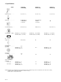
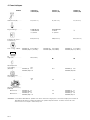
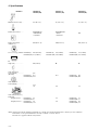
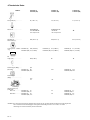
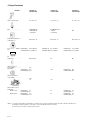
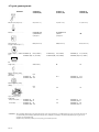
Engine Size (ml) ..................
Spark Plug ...........................
Fuel Tank Capacity ( l ).........
Dry Weight (kg).... 550mm.....
Overall cutter
length (mm)..........................
Sound pressure
level (dB(A)) ........................
(EN 27917)
Sound power
level (dB(A)) .........................
Vibration level (m/s
2
)
(ISO 7916)
Front handle..............
Rear handle...............
2.7
3.1
4.4
4.6
4.2
8.1
4.0
7.9
3.8
11.0
NOTE : Equivalent noise level/vibration level are calculated as the time-weighted energy total for noise/vibration levels under various working
conditions with the following time distribution : 1/2 idle, 1/2 racing.
*All data subject to change without notice.
6. Specifications
MODEL CH55EPB (S)
CH55EPB (SM)
CH55EPC (S)
CH55EPC (SM)
LwA
112
LpA
93.1
91.0
116
CH55EPA (S)
CH55EPA (SM)
CH55EPB (S)
CH55EPB (SM)
CH55EPC (S)
CH55EPC (SM)
CH55EPA (S)
CH55EPA (SM)
CH55EPB (S)
CH55EPB (SM)
CH55EPA (S)
CH55EPA (SM)
CH55EPB (S)
CH55EPB (SM)
CH55EPA (S)
CH55EPA (SM)
CH55EPB (S)
CH55EPB (SM)
CH55EPA (S)
CH55EPA (SM)
27 (1.65 cu. in.) 21 (1.28 cu. in.)
CHAMPION CJ8Y
or RCJ8Y
or equivalent
0.50 (16.9 fl. oz)/ 0.67(22.8 fl. oz) 0.43 (14.6 fl. oz)
6.36 (14.02 lbs)
5.7 (12.56 lbs)
5.7 (12.56 lbs)
5.4 (11.90 lbs)
93.2
96.5
112
24 (1.46 cu. in.)
CHAMPION CJ8
or NGK BMR-6A
or equivalent
550 (21.65 in)
6.3 (13.88 lbs)
5.9 (13.00 lbs)
88.1

FR-1
F
R
Mode d emploi
Lire attentivement le manuel avant
d utiliser la machine.
CH55EPA (S)/CH55EPA (SM)
CH55EPB (S)/CH55EPB (SM)
CH55EPC (S)/CH55EPC (SM)

FR-2
II est essentiel que vous lisiez et compreniez parfaitement
les consignes de sécurités et autres avertissements
suivants et que vous les observiez strictement.
L'utilisation inattentive ou inadéquate de cette machine
risque de provoquer des blessures graves ou fatales.
Lisez, comprenez et suivez toutes les
instructions et tous les avertissements donnés
dans ce manuel et sur le produit.
Signification des symboles ou des étiquettes.
(REMARQUE : Certains ensembles n'en sont pas pourvus)
Utilisez toujours des lunettes de protection ainsi
qu'une protection pour la tête et les oreilles
lorsque vous utilisez ce produit.
Ne touchez en aucun cas les lames quand le
moteur fonctionne.
Maintenir les enfants, les badauds et les aides
a plus de 15 mètres de l'ensemble. Si quelqu'un
s'approche de vous, couper immédiatement le
moteur et arrêter l'outil de coupe.
15m
Les gaz d'échappement du moteur de cette
machine contiennent des produits chimiques
considérés comme pouvant entraîner des cancers,
des malformations congénitales et autres troubles
de la reproduction.
ATTENTION!
II se peut que tous les conducteurs électriques
et tous les fils de télécommunications aériens
transportent du courant électrique à haute
tension. Ne jamais toucher directement ou
indirectement les fils lors de la taille. Dans
le cas contraire, des blessures graves ou la
mort pourraient en résulter.
AVERTISSEMENT DANGER
Lire attentivement le manuel d'utilisation.
Vérifier que l'équipement de coupe est monté et réglé correctement.
Démarrer la machine et vérifier le réglage du carburateur. Voir "Entretien".
Avant l'utilisation de votre nouvelle machine

FR-3
F
R
Description
Pr cautions et consignes de s curit
Montage
Utilisation
Entretien
Caract ristiques
4
5
6
7
9
12
Index

FR-4
1. Description
1. Bouchon de remplissage du carburant
2. Levier de commande des gaz
3. Poignée de lanceur
4. Régulateur de vitesse
5. Outil de coupe
6. Tube de de trans-mission
7. Poignée arceau / Guidon double
8. Pompe d'amorçage
9. Interrupteur marche-arrêt
10. Filtre à air
11. Blocage de la commande des gaz
12. Levier de sécurité
13. Levier de starter
14. Moteur
15. Boîtier de renvoi d'angle
16. Poignée
17. Boîte d'engrenages
18. Protecteur de lames
19. Oeillet d'accrochage
Comme ce manuel se réfère à plusieurs modèles, il se peut qu'il y
ait des différences entre les images et votre machine. Suivez les
instructions concernant votre modèle.

FR-5
F
R
II faut porter toujours un casque de protection
muni d'une visière de sécurité au complet pour
pouvoir assurer la protection contre la chute
de branches et de débris.
Éviter toutes les lignes d'énergie. Cette machine
n'est pas isolée contre le courant électrique.
Vous devez toujours porter des gants de
protection lorsque vous affûter la lame.
Portez toujours un pantalon, des chaussures
et des gants de sécurité. Evitez les vêtements
amples, les shorts, les sandales et les pieds
nus. Veillez à ce que vos cheveux ne
descendent pas au-dessous des épaules.
N’utilisez cette machine que si vous êtes en
pleine possession de vos moyens physiques.
Evitez strictement la consommation d’alcool,
de drogue ou de médicaments.
Ne jamais laisser un enfant ou une personne
inexpérimentée se servir de ces machines,
Portez un dispositif de proteclion contre le
bruit pour vos oreilles.
Ne mettez jamais le moteur en marche dans
un local clos, les gaz d'échappement étant
toxiques.
Nettoyez les poignées de toute trace d'huile
ou de carburant.
N'approchez jamais les mains du guide-
chaîne et de la chaîne,
Ne jamais attraper, ni tenir la machine par
l'extrémité du guide-chaîne.
Après l'arrêt de la tronçonneuse, attendez
l'arrêt complet de la chaîne de coupe avant de
poser la machine.
Lors d'une utilisation prolongée, veillez à faire
une pause périodiquement, afin d'éviter des
troubles éventuels provoqués par les
vibrations.
L'utilisateur de la machine doit se conformer
aux réglementations locales de la région dans
laquelle il effectue le travail.
Faites le mélange et le plein à l'air libre, à
distance de toute étincelle ou flamme
Utilisez pour l'essence un récipient agréé.
Ne fumez pas et ne laissez personne fumer à
proximité du carburant ou de la machine.
ni lorsque vous utilisez la machine.
Essuyez soigneusement toutes les traces de
carburant avant de mettre le moteur en
marche.
Pour démarrer la tronçonneuse, écartez vous
d'au moins 3 mètres de l'endroit où vous avez
fait le plein.
Arrêtez le moteur avant de dévisser les
bouchons des réservoirs de carburant ou
d'huile.
Vidangez le réservoir de carburant avant de
remiser la machine II est en fait recommandé de
le faire après chaque utilisation. Si le réservoir
n'est pas vide, rangez alors la machine dans
une position telle que le carburant ne risque pas
de couler.
Rangez la machine et le carburant dans un
endroit où les vapeurs d'essence ne risquent
pas d'entrer en contact avec des étincelles ou
une flamme en provenance d'un chauffe-eau,
d'un moteur électrique, d'un commutateur,
d'une chaudière, etc.
d'accidents ou de blessures.
Sécurité au niveau du carburant
Contrôlez entièrement votre machine avant
chaque utilisation. Remplacez les pièces
endommagées. Vérifiez l'absence de fuites de
carburant et assurez-vous que tous les
dispositifs de fixation sont en place et
solidement fixés.
Remplacez les éléments Tanaka de la
machine qui présentent des fissures, des
ébréchures ou toute autre avarie.
Ne laissez personne s'approcher lorsque vous
réglez le carburateur.
Utilisez uniquement les accessoires
recommandés par le constructeur pour cette
machine.
Ne jamais laisser les lames frapper contre un
obstacle quelconque. Si les lames rencontrent
un obstacle, il est nécessaire d'arrêter le
fonctionnement de la machine et de l'inspecter
soigneusement pour voir si elle n'est pas
endommagée.
Tous les travaux employant ce dispositif, outre
que les rubriques indiquées dans ce manuel,
doivent être effectués par un personnel apte à
employer la machine. (Par exemple, si on
emploie des outils incorrects pour extraire le
volant du moteur ou si on utilise un outil
incorrect pour maintenir le volant du moteur,
afin de retirer l'embrayage, il se peut qu’un tel
procédé entraîne une avarie structurale du
volant du moteur et provoque ensuite
l'éclatement de celui-ci.
Règles de sécurité concernant l'utilisation de
la machine.
Sécurité au niveau de la coupe
Entretenez votre machine selon les
recommandations du constructeur,
Débranchez la bougie avant toute intervention
intervention d'entretien, à l'exception des
opérations de réglages du carburateur.
Ne laissez personne s'approcher de la
machine lorsque vous procédez au réglage du
carburateur.
N’utilisez que les pièces de remplacement
HITACHI d’origine comme recommandé par le
fabricant.
Sécurité au niveau de l'entretien
Ne pas couper de matériel autrement que les
feuilles ou les petits objets de branches
Pour la protection respiratoire, porter un
masque de protection d'aérosol en coupant
les feuilles après l'insecticide ont été
appliquées.
Veillez à ce que personne, enfants, animaux,
spectateurs ou aides ne se tienne à l'int
érieur
d
'une zone de s
écurité de 15 mètres. Arr
ê
tez
immédiatement le moteur si quelqu
'un
s'approche de vous.
Maintenez fermement la machine des deux mains.
Tenez toujours le moteur à votre droite.
Tenez vous bien en équilibre sur vos deux
jambes. Ne travaillez jamais en porte-à-faux.
Demeurez toujours éloigné du silencieux
d'échappement et de l'ensemble de coupe
lorsque le moteur est en fonctionnement.
Avant de tailler une haie, l'utilisateur devra se
familiariser avec les techniques de taille à
l'aide d’une telle machine.
Avant de tailler, s'assurez de l'existence d'un
abri sûr à proximité.
Au cours d'une opération de taille, maintenir la
machine fermement des deux mains avec le
pouce bien bloqué autour de la poignée avant
et les pieds bien stables au sol.
2. Précautions et consignes de sécurité
Sécurité de l'utilisateur
ATTENTION!
Ne modifiez en aucun cas la machine.
N'utilisez jamais la tronçonneuse pour tout
autre tâche que celles auxquelles elle est
destinée.
ATTENTION!
Les systèmes anti-vibrations, aussi bon
soient-ils, ne garantissent pas que vous ne
puissiez pas souffrir de la maladie des
doigts blancs, ni du syndrome du canal
carpien. Par conséquent, si vous vous
servez de façon régulière et continue de
votre tronçonneuse, surveillez
soigneusement l'état de vos mains et de vos
doigts. Si l'un des symptômes ci-dessus
venait à apparaître, il serait indispensable
de vous faire examiner immédiatement par
votre médecin.
Remisez la machine hors de portée des
enfants.
Nettoyez soigneusement la tronçonneuse
avant de l'entreposer dans un endroit sec et
aéré.
Assurez vous que le commutateur d'arrêt du
moteur est bien sur la position "stop" lors du
transport ou du remisage de la machine.
Lors du transport dans un véhicule, couvrir la
lame du capot.
ATTENTION!
Information de première importance pour éviter
des dommages corporels graves ou mortels.
IMPORTANT!
Information importante afin d'éviter les
dommages corporels ou matériels.
REMARQUE!
Information importante pour la compréhension
d'une intervention, évitant ainsi des erreurs.
IMPORTANT!
Ne pas démonter le lanceur du moteur. On
pourrait se blesser à cause du ressort de rappel.
Portez la machine avec moteur arrêté et
silencieux orienté vers l'extérieur.
Laissez le moteur refroidir, videz le réservoir
de carburant et veillez à ce que la machine ne
risque pas de tomber lorsque vous la rangez
ou la chargez à bord d'un véhicule.
Vidangez le réservoir de carburant avant de
remiser la machine, II est en fait recommandé
de le faire après chaque utilisation. Si le
réservoir n'est pas vide, rangez alors votre
tronçonneuse dans une position telle que le
carburant ne risque pas de couler.
Transport and storage
Si vous rencontrez une situation non prévue
dans le manuel, utilisez votre jugement et votre
bon sens. Communiquez avec un
concessionnaire HITACHI pour toute
assistance.
Dans les textes qui suivent, les passages
particulièrement importants sont mis en
évidence de trois manières différentes selon
leur niveau de risque ou la gravité des
dommages qui peuvent en résulter:

FR-6
Fig.1-2B
1
3
2
2
Fig.1-2
1
2
3
Fig.1-1
1
Fig.1-3
3. Montage
Arbre d’entraînement du moteur (Fig. 1-1)
Desserrer la vis de blocage du tube (1) de dix
tours environ pour que la pointe de la vis
n'entrave pas le tube de protection de l'arbre de
transmission à insérer. Lorsqu'on insère le tube,
maintenir la vis de blocage du tube vers
l'extérieur pour empêcher que la garniture
intérieure puisse devenir un obstacle,
Insérer l'arbre de transmission dans le carter
d'embrayage du moteur d'une façon appropriée
jusqu'à ce que la position marquée (2) sur le
tube de l'arbre de transmission soit en
correspondance avec le carter d'embrayage.
REMARQUE !
Lorsqu'il est difficile d'insérer l'arbre de trans-
mission jusqu'à la position marquée sur le tube
de l'arbre de transmission, faire tourner l'arbre
de transmission au moyen de l’embout
d’entraînement de l'outil de coupe dans le sens
des aiguilles d'une montre ou inversement.
Resserrer la vis de blocage du tube tout en
alignant l'orifice sur le tube de l'arbre de
transmission.
Ensuite, resserrer fermement la vis de blocage (3).
Accouplement de la tête de coupe à l'arbre
de transmission (Fig. 1-2)
Desserrer la vis de blocage du tube (1).
Insérer l'arbre de transmission dans la boîte
d'engrenages de la tête de coupe de façon
appropriée jusqu'à ce que la position marquée
(2) sur le tube de l'arbre de transmission soit en
correspondance avec la boîte d'engrenages.
REMARQUE!
Lorsqu'il est difficile d'insérer l'arbre de trans-
mission jusqu'à la position marquée sur le tube
de l'arbre de transmission, faire tourner l'arbre
de transmission au moyen du tube de l'arbre de
transmission dans le sens des aiguilles d'une
montre ou inversement. Resserrer, la vis de
blocage du tube tout en alignant l'orifice qui se
trouve sur le tube de l'arbre de transmission.
Ensuite, resserrer fermement le boulon de
serrage (3).
Installation de la poignée support (1) (Fig.1-2B)
1. Enlever les deux vis six pans creux (2) à
l’extrémité de la boîte d' engrenages.
2. Installer la poignée support (1) sur la boîte
d'engrenages au moyen des vis six pans creux
retirées précédemment (2).
Ensuite, serrer fermement les vis six pans creux.
Mise en place de la poignée arceau (Fig. 1-3)
Fixer la poignée arceau sur le tube de l'arbre
d'entraînement avec l'angle tourné vers le moteur.
Régler l'emplacement sur la position la plus
pratique avant la mise en marche.

FR-7
F
R
C ble de marche-arr t / c ble de commande
des gaz
Retirer le couvercle du filtre air. (Fig. 1-4)
Relier les fils de marche-arr t. (Fig. 1-5)
Positionner le guide ext rieur (1), (s’il y a lieu),
sur le guide-fil et mettre le c ble de commande
des gaz travers le guide ext rieur. (Fig.1-4)
Connecter le c ble de commande des gaz au
carburateur et installer le capuchon du pivot (2)
(le cas ch ant) s il figure dans le sac outils,
sur le pivot. (Fig. 1-6)
Couvrir ensemble le c ble de commande des
gaz et les fils de marche-arr t avec le tube de
protection fourni jusqu’au niveau du couvercle
du filtre air. (Fig. 1-7)
Fig. 1-7
Fig. 1-5Fig. 1-4
1
Fig.2-1 Fig.2-1B
1
Toujours utiliser de l’essence sans plomb avec un
taux d’octane de 89.
Utilisez une huile pour moteur deux temps ou
un m lange variant de 25:1 50:1; veuillez
consulter le contenant d huile pour la proportion
du m lange ou communiquez avec un
concessionnaire HITACHI.
Et une proportion 50:1 pour l’Etat de la Californie
uniquement.
Si vous n utilisez pas une huile d origine, utilisez
une huile de qualit contenant un antioxydant
recommand e pour tre utilis e avec un moteur
deux temps refroidi l air (HUILE JASO
QUALIT FC OU ISO QUALIT EGC). Ne jamais
utiliser des huiles m lang es BIA ou TCW (pour
les moteurs essence 2 temps refroidissement
par eau).
Ne jamais utiliser d’huile Multigrade (10W/30), ni
d’huile usag e.
Effectuez toujours le m lange dans un r cipient
propre.
Toujours commencer par verser la moiti de
l’essence m langer. Verser ensuite la totalit
de l’huile. M langer en agitant le r cipient.
Enfin, verser le reste de l’essence, puis agiter le
r cipient afin de m langer soigneusement le
carburant avant de faire le plein.
4. Utilisation
Carburant (Fig. 2-1)
Cette machine est quip e d’un moteur
deux temps et doit toujours tre aliment en
m lange essence/huile.
Veiller une bonne a ration pendant
l’op ration de remplissage du r servoir.
Essence
Faire le plein
ATTENTION!
ATTENTION! (Fig.2-1B)
Fig. 1-6
Pendant le remplissage respectez les r gles de
propret .
Essuyez autour du bouchon du r servoir afin
d’ viter que des corps trangers ne p n trent
dans le r servoir. Les salet s qui se trouveraient
dans le r servoir risquant d’occasionner des
troubles de fonctionnement.
Veillez ce que le m lange soit bien homog ne
en agitant intervalle r gulier le r cipient avant
et pendant le remplissage.
Ne jamais faire le plein lorsque le moteur
est en fonctionnement.
Desserrer lentement le bouchon du
r servoir de carburant pour effectuer le
remplissage afin de laisser chapper une
surpression ventuelle.
Serrer le bouchon soigneusement apr s
avoir rempli le r servoir de carburant.
Avant de red marrer le moteur, toujours
s’ loigner d’au moins trois m tres de
l’endroit ou vous avez fait le plein de
carburant.
La pagina si sta caricando...
La pagina si sta caricando...
La pagina si sta caricando...
La pagina si sta caricando...
La pagina si sta caricando...
La pagina si sta caricando...
La pagina si sta caricando...
La pagina si sta caricando...
La pagina si sta caricando...
La pagina si sta caricando...
La pagina si sta caricando...
La pagina si sta caricando...
La pagina si sta caricando...
La pagina si sta caricando...
La pagina si sta caricando...
La pagina si sta caricando...
La pagina si sta caricando...
La pagina si sta caricando...
La pagina si sta caricando...
La pagina si sta caricando...
La pagina si sta caricando...
La pagina si sta caricando...
La pagina si sta caricando...
La pagina si sta caricando...
La pagina si sta caricando...
La pagina si sta caricando...
La pagina si sta caricando...
La pagina si sta caricando...
La pagina si sta caricando...
La pagina si sta caricando...
La pagina si sta caricando...
La pagina si sta caricando...
La pagina si sta caricando...
La pagina si sta caricando...
La pagina si sta caricando...
La pagina si sta caricando...
La pagina si sta caricando...
La pagina si sta caricando...
La pagina si sta caricando...
La pagina si sta caricando...
La pagina si sta caricando...
La pagina si sta caricando...
La pagina si sta caricando...
La pagina si sta caricando...
La pagina si sta caricando...
La pagina si sta caricando...
La pagina si sta caricando...
La pagina si sta caricando...
La pagina si sta caricando...
La pagina si sta caricando...
La pagina si sta caricando...
La pagina si sta caricando...
La pagina si sta caricando...
La pagina si sta caricando...
La pagina si sta caricando...
La pagina si sta caricando...
La pagina si sta caricando...
La pagina si sta caricando...
La pagina si sta caricando...
La pagina si sta caricando...
La pagina si sta caricando...
La pagina si sta caricando...
La pagina si sta caricando...
La pagina si sta caricando...
La pagina si sta caricando...
La pagina si sta caricando...
La pagina si sta caricando...
La pagina si sta caricando...
La pagina si sta caricando...
La pagina si sta caricando...
La pagina si sta caricando...
La pagina si sta caricando...
La pagina si sta caricando...
La pagina si sta caricando...
La pagina si sta caricando...
La pagina si sta caricando...
La pagina si sta caricando...
La pagina si sta caricando...
-
 1
1
-
 2
2
-
 3
3
-
 4
4
-
 5
5
-
 6
6
-
 7
7
-
 8
8
-
 9
9
-
 10
10
-
 11
11
-
 12
12
-
 13
13
-
 14
14
-
 15
15
-
 16
16
-
 17
17
-
 18
18
-
 19
19
-
 20
20
-
 21
21
-
 22
22
-
 23
23
-
 24
24
-
 25
25
-
 26
26
-
 27
27
-
 28
28
-
 29
29
-
 30
30
-
 31
31
-
 32
32
-
 33
33
-
 34
34
-
 35
35
-
 36
36
-
 37
37
-
 38
38
-
 39
39
-
 40
40
-
 41
41
-
 42
42
-
 43
43
-
 44
44
-
 45
45
-
 46
46
-
 47
47
-
 48
48
-
 49
49
-
 50
50
-
 51
51
-
 52
52
-
 53
53
-
 54
54
-
 55
55
-
 56
56
-
 57
57
-
 58
58
-
 59
59
-
 60
60
-
 61
61
-
 62
62
-
 63
63
-
 64
64
-
 65
65
-
 66
66
-
 67
67
-
 68
68
-
 69
69
-
 70
70
-
 71
71
-
 72
72
-
 73
73
-
 74
74
-
 75
75
-
 76
76
-
 77
77
-
 78
78
-
 79
79
-
 80
80
-
 81
81
-
 82
82
-
 83
83
-
 84
84
-
 85
85
-
 86
86
-
 87
87
-
 88
88
-
 89
89
-
 90
90
-
 91
91
-
 92
92
-
 93
93
-
 94
94
-
 95
95
-
 96
96
-
 97
97
-
 98
98


Hitachi CH55EPAS Manuale del proprietario
- Tipo
- Manuale del proprietario
in altre lingue
- English: Hitachi CH55EPAS Owner's manual
- français: Hitachi CH55EPAS Le manuel du propriétaire
- español: Hitachi CH55EPAS El manual del propietario
- Deutsch: Hitachi CH55EPAS Bedienungsanleitung
- Nederlands: Hitachi CH55EPAS de handleiding
- português: Hitachi CH55EPAS Manual do proprietário
Documenti correlati
-
Hitachi CH55EPA (S) Manuale del proprietario
-
-
-
-
-
-
-
-
Hitachi CH50EA (ST) Manuale del proprietario
-