Covidien Kendall SCD 700 Series Operation And Service Manual
- Tipo
- Operation And Service Manual

Kendall SCD
™
700 Sequential Compression System
Operation and Service Manual
700 Système de compression séquentielle
- Manuel d’utilisation et d’entretien
700 Sequenzielles Kompressionssystem
- Bedienungs- und Servicehandbuch
Sistema di compressione sequenziale 700
- Manuale d’uso e di manutenzione
Sistema de compresión secuencial 700
- Manual de funcionamiento y mantenimiento
700 Sekventiellt kompressionssystem
- Användar- och servicehandbok
700 sequentieel compressiesysteem
- Bedienings- en onderhoudshandleiding
Sistema de Compressão Sequencial 700
- Manual de Funcionamento e Assistência
700 jaksoittainen kompressiojärjestelmä
- Käyttö- ja huolto-ohjekirja
700 Sekventielt kompressionssystem
- Bruger- og servicevejledning
Σύστημα διαδοχικής συμπίεσης 700
- Εγχειρίδιο λειτουργίας και σέρβις
Sekvenční kompresní systém 700
- Uživatelská a servisní příručka
700 Szekvenciális kompressziós rendszer
- Kezelési és szervizelési kézikönyv
700 Система терапевтическая для
последовательной компрессии
- Руководство по эксплуатации и
обслуживанию
System stopniowanego ucisku 700
- Podręcznik obsługi i serwisu
700 Sıralı Kompresyon Sistemi
- Çalıştırma ve Servis El Kitabı
700 Sekvensielt kompresjonssystem
- Bruker- og servicehåndbok
Sekvenčný kompresný systém 700
- Príručka na obsluhu a servis
Sistem de compresie secvenţială 700
- Manual de operare şi întreţinere
Система за последователна компресия 700
- Ръководство за работа и сервиз

Kendall SCD 700 Series
TABLE OF CONTENTS
Indications ..................................................................................................................... EN-1
Leg Compression .................................................................................................................................................... EN-1
Foot Compression ................................................................................................................................................... EN-1
Contraindications ........................................................................................................... EN-1
Leg Compression ................................................................................................................................................... EN-1
Foot Compression ................................................................................................................................................... EN-1
Cautions and Warnings ................................................................................................... EN-2
Explanation of Symbols ................................................................................................... EN-2
Front Panel Display ......................................................................................................... EN-3
Section I - General Operating Instructions ........................................................................ EN-4
Set up ...................................................................................................................................................................... EN-4
Start-up .................................................................................................................................................................. EN-4
Garment Selection and Verification ....................................................................................................................... EN-4
Normal Operation and Pressure Adjustment ........................................................................................................ EN-6
Vascular Refill Detection ........................................................................................................................................ EN-6
Shutdown ............................................................................................................................................................... EN-6
Garment Compatibility .......................................................................................................................................... EN-7
Section II - Compliance Meter .......................................................................................... EN-8
Introduction ............................................................................................................................................................ EN-8
Accessing the Compliance Meter ........................................................................................................................... EN-8
Checking the Compliance Meter ............................................................................................................................ EN-9
Section III - Battery Operation .......................................................................................EN-11
Unit plugged in and Powered On (Charging) ......................................................................................................EN-11
Unit not plugged in and Powered On (Operating on Battery) ........................................................................... EN-11
Unit Powered Off (charging when plugged in) ................................................................................................. EN-12
Charging the Battery ........................................................................................................................................... EN-12
Battery Warnings ................................................................................................................................................. EN-12
Section IV - Fault Conditions and Troubleshooting ...........................................................EN-13
Section V - Service and Maintenance ..............................................................................EN-16
Introduction ......................................................................................................................................................... EN-16
Warranty and Factory Service ............................................................................................................................. EN-17
Disposal ................................................................................................................................................................ EN-17
Service Precautions .............................................................................................................................................. EN-17
Fan Filter, Exhaust Filter and Ventilation .............................................................................................................. EN-17
Fuses ..................................................................................................................................................................... EN-18
Suggested Preventative Maintenance Schedule ................................................................................................EN-18
Error History .......................................................................................................................................................... EN-18
Cleaning ...............................................................................................................................................................EN-18
Controller Cleaning ............................................................................................................................................... EN-18
Tube Set Cleaning ................................................................................................................................................. EN-19
Electrical/Electronics Description ........................................................................................................................ EN-19
Pneumatic Operation Description ....................................................................................................................... EN-19
Section VI - Test Methods and Calibration ........................................................................EN-19
Test Mode Look up Chart...................................................................................................................................... EN-20
Test Mode T1 - Burn-In ........................................................................................................................................EN-20
Test Mode T2 - General Function Test ................................................................................................................. EN-20
Test Mode T3 - Pressure Transducer Calibration ................................................................................................... EN-20

Kendall SCD 700 Series
TABLE OF CONTENTS
Test Mode T4 - Pressure Transducer Calibration Verification ................................................................................EN-21
Test Mode T5 - Self Test ....................................................................................................................................... EN-21
Test Mode T6 - Performance Test ......................................................................................................................... EN-21
Test Mode T7 - Manufacturing Test ......................................................................................................................EN-22
Test Mode – Error History .................................................................................................................................... EN-22
Section VII - General Disassembly / Reassembly ...............................................................EN-22
Battery Pack (Removal / Installation - see Figure 9) .......................................................................................... EN-22
Compressor (Removal / Installation - see Figure 11) .........................................................................................EN-22
Muffler (Removal / Installation) ......................................................................................................................... EN-23
Valve Manifold (Removal / Installation) .............................................................................................................EN-23
Power Supply Board (Removal / Installation) ....................................................................................................EN-23
Fan, Fan Filter and Exhaust Filter (Removal / Installation - see Figure 9) .......................................................... EN-23
Main CPU Board and Graphical Display (Removal/Installation - see Figure 9) .................................................EN-24
Adjustable Bed Hook (Removal/Installation) .....................................................................................................EN-24
Section VIII - Parts Listing ...............................................................................................EN-25
Section IX - Specifications ...............................................................................................EN-26
Kendall SCD 700 Series Compression System .....................................................................................................EN-26
Section X - Schematics ...................................................................................................EN-29
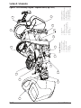
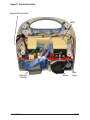
Figure 9 - Parts Assembly Diagram – Exploded view (Page 1 of 2) ................................................................. EN-29
Figure 9 - Parts Assembly Diagram (front enclosure)– Exploded view (Page 2 of 2) .......................................EN-30
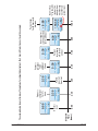
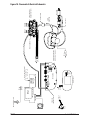
Figure 10 - Pneumatic & Electrical Schematic ....................................................................................................EN-31
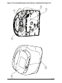
Figure 11 - Rear Enclosure View........................................................................................................................... EN-32
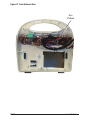
Figure 12 - Front Enclosure View ......................................................................................................................... EN-33

EN-1
Kendall SCD 700 Series
Indications
The Kendall SCD 700 sequential compression system (hereby referenced as “Kendall SCD 700 series”) is designed to
apply intermittent pneumatic compression to increase venous blood flow in at-risk patients in order to help prevent
deep vein thrombosis and pulmonary embolism. The System consists of the controller, the tubing sets (provided
with the controller) and single-patient use garments (purchased separately from this controller). The garments, both
leg sleeves and foot cuffs, compress the limbs to enhance venous blood movement. After the compression cycle has
reached set pressure, the controller measures the time it takes for the limbs to refill with blood and waits that period
of time before the next compression is initiated.
Leg Compression
The use of the Kendall SCD 700 series compression system with leg sleeves is indicated for:
1. Deep vein thrombosis and pulmonary embolism prophylaxis.
Foot Compression
The use of the Kendall SCD 700 series compression system with foot cuffs is indicated for:
1. Circulation enhancement.
2. Deep vein thrombosis prophylaxis.
3. Edema - Acute.
4. Edema - Chronic.
5. Extremity pain incident to trauma or surgery.
6. Leg Ulcers.
7. Venous stasis / venous insufficiency.
If you need further information regarding the Kendall SCD 700 series compression system or its clinical benefits,
please contact your Covidien Sales Representative.
Contraindications
Leg Compression
The Kendall SCD 700 series compression system may not be recommended for use with leg sleeve on patients with
the following:
1. Any local leg condition in which the sleeves may interfere, such as: (a) dermatitis, (b) vein ligation [immediate
postoperative], (c) gangrene, or (d) recent skin graft.
2. Severe arteriosclerosis or other ischemic vascular disease.
3. Massive edema of the legs or pulmonary edema from congestive heart failure.
4. Extreme deformity of the leg.
5. Suspected pre-existing deep venous thrombosis.
Foot Compression
The Kendall SCD 700 series compression system may not be recommended for use with foot cuffs on patients with the
following:
1. Conditions where an increase of fluid to the heart may be detrimental.
2. Congestive heart failure.
3. Pre-existing deep vein thrombosis, thrombophlebitis or pulmonary embolism.
Use with caution on the infected or insensitive extremity.

EN-2
Kendall SCD 700 Series
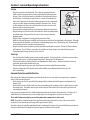
Cautions and Warnings
1. Federal (USA) law restricts this device to sale by or on the order of a physician.
2. Patients with diabetes or vascular disease require frequent skin assessment.
3. Explosion hazard. Not suitable for use in the presence of a flammable anesthetic mixture with air or with oxygen
or nitrous oxide.
4. No modification of this equipment is allowed. It is acceptable to service and repair the components identified as
serviceable in this document.
5. Although training on the use of the device is recommended, no special skills are required.
6. WARNING: Do not operate the controller if the power cord is damaged.
7. WARNING: Do not attempt to repair or replace broken tubing connectors as hazardous inflation of the sleeves
may occur.
8. WARNING: To avoid the risk of electric shock, this equipment must only be connected to supply mains with
protective earth.
9. WARNING: Do not position the controller so that it is difficult to disconnect the power cord from the AC outlet.
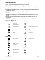
Explanation of Symbols
Caution, consult
accompanying documents.
Not made with natural rubber latex.
Consult instructions for use.
Federal (USA) law restricts this device to sale by
or on the order of a physician.
Reorder number for the device located
on the carton label.
Use by
Use By
0123
CE Mark
Device has not been subjected
to a steilization process.
Batch Code
Controller Symbols
Controller serial number
Manufacturing date code
Keep away from sunlight.
Keep dry.
Type BF protection against
electronic shock.
15%
85%
Humidity limitations
Manufacturer
-4°F
-20°C
131°F
55°C
Store between these temperatures.
WEEE (Waste from electrical
and electronic equipment)
Protection against uid ingress: spraying water
Protective earth (ground)
Protection against uid ingress: spraying water
and particulates
Equipotential ground point

EN-3
Kendall SCD 700 Series
MEDICAL EQUIPMENT 47DA
UL60601-1, ANSI/AAMI ES60601-1:2005,
CAN/CSA C22.2 NO.601.1,
CAN/CSA C22.2 NO.60101-1 (2008).
Medical- general medical equipment as to electrical shock, re and mechanical
hazards only in accordance with UL60601-1, ANSI/AAMI ES60601-1:2005,
CAN/CSA C22.2 NO.601.1, CAN/CSA C22.2 NO.60101-1 (2008).
Sterile Garment Symbols
Sterile using
ethylene oxide.
Single use device
Do not use if package is opened or damaged.
Tubing Set Symbols
Device contains phthalates.
Constructed from recyclable materials.
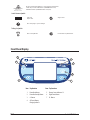
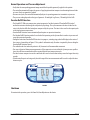
Front Panel Display
1
2
3
6
7
4
5
Item Explanation Item Explanation
1 Power On Indicator 5 Battery Status Indicators 1-3
2 Power On/Standby Button 6 Right Arrow Button
3 A - Button 7 B - Button
4 AC Power/Battery
Charging Indicator

EN-4
Kendall SCD 700 Series
Section I - General Operating Instructions
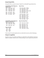
Set up
Bed
Foot
Board
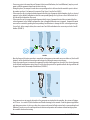
• Placethecontrolleronthefootboard.Thisisdonebygraspingthedevice
handle and the top portion of the pivoting bed hook and squeezing to open
the gap. Place it on the foot board so it straddles the foot board and release
the bed clamp. See the figure at right. Ensure its security. Alternatively, the
device can be placed on a horizontal surface appropriate for the environment,
such as on a table, within reasonable proximity to the point of use. Be sure
to allow adequate air flow to the vents located at the power cord cover and
below the tube set connection points.
• Thecontrollercanoperatewithoneortwogarmentsattachedtothepatient.
• Plugthetubingset(s)intothebackofthecontroller.Routethetubingtoward
the patient’s limbs, being careful to leave access ways clear and eliminate
tripping hazards.
• Plugthetubesintogarment(s)wrappedontothepatient’slimbs.
• Matchtheleftandrightports,markedBandArespectively,withtheleftandrightlimbsofthepatient.Although
the operation of the controller is not affected, troubleshooting can be easier. Check tubing set(s) for kinking and
secure attachment at the controller and the garment(s).
• Plugthecontrollerpowercordintoaproperlygroundedhospitalgradereceptacle.TheblueACPowerIndicator
will illuminate. If no AC Power is accessible, the controller can be run using its own internal battery power.
• Ifcompliancemonitoringisdesired,refertoSectionII.
Start-up
• PressthePowerOn/Standbybuttontobeginnormaloperation.Ifusinglegsleeves,nofurtheruserintervention
is required unless there is a fault condition detected or if therapy must be discontinued.
• Thecontrollerwillbeep,flashalltheLED’sandilluminatethedisplayscreen.Quickinternaldevicechecksare
performed, which may be audible to the user.
• ThepumpwillbegintooperateaspartoftheGarmentSelectionandVerificationprocedure.
• DetectionofinoperativeLED’s,displayscreenandtheaudibleerrorindicationfunctionatstart-upisthe
user’s responsibility.
Garment Selection and Verification
After startup, the Garment Configuration procedure allows the user to select when foot compression is required at
either of the two controller ports:
• Onthedisplay,thePortALegandPortBLegimagesblinktoindicatethedefaultgarmentconfiguration(leg
compression).
• PressingeithertheAorBButtonwillcausethecorrespondingport’slegimagetoshifttoafootimagetosignify
foot compression. The buttons must be pressed for each port that is connected to a foot cuff to turn on the cor-
responding foot image(s).
Note: Leg sleeve compression is the default configuration when the controller is first powered on. Therefore, the A
and B Button(s) do not have to be pressed to begin compression therapy when leg sleeves are being used.
The A and B buttons need to be pressed only when foot compression is to be used.
NOTE: If a garment is attached anytime after the Garment Detection procedure has started, the system must be
restarted to ensure that the proper therapy will be applied to the limb(s).
Also after startup, the controller immediately begins conducting the Garment Selection and Verification procedure at
each port to determine if the garments have been properly attached to the controller:

EN-5
Kendall SCD 700 Series
• Ifnecessary,priortothecompletionofGarmentSelectionandVerification,theAandBButton(s)maybepressed
again to shift the garment image from the foot to the leg.
• Duringthisphase,thecompressorandvalvesareoperatingandairisdeliveredoutthecontrollerportstodetect
the number and type(s) of garment(s) connected [Leg Sleeve(s) and/or Foot Cuff(s)].
• IfthecontrollersensesaproperlyattachedgarmentandthetypeofgarmentdetectedmatchestheUser-selected
garment (or the default) configuration, then the corresponding image of a Leg Sleeve or Foot Cuff for both the A
or B side will be displayed on the screen.
• IfthecontrollersensesaproperlyattachedgarmentbutthetypeofgarmentdetecteddoesnotmatchtheUser-
selected garment (or the default) configuration, then a Garment Mismatch error is triggered. Garment Mismatch
errors can be corrected by pushing the corresponding A and B buttons to change the User-selected garment type
(Leg or Foot). In the example below, the screen shows Foot Cuffs and indicates the user must press both A and B
buttons (FIGURE 1).
A B
FIGURE 1
• OncetheGarmentDetectionprocedureiscompletedandanygarmentmismatcherrorsareaddressed,theAandB
button(s) will be disabled and normal operation begins by starting the compression therapy.
• Ifonlyonecontrollerportisconnectedtoagarmentforsingle-limbcompression,thentheUser-selectedgarment
(or the default) configuration setting (Leg or Foot) for the open port will be ignored and both the leg and foot will
be grayed out such as the example shown below (FIGURE 2).
A B
FIGURE 2
• Ifanygarmentsarenotproperlydetectedorifnogarmentsareattachedtothecontroller,thesystemwilltrigger
an E12 error. See section IV (Fault Conditions and Troubleshooting) in this manual. Check the garment application
and tubing connections. In this case, either the system can be turned off and restarted or the corresponding A and
B Button(s) can be pressed to confirm problem resolution and operation will continue without having to power
the controller down and restarting.

EN-6
Kendall SCD 700 Series
Normal Operation and Pressure Adjustment
• Verifythatthecorrespondinggarmentimagesmatchthedisposablegarment(s)appliedtothepatient.
• Thecontrollerautomaticallybeginstheprocessofapplyingintermittentcompressionalternatingbetweenlimbs
or to one if only one garment is applied.
• Onsuccessivecycles,thecontrollerautomaticallyadjustsitsoperatingparameterstomaintainsetpressure.
• Thepressuresettingdependsonthetypeofgarment:45mmHgforLegSleeves;130mmHgforFootCuffs.
Vascular Refill Detection
• TheKendallSCD700seriescompressionsystemincorporatesCovidien’spatented“VascularRefillDetection”
method to customize the therapy for each patient’s physiology. This system measures the time it takes for the
veins in the limb to refill after having been compressed by the system. The time is then used in subsequent cycles
as the time between compressions.
• VascularRefillDetectionoccursautomaticallyandrequiresnooperatorinteraction.
• TheVascularRefillDetectionmethodisusedwhenfirstpoweringontheSystemafteritreachessetpressureand
every thirty minutes thereafter.
• DuringtheentiretimeVascularRefillDetectionisinprogress,arotatingringsymbolwilldisplayinthecenterof
the screen as shown below in Figure 3. This symbol is informative only. No action is required by the user dring the
Vascular Refill Detection Process.
• Themethodworksbestwhenthepatientisstill,howeveritwillaccommodatemovement.
• IfanerrorisdetectedduringanymeasurementorifthecompressionisnotwithintheSystempressurespecifica-
tions, the refill time measurement will be repeated after the next compression cycle.
• Thetimebetweencompressionsonthesamelimbwillneverbeshorterthantwentysecondsorlongerthansixty
seconds.
• Ifbothcontrollerportsarebeingused,thenthelongerofthetwomeasurementswillbeusedtoadjustthetime
between cycles.
FIGURE 3
Shutdown
To terminate the operation, press the Power On/Standby button on the device.

EN-7
Kendall SCD 700 Series
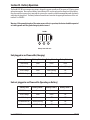
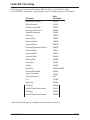
Garment Compatibility
The Kendall SCD 700 series compression system is designed for use with Kendall SCD garment Reorder Codes:
Kendall SCD Sequential Compression
Comfort Sleeves
74010 Thigh Length X-Small
74011 Thigh Length Small
74012 Thigh Length Medium
74013 Thigh Length Large
74021 Knee Length Small
74022 Knee Length Medium
74023 Knee Length Large
Express Sleeves
9529 Knee Length Medium
9530 Thigh Length Medium
9545 Thigh Length Small
9736 Thigh Length Medium (sterile)
9780 Thigh Length Large
9789 Knee Length Large
9790 Knee Length X-Large
73011 Thigh Length Small
73012 Thigh Length Medium
73013 Thigh Length Large
73022 Knee Length Medium
73023 Knee Length Large
Kendall SCD Sequential Compression
Comfort Tear-Away Sleeves
74041 Thigh Length Small
74042 Thigh Length Medium
74043 Thigh Length Large
Express Foot Cuff
5897 Regular
5898 Large
73032 Regular
73033 Large
Express Tear-Away Sleeves
9530T Thigh Length Medium
9545T Thigh Length Small
9780T Thigh Length Large
73041 Thigh Length Small
73043 Thigh Length Large
73042 Thigh Length Medium
Further instructions for garment application and use are included with the Leg Sleeve and Foot Cuff packaging.
Tubing Set Compatibility
The garments connect to the controller via the Tubing Sets provided with the controller. Additional or replacement
Tubing Sets are available as Reorder Code 9528. The Extension Tubing Sets are also available as Reorder Code 9595.

EN-8
Kendall SCD 700 Series
Section II - Compliance Meter
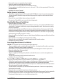
Introduction
The Kendall SCD 700 series controller has a feature called the Compliance Meter, that can be used to monitor the
amount of time a patient receives compression therapy either by shift, day or during an entire hospital stay. This
unique feature operates in the background, so that it does not interrupt daily normal operation. Prior to using the
compliance meter, confirm the controller has been set up as described in Section I.
Time is tracked using a numerator/denominator arrangement. The denominator (bottom number) is the elapsed time
since the last Compliance Meter reset or can be chosen to show a moving window of time, such as a nurse shift. The
numerator (top number) is the patient therapy time. It is the amount of time that compression therapy was applied to
the patient during the elapsed period of time specified in the denominator. The time is expressed in hours and minutes.
Any time the controller is turned off or an error condition is present, thus halting normal operation, the therapy time
(numerator) will not increment, but the elapsed time will increment. The maximum amount of time that can be
displayed is 999 hours. After the controller is off for 40 days continuously, the Compliance Meter will reset to zero.
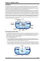
The Compliance Meter features are shown below:
Therapy time (top number)
(HHH:MM)
Elapsed time
(bottom number)
(HHH:MM)
A - button
(shift selector)
B - button
(reset button)
Right arrow
button
Shift
selections
Reset icon
FIGURE 4
Selection
Indicator
Resetting the Compliance Meter
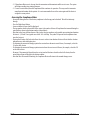
• TheComplianceMetercanbeaccessedwhenthecontrollerisonandisdeliveringtherapy.Thecontrollerwill
sound a “deny” tone, three quick beeps, at any other time such as immediately after turning the system on and
garment detection is in progress (garments blinking). Note: use of the Compliance Meter does not halt or
otherwise affect the ongoing compression therapy.
• ResettheComplianceMetertozero:
◊ Access the Compliance Meter by pressing the Right Arrow button. Pressing it again will return the user to
normal operating mode. If the Compliance Meter is accessed, but no further action is taken, then the system
will change the display back to normal operation mode in thirty seconds.
◊ Reset the Compliance Meter by pressing the B button. The confirmation screen will appear as shown in the
figure below (Figure 5). Press the A button to select check mark to confirm the reset operation. To decline the
reset, press the B button. After either A or B is pressed, the screen will revert to the Compliance Meter Screen.
FIGURE 5
Reset icon
Confirm reset
Deny reset

EN-9
Kendall SCD 700 Series
◊ If Compliance Meter reset is chosen, then the numerator and denominator will be reset to zero. The system
will begin recording time starting from zero.
◊ If a reset is not initiated, then the Compliance Meter continues its operation. This may result in inaccurate
compliance information for the patient. It is not recommended to reset the meter again until the device is
assigned to a new patient.
Accessing the Compliance Meter
• Atanytimeduringtheuseofthedevice,compliancetothetherapycanbechecked.Thiswillnotinterrupt
therapy.
• PresstheRightArrowButton.
• AscreensimilartoFigure4willbedisplayed.
• ThetopnumbershowninthemiddleofthescreenisthenumberofhoursofCompliancethatoccurredduringthe
period of time shown in the bottom number (elapsed time).
• Notethatinthelowerlefthandcornerofthescreen,therearenumbersandasymbolrepresentingtimedurations
of interest. 8, 10 and 12 are typical nurse shifts. 24 is a full day. The symbol Σ represents total compliance time
since the last reset.
• PressingtheAbutton(shiftselector)allowstheusertoselectatimedurationofinterest.Notethattheselection
indicator moves with each button press.
• Todeterminetheamountoftherapyapatienthasreceivedoverthemostrecent8hours,forexample,selectthe
‘8’ on the shift selector.
• Todeterminetheamountoftherapyapatientreceivedoverthemostrecent24hours,forexample,selectthe‘24’
on the shift selector.
• Beaware,iftheamountofelapsedtimehasnotyetreachedthetimeselectedontheshiftselector,thenthe
actual elapsed time will display in the bottom number.
• Notethatafter30secondsofinactivity,theComplianceMeterwillreturntothenormaltherapyscreen.

EN-10
Kendall SCD 700 Series
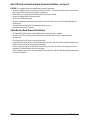
The example below shows a timeline of Compliance for a hypothetical patient. The 8 hour shift selection is active in this example:
Elapsed
Time
(hours)
0:00 2:30 3:30 6:30 7:00 8:00 18:00
0:00
0:00
2:30
2:30
2:30
3:30
5:30
6:30
5:30
7:00
6:30
8:00
8:00
8:00
16:30
18:00
Patient is
compliant
for 2
1
/2
hours
Patient is
compliant
for an
additonal
3 hours
Patient sleeps
for 10 hours with
device on.
Nurse reapplies
system to patient
for 1 more hour
Nurse selects
“Σ” on the shift
selector. This
indicates how
much therapy
since the last
system reset.
Patient
goes to 1
hour test
Patient
turns device
o for half
an hour
Device is
reset

EN-11
Kendall SCD 700 Series
Section III - Battery Operation
The Kendall SCD 700 series compression system is designed to operate normally on AC line power or DC battery power
without interruption. There are three Battery Status Indicator LED’s used to represent the charge level of the battery.
Once the controller is powered on, it may take the system a few seconds to establish communication with the battery
and display the charge level. The battery Indicator shown below is located in the upper right hand corner of the user
interface. See FIGURE 6.
Warning: If the ground integrity of the mains power cable is in question, the device should be operated
on battery power until the ground integrity can be insured.
FIGURE 6
1 32
Battery Status Indicators
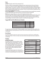
Unit plugged in and Powered On (Charging)
Battery State Battery Status 1 Battery Status 2 Battery Status 3
100% charge Green Green Green
67-99% charge Green Green Green (Pulsing)
34-66% charge Green Green (Pulsing) Off
0-33% charge Green (Pulsing) Off Off
Unit not plugged in and Powered On (Operating on Battery)
Battery State Battery Status 1 Battery Status 2 Battery Status 3
67-100% charge Green Green Green
34-66% charge Green Green Off
< 34% charge Green Off Off
15-40 minutes left* Amber (Flashing) Off Off
< 15 minutes left* Red (Flashing) Off Off

EN-12
Kendall SCD 700 Series
Unit Powered Off (charging when plugged in)
Battery State Battery Status 1 Battery Status 2 Battery Status 3
0 -100% charge Off Off Off
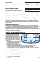
With 15-40 minutes of battery charge left, an audible error indicator will sound in a sequence of three beeps once
every two minutes. Once there is less than 15 minutes of battery charge left, the audible error indicator will sound
continuously and the dead battery icon will display as shown in FIGURE 7.
FIGURE 7
Charging the Battery
The battery will begin charging as soon as the unit is plugged into an AC power source. The amount of time required
to charge the battery will vary depending on the battery’s overall condition, age, and the controller’s state during
charging. For example, charging a new, fully drained battery will take approximately 4 hours with the controller
on standby and 8 hours with the controller powered on. The Battery Status indicators should always be used to
determine the state of charge for the battery. A fully charged battery will typically provide 6-8 hours of operation
time depending on the sleeve configuration, sleeve application, and the battery condition.
Note: If the operation time on battery power is extremely short the battery should be returned for service or
replacement.
Note: The battery performance may be reduced if it is left unused for extended periods of time. It is recommended
that the battery pack be stored with a minimum charge of 50% and kept near 25°C (77°F) if prolonged storage is
necessary.
Battery Warnings
The Kendall SCD 700 series compression system battery pack contains Lithium Ion (Li-Ion) battery cells and must be
used properly for safety and to maintain optimal performance.
• Storesparebatterypacksbetween–20°C(-4°F)and60°C(140°F).
• Donotdrop,impact,orimmerseinwater.
• Donottouchoringestanyleakingelectrolyte.Ifcontactoccurs,rinseskinand/oreyesimmediatelyandseek
medical attention if irritation develops. If ingested, contact local poison control center.
• Donotopenbattery,disposeofinfire,orshortcircuit.Doingsomaycausethebatterytoignite,explode,leak,or
become hot and cause personal injury.
• Disposeofimproperlyworkingordamagedbatterypacksaccordingtolocalregulations.
• ChargeonlywithspecifiedchargersaccordingtoCovidien’sinstructions.

EN-13
Kendall SCD 700 Series
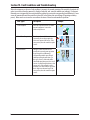
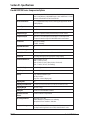
Section IV - Fault Conditions and Troubleshooting
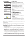
When the microprocessor detects a fault condition, it interrupts the normal operation of the controller, deactivates all
valves to vent the air from the garment(s), displays a fault code, and sounds an audible error indicator. If a Garment
Mismatch error is triggered the user may remedy the problem by pressing the corresponding A and B Button(s). Some
errors will remain active until the controller is turned off, or the battery runs out of charge (if operating on battery
power). Others can be reset once the user confirms the cause of the error and remedies the problem.
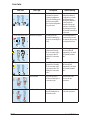
Error Types: Description Example
Service Required Error code is present because of a failed
internal component. It can not be
addressed by the user.
E5
Manual Reset Required Error that can be troubleshot and
corrected by the user but requires the
device to be powered off and on. If the
error persists, then the controller requires
service.
A B
E1
User Resettable This type of error allows the user to
remedy the issue and resume operation
by pressing the A and B button(s)
corresponding with the port affected
without powering the unit down. For
this type of error, a check mark will be
shown indicating what port is the area of
concern. A yellow triangle indicates a low
concern error. If the triangle is red it is
indicative of an error related to a pressure
that is high in an abnormal way. If the
error persists, then the controller requires
service.
A B
E2

EN-14
Kendall SCD 700 Series
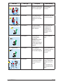
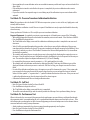
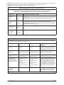
Error Codes
Error Code Error Type Description Troubleshooting
Garment Mismatch Error
User Resettable The Garment Detection
procedure has detected
a garment configuration
(Leg or Foot flashing green)
that does not match the
User-selected configuration
(Leg or Foot red).
Press the port
configuration button(s)
to turn the foot selection
on/off depending on
what type of garment(s)
is connected to the
controller. If the proper
garment is selected and
the problem persists have
the controller serviced by a
professional.
A B
System High Pressure Error
Manual Reset required System pressure has
exceeded 90 mmHg (Leg
sleeve) or 180 mmHg (Foot
Cuff).
Check for kinked tubes or
patient interference with
the garments, like pressing
foot against foot board.
A B
E1
High Pressure (Leg Sleeves)
User Resettable Leg Sleeve pressure is
greater than 47 mmHg
for10consecutivecycles;
or pressure is above 65
mmHg for 5 consecutive
cycles.
Check for a tight leg
sleeve and adjust fit
appropriately. Also check
for a partially occluded
tube.
A B
E2
High Pressure (Foot Cuffs)
User Resettable Foot Cuff pressure is
greater than 135 mmHg
for 10 consecutive cycles
or pressure is above 160
mmHg for 5 consecutive
cycles.
Check for a tight foot
cuff and adjust fit
appropriately. Also check
for a partially occluded
tube.
A B
E2
Low Pressure (Leg Sleeves)
User Resettable Leg Sleeve pressure is
less than 43 mmHg for 10
consecutive cycles.
Check for leaks in the
sleeve or the tube
connections.
Low Pressure (Foot Cuffs)
User Resettable Foot Cuff pressure is less
than 125 mmHg after 10
consecutive cycles.
Check for leaks in the cuff
or the tube connections.

EN-15
Kendall SCD 700 Series
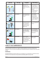
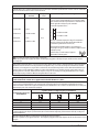
Error Code Error Type Description Troubleshooting
Low Pressure (Leg Sleeves)
User Resettable Leg Sleeve pressure is not
between 35 and 55 mmHg
for 12 consecutive cycles.
Check for leaks in the
sleeve or the tube
connections.
Low Pressure (Foot Cuffs)
User Resettable Foot Cuff pressure is not
between 110 and 150
mmHg for 12 consecutive
cycles.
Check for leaks in the cuff
or the tube connections.
E4
Valve Feedback Error
Service Required If a valve electrically
malfunctions, this error
will be displayed.
Service Technician only:
Verify that the valve
assembly wires are
properly connected
and confirm solenoid
actuation.
E5
Software Error
Service Required Upon startup, and
periodically during
operation the
microprocessor performs
diagnostic tests. If a
software error is detected,
this Error Indicator will be
triggered.
Return to Covidien for
service.
E6
Compressor Error
Service Required If the compressor
electrically malfunctions
this error will be displayed.
Service Technician only:
Verify that the compressor
wires are properly
connected.
E7
Vent Error
User Resettable The pressure in a garment
is greater than 20 mmHg
at the end of any vent
period.
Check tubing for kink or
occlusion. Check garment
application (too loose or
tight).
Service Technician only:
Check for kinked internal
tubing.
A B
E8

EN-16
Kendall SCD 700 Series
Error Code Error Type Description Troubleshooting
Temperature Error
Manual reset required If the internal case
temperature of the
controller drops below
5°C (41°F) or exceeds 55°C
(131°F).
High temperature: Make
sure the controller is not
covered by bedding and
that the fan port, located
near the power cord is not
obstructed.
Low Temperature: Allow
the system to warm to
room temperature.
E9
E9
Battery Error
Service Required Safe battery operation of
the controller can not be
ensured.
Service Technician
Only: Ensure that an
unauthorized battery
pack replacement has not
been made. Replace pack
or return to Covidien for
service.
E10
Tubing Disconnect Error
User Resettable Pressure measured in
the inflatable garment is
below 10 mmHg for 10
consecutive cycles or no
garments are detected
during startup.
Check for disconnected
tube sets or garments and
reconnect.
A B
E12
Pressure Transducer Error
Service Required The system could not sense
a pressure rise of more
than 5 mmHg during an
inflation cycle or during
start up.
Service Technician Only:
Check the transducer tube
inside the controller and
ensure it is neither kinked
or disconnected.
E13
Low Battery Error
Recharge Battery There is less than 15
minutes of battery charge
remaining. The pump and
valves will continue to
operate for as long as there
is enough power.
Plug the controller into an
AC power outlet.
Section V - Service and Maintenance
This service manual is intended for use as a guide to technically qualified personnel when evaluating System
malfunctions. It is not to be construed as authorization to perform warranty repairs. Unauthorized service will void the
warranty.
Introduction
The Kendall SCD 700 series controller contains no user serviceable parts. User maintenance is covered in the sections
that follow. All other maintenance must be performed by technically qualified service personnel.

EN-17
Kendall SCD 700 Series
Service technicians should be familiar with the operator’s portion of this manual and the operating principles of the
Kendall SCD 700 series compression system. If a controller is to be returned to Covidien for service, a description of
the operating conditions and the fault code displayed should accompany the unit. The fault codes displayed by the
controller are useful in diagnosing service problems.
This manual describes service procedures to the circuit board level, with an exploded view of the controller shown
in Figure 9. If a component failure on a circuit board is suspected, the unit should be returned for service. It is
recommended that the system be returned with the circuit board in place, as removal of the board(s) involves
additional risk of mechanical damage and damage from electrostatic discharge (ESD).
Warranty and Factory Service
Covidien warrants that your Kendall SCD 700 series compression system is free from defective material and
workmanship. Our obligation under this warranty is limited to the repair of controllers returned to a service center,
transportation charges prepaid, within one year of delivery to the original purchaser. Specifically, we agree to
service and/or adjust any controller as required if returned for that purpose, and to replace and repair any part
which, upon our examination, is proven to have been defective. This warranty does not apply to the Tubing Set or
the disposable garments, or to equipment damaged through shipping, tampering, negligence, or misuse, including
liquid immersion, autoclaving, ETO sterilization, or the use of unapproved cleaning solutions. To the extent permitted
by applicable law, this limited warranty does not cover, and is intended to exclude, any and all liability on the part of
the Company, whether under this limited warranty or any warranty implied by law, for any indirect or consequential
damages for breach hereof or thereof. Except as expressly provided above in the limited warranty, to the extent
permitted by applicable law, the Company hereby negates and disclaims all express and to the extent permitted by
applicable law, implied warranties, including the warranties or merchantability and fitness for a particular purpose.
controllers requiring repairs should be sent to a service center. Call one of the service centers listed. Obtain a return
material authorization number and ship the controller, prepaid and insured in the original carton.
CANADA
Covidien Canada
7300 Trans Canada Highway
Pointe-Claire,QcH9R1C7
877-664-8926
UNITED STATES
Covidien
5920 Longbow Drive
Boulder CO 80301
1- (800) 962-9888
OUTSIDE U.S. AND CANADA
Covidien
Service Centre
Unit 2 Talisman Business Centre
London Road
Bicester, England OX26 6HR
(+44)1869328065
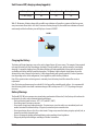
Disposal:
If the controller, tubing assembly and/or garment(s) is to be disposed of, follow the local country regulations
taking environmental factors into consideration.
Service Precautions:
• AlwaysunplugthecontrollerfromMainsvoltagebeforeservicingthecontroller.
• Usepropertechniquessuchasgroundingstrapsandpadstoprotectprintedcircuitboardassembliesfrom
ESD (Electrostatic Discharge).
Fan Filter, Exhaust Filter and Ventilation
CAUTION: Unplug the controller before accessing the fan filter or exhaust filter.
The fan filter and exhaust filter must be kept clean to ensure continued trouble-free operation. The controller
should never be run without the fan filter and exhaust filter in place. Clean or replace the filter when required. See
instructions in the General Disassembly/Reassembly Section.
During system use, obstruction of the fan cover and vents should be avoided. Free flow of air is necessary to prevent
overheating and premature component failure.
La pagina si sta caricando...
La pagina si sta caricando...
La pagina si sta caricando...
La pagina si sta caricando...
La pagina si sta caricando...
La pagina si sta caricando...
La pagina si sta caricando...
La pagina si sta caricando...
La pagina si sta caricando...
La pagina si sta caricando...
La pagina si sta caricando...
La pagina si sta caricando...
La pagina si sta caricando...
La pagina si sta caricando...
La pagina si sta caricando...
La pagina si sta caricando...
La pagina si sta caricando...
La pagina si sta caricando...
-
 1
1
-
 2
2
-
 3
3
-
 4
4
-
 5
5
-
 6
6
-
 7
7
-
 8
8
-
 9
9
-
 10
10
-
 11
11
-
 12
12
-
 13
13
-
 14
14
-
 15
15
-
 16
16
-
 17
17
-
 18
18
-
 19
19
-
 20
20
-
 21
21
-
 22
22
-
 23
23
-
 24
24
-
 25
25
-
 26
26
-
 27
27
-
 28
28
-
 29
29
-
 30
30
-
 31
31
-
 32
32
-
 33
33
-
 34
34
-
 35
35
-
 36
36
-
 37
37
-
 38
38


Covidien Kendall SCD 700 Series Operation And Service Manual
- Tipo
- Operation And Service Manual
in altre lingue
- English: Covidien Kendall SCD 700 Series
Altri documenti
-
LG 27HJ713SW Guida Rapida
-
Apex Digital Sedens 500 Manuale utente
-
Gima QV-500 Manuale utente
-
Therabody PROBDL-MP2-PKG-US Guida utente
-
 Pressalit R8582318299 Guida utente
-
BD ClipVac 5506E Instructions For Use Manual
-
Therabody B09QTQDY3B Manuale utente
-
Abbott Tendyne TENDV-SP-33A Instructions For Use Manual
-
Drive Vacu-Aide 7310 Series Manuale del proprietario
-
Verbatim 44071 Scheda dati
