Hitachi HRNM/FSN(2)(M)(E) Istruzioni per l'uso
- Categoria
- Condizionatori d'aria a sistema split
- Tipo
- Istruzioni per l'uso

Read and understand this manual before using this air conditioner. Keep this manual for future reference.
Lea atentamente el presente manual antes de utilizar el sistema de aire acondicionado. Guárdelo para futuras consultas.
Lesen Sie dieses Handbuch gründlich durch, bevor Sie diese Klimaanlage benutzen. Benutzen Sie dieses Handbuch
für eventuell auftretende Fragen oder Probleme.
Lisez ce manuel jusqu'à totale compréhension avant d'installer cet appareil de climatisation. Conservez ce manuel afin
de vous y référer ultérieurement.
Leggere e comprendere il presente manuale prima di utilizzare il condizionatore d'aria. Conservare il presente manuale
per la consultazione futura.
Leia e compreenda este manual antes de utilizar este ar condicionado. Guarde este manual para referência futura.
Læs denne vejledning grundigt, inden du tager klimaanlægget i brug. Gem vejledningen til fremtidige opslag.
Lees deze handleiding goed door voordat u de airconditioner gebruikt. Bewaar de handleiding voor later gebruik.
Läs denna handbok noga innan luftkonditioneringsaggregatet används. Spara handboken för framtida bruk.
.Διαβάστε προσεκτικά αυτό το εγχειρίδιο πριν τη χρή ση του κλιματιστικού. Κρατήστε το εγχειρίδιο για μελλοντική αναφορά
INSTALLATION AND OPERATION MANUAL
MANUAL DE INSTALACIÓN Y FUNCIONAMIENTO
INSTALLATIONS- UND BETRIEBSHANDBUCH
MANUEL D’INSTALLATION ET DE FUNCTIONNEMENT
MANUALE D’INSTALLAZIONE E D’USO
ENGLISHESPAÑOL
DEUTSCHFRANÇAISITALIANO
PORTUGUÊS
DANSK
NEDERLANDS
SVENSKA
MANUAL DE INSTALAÇÄO E DE FUNCIONAMENTO
BRUGER- OG MONTERINGSVEJLEDNING
INSTALLATIE- EN BEDIENINGSHANDLEIDING
HANDBOK FÖR INSTALLATION OCH ANVÄNDING
ΕΓΧΕΙΡΙΔΙΟΕΓΚΑΤΑΣΤΑΣΗΣΚΑΙΛΕΙΤΟΥΡΓΙΑΣ
DC INVERTER HRNM/FSN(2)(M)(E)
ΕΛΛΗΝΙΚΑ


Specications in this manual are subject to change without notice in order that HITACHI
may bring the latest innovations to their customers.
Whilst every effort is made to ensure that all specications are correct, printing errors are
beyond Hitachi’s control; Hitachi cannot be held responsible for these errors.

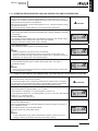
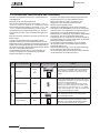
DANGER – Immediate hazard which WILL result in severe injury or death.
PELIGRO – Riesgos inmediatos que PRODUCIRÁN lesiones personales graves e incluso la muerte.
GEFAHR – Unmittelbare Gefahrenquellen, die zu schweren Verletzungen oder zum Tod führen.
DANGER – Dangers instantanés de blessures corporelles sévères ou de mort.
PERICOLO – Pericolo immediato che PRODURRÀ ferite gravi o la morte.
PERIGO – Problemas imediatos que IRÃO resultar em graves ferimentos pessoais ou morte.
FARE – Overhængende fare, som VIL resultere i alvorlig personskade eller dødsfald.
GEVAAR – Onmiddellijke risico’s die ernstige persoonlijke verwondingen of de dood ten gevolge kunnen hebben.
FARA – Omedelbar risk som medför svår personskada eller död.
KINAYNO – Άµεσος κίνδυνος που ΘΑ έχει ως αποτέλεσµα σοβαρές σωµατικές βλάβες ή θάνατο.
WARNING – Hazards or unsafe practices which COULD result in severe personal injuries or death.
AVISO – Riesgos o prácticas poco seguras que PODRÍAN producir lesiones personales e incluso la muerte.
WARNUNG –
Gefährliche oder unsichere Anwendung, die zu schweren Körperverletzungen oder zum Tod führen kann.
ATTENTION – Utilisation dangereuse ou sans garantie de sécurité qui PEUT provoquer de sévères blessures
personnelles ou la mort.
AVVISO – Pericoli o azioni pericolose che POTREBBERO avere come esito lesioni siche gravi o il decesso.
AVISO – Riesgos o prácticas poco seguras que PUEDEN producir lesiones personales e incluso la muerte
ADVARSEL – Farer eller farlig brug, som KAN resultere i alvorlig personskade eller dødsfald.
WAARSCHUWING – Gevaren of onveilige praktijken die ernstig persoonlijk letsel of de dood tot
gevolg KUNNEN hebben.
VARNING – Risker eller osäkra tillvägagångssätt som KAN leda till svåra personskador eller dödsfall.
– Κίνδυνοι ή επικίνδυνες πρακτικές, οι οποίες ΜΠΟΡΕΙ να έχουν ως αποτέλεσµα σοβαρές
σωµατικές βλάβες ή θάνατο.
CAUTION –
Hazards or unsafe practices which COULD result in minor personal injury or product or property damage.
PRECAUCIÓN – Riesgos o prácticas poco seguras que PODRÍAN provocar lesiones personales de menor
importancia o daños en el producto u otros bienes.
VORSICHT – Gefährliche oder unsichere Anwendung, die geringfügigen Personen-, Produkt- oder Sachschaden
verursachen kann.
PRECAUTION – Utilisation dangereuse ou sans garantie de sécurité qui PEUT provoquer des blessures mineures ou
des dommages au produit ou aux biens.
ATTENZIONE – Pericoli o azioni pericolose che POTREBBERO avere come esito lesioni siche minori o danni al
prodotto o ad altri beni.
CUIDADO – Perigos e procedimentos perigosos que PODERÃO PROVOCAR danos pessoais ligeiros ou danos em
produtos e bens.
FORSIGTIG – Farer eller farlig brug, som KAN resultere i mindre skade på personer, produkt eller ejendom.
LET OP – Gevaren of onveilige praktijken die licht persoonlijk letsel of beschadiging van het product
of eigendommen tot gevolg KUNNEN hebben.
VARSAMHET – Risker eller farliga tillvägagångssätt som KAN leda till mindre personskador eller skador på
produkten eller på egendom.
– Κίνδυνοι ή επικίνδυνες πρακτικές, οι οποίες ΜΠΟΡΕΙ να έχουν ως αποτέλεσµα την πρόκληση ελαφρών
σωµατικών βλαβών ή καταστροφή περιουσίας.

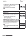
ATTENTION:
This product shall not be mixed with general house waste at the end of its life and it shall be retired according to the
appropriated local or national regulations in a environmentally correct way.
Due to the refrigerant, oil and other components contained in Air Conditioner, its dismantling must be done by a
professional installer according to the applicable regulations.
Contact to the corresponding authorities for more information.
ATENCIÓN:
Éste producto no se debe eliminar con la basura doméstica al nal de su vida útil y se debe desechar de manera
respetuosa con el medio ambiente de acuerdo con los reglamentos locales o nacionales aplicables.
Debido al refrigerante, el aceite y otros componentes contenidos en el sistema de aire acondicionado, su desmontaje
debe realizarlo un instalador profesional de acuerdo con la normativa aplicable.
Para obtener más información, póngase en contacto con las autoridades competentes.
ACHTUNG:
Dass Ihr Produkt am Ende seiner Betriebsdauer nicht in den allgemeinen Hausmüll geworfen werden darf, sondern
entsprechend den geltenden örtlichen und nationalen Bestimmungen auf umweltfreundliche Weise entsorgt werden
muss.
Aufgrund des Kältemittels, des Öls und anderer in der Klimaanlage enthaltener Komponenten muss die Demontage von
einem Fachmann entsprechend den geltenden Vorschriften durchgeführt werden.
Für weitere Informationen setzen Sie sich bitte mit den entsprechenden Behörden in Verbindung.
ATTENTION:
Ne doit pas être mélangé aux ordures ménagères ordinaires à la n de sa vie utile et qu’il doit être éliminé
conformément à la réglementation locale ou nationale, dans le plus strict respect de l’environnement.
En raison du frigorigène, de l’huile et des autres composants que le climatiseur contient, son démontage doit être
réalisé par un installateur professionnel conformément aux réglementations en vigueur.
ATTENZIONE:
I
ndicazioni per il corretto smaltimento del prodotto ai sensi della Direttiva Europea 2002/96/EC e Dlgs 25 luglio 2005 n.151
Il simbolo del cassonetto barrato riportato sull’ apparecchiatura indica che il prodotto alla ne della propria vita utile
deve essere raccolto separatamente dagli altri riuti.
L’utente dovrà, pertanto, conferire l’apparecchiatura giunta a ne vita agli idonei centri di raccolta differenziata dei riuti
elettronici ed elettrotecnici, oppure riconsegnarla al rivenditore al momento dell’ acquisto di una nuova apparecchiatura
di tipo equivalente.
L’adeguata raccolta differenziata delle apparecchiature dismesse, per il loro avvio al riciclaggio, al trattamento ed allo
smaltimento ambientalmente compatibile, contribuisce ad evitare possibili effetti negativi sull’ ambiente e sulla salute e
favorisce il riciclo dei materiali di cui è composta l’ apparecchiatura.
Non tentate di smontare il sistema o l’unità da soli poichè ciò potrebbe causare effetti dannosi sulla vostra salute o sull’
ambiente.
Vogliate contattare l’ installatore, il rivenditore, o le autorità locali per ulteriori informazioni.
Lo smaltimento abusivo del prodotto da parte dell’utente può comportare l’applicazione delle sanzioni amministrative di
cui all’articolo 50 e seguenti del D.Lgs. n. 22/1997.
ATENÇÃO:
O seu produto não deve ser misturado com os desperdícios domésticos de carácter geral no nal da sua duração e
que deve ser eliminado de acordo com os regulamentos locais ou nacionais adequados de uma forma correcta para o
meio ambiente.
Devido ao refrigerante, ao óleo e a outros componentes contidos no Ar condicionado, a desmontagem deve ser
realizada por um instalador prossional de acordo com os regulamentos aplicáveis.
Contacte as autoridades correspondentes para obter mais informações.
BEMÆRK:
At produktet ikke må smides ud sammen med almindeligt husholdningsaffald, men skal bortskaffes i overensstemmelse
med de gældende lokale eller nationale regler på en miljømæssig korrekt måde.
Da klimaanlægget indeholder kølemiddel, olie samt andre komponenter, skal afmontering foretages af en fagmand i
overensstemmelse med de gældende bestemmelser.
Kontakt de pågældende myndigheder for at få yderligere oplysninger.
ATTENTIE:
Dit houdt in dat uw product niet wordt gemengd met gewoon huisvuil wanneer u het weg doet en dat het wordt
gescheiden op een milieuvriendelijke manier volgens de geldige plaatselijke en landelijke reguleringen.
Vanwege het koelmiddel, de olie en andere onderdelen in de airconditioner moet het apparaat volgens de geldige
regulering door een professionele installateur uit elkaar gehaald worden.
Neem contact op met de betreffende overheidsdienst voor meer informatie.
OBS!:
Det innebär att produkten inte ska slängas tillsammans med vanligt hushållsavfall utan kasseras på ett miljövänligt sätt i
enlighet med gällande lokal eller nationell lagstiftning.
Luftkonditioneringsaggregatet innehåller kylmedium, olja och andra komponenter, vilket gör att det måste demonteras
av en fackman i enlighet med tillämpliga regelverk.
Ta kontakt med ansvarig myndighet om du vill ha mer information.
ΠΡΟΣΟΧΗ:
Σημαίνει ότι το προϊόν δεν θα πρέπει να αναμιχθεί με τα διάφορα οικιακά απορρίμματα στο τέλος του κύκλου ζωής του
και θα πρέπει να αποσυρθεί σύμφωνα με τους κατάλληλους τοπικούς ή εθνικούς κανονισμούς και με τρόπο φιλικό προς
το περιβάλλον.
Λόγω του ψυκτικού, του λαδιού και άλλων στοιχείων που περιέχονται στο κλιματιστικό, η αποσυναρμολόγησή του πρέπει
να γίνει από επαγγελματία τεχνικό και σύμφωνα με τους ισχύοντες κανονισμούς.
Για περισσότερες λεπτομέρειες, επικοινωνήστε με τις αντίστοιχες αρχές.


English
From 4th July 2007 and following Regulation EC Nº 842/2006 on Certain Fluorinated Greenhouse gases, it is mandatory to ll in the
label attached to the unit with the total amount of refrigerant charged on the installation.
Do not vent R410A/R407C into the atmosphere: R410A & R407C are uorinated greenhouse gases covered by the Kyoto protocol
global warming potential (GWP) R410A/R407C: = 1975/1652.5.
Español
Desde el 4 de Julio de 2007 y en base al Reglamento CE Nº 842/2006 sobre determinados gases uorados de efecto invernadero, es
obligatorio rellenar la etiqueta suministrada con la unidad con la cantidad total de refrigerante con que se ha cargado la instalación.
No descargue el R410A/R407C en la atmósfera: R410A y R407C son gases uorados cubiertos por el protocolo de Kyoto con un
potencial de calentamiento global (GWP): = 1975/1652.5.
Deutsch
Ab 4. Juli 2007 und folgende Verordnung EG Nr. 842/2006 Bestimmte uorierte Treibhausgase, auf dem Schild, das sich am Gerät
be ndet, muss die Gesamtkältemittelmenge verzeichnet sein, die bei der Installation eingefüll wird.
Lassen sie R410A/R407C nicht in die luft entweichen: R410A & R407C sind uorierte treibhausgase, die durch das Kyoto-protokoll
erfasst sind. Sie besitzen folgendes treibhauspotential (GWP) R410A/R407C: = 1975/1652.5.
France:
Du 4 Juillet 2007 et en fonction de la Réglementation CE Nº 842/2006 concernant certains gaz à effet de serre uorés, il est obligatoire
de remplir l'étiquette attachée à l'unité en indiquant la quantité de uide frigorigène qui a été chargée à l'installation.
Ne laissez pas le R410A/R407C se répandre dans l'atmosphère: le R410A et le R407C sont des gaz à effet de serre uorés, couverts
par le protocole de Kyoto avec un potentiel de rechauffement global (PRG) R410A/R407C: = 1975/1652.5.
Italiano
Dal 4 Luglio 2007 e in base alla Normativa EC Nº 842/2006 su determinati gas uorurati ad effetto serra, è obbligatorio compilare
l'etichetta che si trova sull'unità inserendo la quantità totale di refrigerante caricato nell'installazione.
Non scaricare R410A/R407C nell'atmosfera: R410A e R407C sono gas uorurati ad effetto serra che in base al protocollo di Kyoto
presentano un potenziale riscaldamento globale (GWP) R410A/R407C: = 1975/1652.5.
Português
A partir de 4 de Julho de 2007 e em conformidade com a Regulamentação da UE Nº 842/2006 sobre determinados gases uorados
com efeito de estufa, é obrigatório preencher a etiqueta a xada na unidade com a quantidade total de refrigerante carregada na
instalação.
Não ventilar R410A/R407C para a atmosfera: o R410A e o R407C são gases uorados com efeito de estufa abrangidos pelo potencial
de aquecimiento global (GWP) do protocolo de Quioto: = 1975/1652.5.
Dansk
Fra d. 4. Juli 2007 og i henhold til Rådets forordning (EF) nr. 842/2006 om visse uorholdige drivhusgasser, skal installationens samlede
mængde kølevæske fremgå at den etiket, der er klæbet fast på enheden.
Slip ikke R410A/R407C ud i atmosfæren: R410 & R407C er uorholdige drivhus-gasser, der er omfattet af Kyoto-protokollens globale
opvarmningspotentiale (GWP) R410A/R407C: = 1975/1652.5.
Nederlands
Vanaf 4 Juli 2007 en conform richtlijn EC Nº 842/2006 voor bepaalde uorbroeikasgassen, dient u de tabel in te vullen op de unit met
het totale koelmiddelvolume in de installatie.
Laat geen R410A/R407C ontsnappen in de atmosfeer: R410A & R407C zijn uorbroeikasgassen die vallen onder het protocol van
Kyoto inzake klimaatverandering global warming potential (GWP) R410A/R407C: = 1975/1652.5.
Svenska
Från och med 4 Juli 2007 och enligt reglering EC Nº 842/2006 om vissa uorhaltiga växthusgaser, måste etiketten som sitter på
enheten fyllas i med sammanlagd mängd kylmedium som fyllts på under installationen.
Släpp inte ur R410A/R407C i atmosfären: R410A & R407C är uorhaltiga växthus-gaser som omfattas av Kyotoprotokollet om global
uppvärmnings-potential (GWP) R410/R407C: = 1975/1652.5.
Eλλhnika
Από τις 4 Ιουλίου 2007 και σύμφωνα με τον Κανονισμό 842/2006/ΕΚ για για ορισμένα φθοριούχα αέρια θερμοκηπίου, είναι υποχρεωτική
η συμπλήρωση της επισήμανσης που επισυνάπτεται στη μονάδα με το συνολικό ποσό ψυκτικού που εισήχθη κατά την εγκατάσταση.
Μην απελευθερωνετε R410A/R407C στην ατμοσφαιρα τα R410A & R407C ειναι φθοριουχα αερια του θερμοκηπιου που εμπιπτουν στο
πρωτοκολλο του κυοτο δυναμικο θερμανσησ του πλανητη (GWP) R410A/R407C: = 1975/1652.5

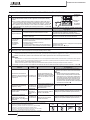
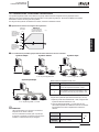
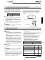
English
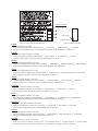
Instructions to ll in the "F-Gas Label":
1.- Fill in the Label with indelible ink the refrigerant amounts:
O
- Factory Charge,
P
- Additional Charge &
Q
- Total Charge.
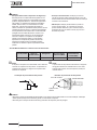
2.- Stick the Protection Plastic Film on the F-Gas Label (delivered in a plastic bag with the Manual). To see Figure nº 2.
Español
Instrucciones para rellenar la etiqueta "F-Gas Label":
1.- Anote las cantidades en la etiqueta con tinta indeleble:
O
- Carga de Fábrica,
P
- Carga Adicional y
Q
- Carga Total.
2.- Coloque el adhesivo plástico de protección (entregado adjunto al Manual). Ver Figura nº 2.
Deutsch
Anleitung zum Ausfüllen des Etiketts "F-Gas Label":
1.- Schreiben Sie die Mengen mit wischfester Tinte auf das Etikett:
O
- Werksbefüllung,
P
- Zusätzliche Befüllung &
Q
- Gesamtfüllmenge.
2.- Bringen Sie den Schutzaufkleb an (zusammen mit dem Handbuch geliefert). Siehe Abbildung Nr. 2.
France:
Instructions pour remplir l'Étiquette "F-Gas Label":
1.- Annotez les quantités sur l'Étiquette avec de l'encre indélébile:
O
- Charge en usine,
P
- Charge supplémentaire et
Q
- Charge totale.
2.- Placez le plastique autocollant de protection (remis avec le Manual). Voir Figure nº 2.
Italiano
Istruzioni per compilare l'Etichetta "F-Gas Label":
1.- Annotare le quantità sull'etichetta con inchiostro indelebile:
O
- Quantità già caricata,
P
- Carica aggiuntiva e
Q
- Carica totale.
2.- Collocare l'adesivo plastico di protezione (consegnato assieme al Manuale). Vedere Figura n. 2.
Português
Instruções para preencher a etiqueta "F-Gas Label":
1.- Anote as quantidades na etiqueta com tinta indelével:
O
- Carga de fábrica,
P
- Carga adicional e
Q
- Carga total.
2.- Coloque o adesivo plástico de protecção (fornecido com o Manual). Ver Figura nº 2.
Dansk
Instruktioner til udfyldning af etiketten "F-Gas Label":
1.- Angiv mængderne på etiketten med uudsletteligt blæk:
O
- Fabrikspåfyldning,
P
- Ekstrapåfyldning &
Q
- Samletpåfyldning.
2.- Sæt det beskyttende klæbemærke (der leveres sammen med brugervejledningen) på. Se g. 2.
Nederlands
Instructies voor het invullen van het label "F-Gas Label":
1.- Noteer de hoeveelheden met onuitwisbare inkt op het label:
O
- Fabrieksvulling,
P
- Extra vulling &
Q
- Totale vulling.
2.- Plaats de plastic beschermband (met de handleiding meegeleverd). Zie Figuur nr. 2.
Svenska
Instruktioner för påfyllning, etiketten "F-Gas Label":
1.- Anteckna kvantiteterna på etiketten med permanent bläck:
O
- Fabrikspåfyllning,
P
- Ytterligare påfyllning &
Q
- Total påfyllning.
2.- Klistra på skydds lmen i plast ( nns i pärmen till handboken). Se bild nr. 2.
Eλλhnika
Τρόπος συμπλήρωσης της ετικέτας "F-Gas Label":
1.- Σημειώστε στην ετικέτα τις ποσότητες με ανεξίτηλο μελάνι:
O
- Εργοστασιακή πλήρωση,
P
- Πρόσθετη πλήρωση &
Q
- Συνολική πλήρωση.
2.- Τοποθετήστε το πλαστικό, προστατευτικό αυτοκόλλητο (που έχει παραδοθεί με το Εγχειρίδιο). Ανατρέξτε στην εικόνα 2
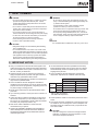
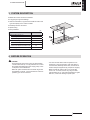
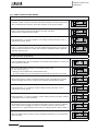
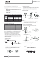
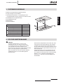
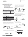
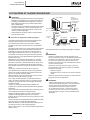
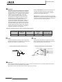
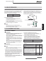
Figure 1. F-Gas Label with Protection Plastic Film Figure 2. Protection Plastic Film
Protection Plastic Film
Adhesive Surface
Peel-off Paper

PART I OPERATION
1. SAFETY SUMMARY
2. IMPORTANT NOTICE
3. SYSTEM DESCRIPTION
4. BEFORE OPERATION
5. REMOTE CONTROLLER OPERATION
6. AUTOMATIC CONTROLS
7. BASIC TROUBLESHOOTING
PART II INSTALLATION
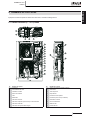
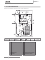
8. NAME OF PARTS
9. REFRIGERANT CYCLE
10. TRANSPORTATION AND HANDLING
11. UNITS INSTALLATION
12. PIPING AND REFRIGERANT CHARGE
13. ADDITIONAL REFRIGERANT CHARGE
14. DRAIN PIPING
15. ELECTRICAL WIRING
16. INSTALLATION OF REMOTE CONTROLLER
17. TEST RUNNING
18. SAFETY SUMMARY & CONTROL DEVICE SETTING
19. TROUBLESHOOTING
1ª PARTE: FUNCIONAMIENTO
1. RESUMEN DE SEGURIDAD
2. AVISO IMPORTANTE
3. DESCRIPCIÓN DEL SISTEMA
4. ANTES DEL FUNCIONAMIENTO
5. FUNCIONAMIENTO DEL MANDO A DISTANCIA
6. CONTROLES AUTOMÁTICOS
7. RESOLUCIÓN DE PROBLEMAS BÁSICOS
2ª PARTE: INSTALACIÓN
8. NOMBRE DE LAS PIEZAS
9. CICLO DE REFRIGERANTE
10. INSTALACIÓN DE LAS UNIDADES
11. TUBERÍA Y CARGA DE REFRIGERANTE
12. TUBERÍA DE DESAGÜE
13. CARGA ADICIONAL DE REFRIGERANTE
14. TUBERIA DE DESAGÜE
15. CABLEADO ELÉCTRICO
16. INSTALACIÓN DEL MANDO A DISTANCIA
17. PRUEBA DE FUNCIONAMIENTO
18. RESUMEN DE SEGURIDAD Y AJUSTE DE LOS
DISPOSITIVOS DE CONTROL
19. RESOLUCIÓN DE PROBLEMAS
TEIL I – BETRIEB
1. SICHERHEITSÜBERSICHT
2. WICHTIGER HINWEIS
3. SYSTEMBESCHREIBUNG
4. VOR DER INBETRIEBNAHME
5. BETRIEB MIT FERNBEDIENUNG
6. AUTOMATISCHE STEUERUNG
7. GRUNDLEGENDE FEHLERBESEITIGUNG
TEIL II – INSTALLATION
8. TEILEBEZEICHNUNG
9. KÜHLKREISLAUF
10. TRANSPORT UND BEDIENUNG
11. GERÄTE INSTALLATION
12. ROHRLEITUNGEN UND KÄLTEMITTELMENGE
13. ZUSÄTZLICHE KÄLTEMITTELMENGE
14. ABFLUSSLEITUNGEN
15. VERKABELUNG
16. INSTALLATION EINER FERNBEDIENUNG
17. TESTLAUF
18. SICHERHEITSÜBERSICHT UND EINSTELLUNG DER
STEUERGERÄTE
19. FEHLERBEHEBUNG
PARTIE I – FONCTIONNEMENT
1. CONSIGNES DE SÉCURITÉ
2. REMARQUES IMPORTANTES
3. DESCRIPTION DU SYSTÈME
4. AVANT L’UTILISATION
5.
FONCTIONNEMENT DE L’INTERRUPTEUR À DISTANCE
6. CONTRÔLES AUTOMATIQUES
7. DÉPANNAGE DE BASE
PARTIE II – INSTALLATION
8. NOMENCLATURE DES PIÈCES
9. CYCLE FRIGORIFIQUE
10. TRANSPORT ET MANIPULATION
11. INSTALLATION DES UNITÉS
12. TUYAUTERIE ET CHARGE FRIGORIFIQUE
13. CHARGE FRIGORIGÈNE SUPPLÉMENTAIRE
14. TUYAUTERIE D’ÉVACUATION DES CONDENSATS
15. CÂBLAGE ÉLECTRIQUE
16. INSTALLATION DE LA TÉLÉCOMMANDE
17. TEST DE FONCTIONEMENT
18. SOMMAIRE DES DISPOSITIFS DE SÉCURITÉ &
RÉGLAGE DES ORGANES DE CONTRÔLE
17. DEPANNAGE
PARTE I FUNZIONAMENTO
1. PRECAUZIONI PER LA SICUREZZA
2. NOTA IMPORTANTE
3. DESCRIZIONE DEL SISTEMA
4. PROCEDURA PRELIMINARE
5. FUNZIONAMENTO DEL DISPOSITIVO DI CONTROLLO
REMOTO
6. CONTROLLI AUTOMATICI
7. RISOLUZIONE DEI PROBLEMI MINORI
PART II INSTALLAZIONE
8. ELENCO DEI COMPONENTI
9. CICLO REFRIGERANTE
10. TRASPORTO E MOVIMENTAZIONE
11. INSTALLAZIONE DELLE UNITÀ
12. LINEA E CARICA DI REFRIGERANTE
13. CARICA DI REFRIGERANTE AGGIUNTIVA
14. LINEA DI DRENAGGIO
15. COLLEGAMENTI ELETTRICI
16. INSTALLAZIONE DEL COMANDO REMOTO
17. FUNZIONAMENTO DI PROVA
18. RIEPILOGO DELLE IMPOSTAZIONI DEI DISPOSITIVI DI
CONTROLLO E SICUREZZA
19. RISOLUZIONE DEI PROBLEMI
PARTE I FUNCIONAMENTO
1. RESUMO DA SEGURANÇA
2. NOTA IMPORTANTE
3. DESCRIÇÃO DO SISTEMA
4. ANTES DE ARRANCAR A UNIDADE
5. FUNCIONAMENTO DO CONTROLO REMOTO
6. CONTROLOS AUTOMÁTICOS
7. RESOLUÇÃO DE PROBLEMAS BÁSICOS
PARTE II INSTALAÇÃO
8. NOME DAS PEÇAS
9. CICLO DE REFRIGERAÇÃO
10. TRANSPORTE E MANUSEAMENTO
11. INSTALAÇÃO DAS UNIDADES
12. TUBAGEM E CARGA DE REFRIGERANTE
13. CARGA ADICIONAL DE REFRIGERANTE
14. TUBAGEM DE ESGOTO
15. LIGAÇÕES ELÉCTRICAS
16. INSTALAÇÃO DO CONTROLO REMOTO
17. PROVA DE FUNCIONAMENTO
18. SUMÁRIO DE SEGURANÇA E AJUSTE DE
DISPOSITIVO DE CONTROLO
19. RESOLUÇÃO DE PROBLEMAS

DEL I - BETJENING
1. OVERSIGT OVER SIKKERHED
2. VIGTIG INFORMATION
3. BESKRIVELSE AF ANLÆGGET
4. FØR BETJENING
5. FJERNBETJENING
6. AUTOMATISK BETJENING
7. GRUNDLÆGGENDE FEJLFINDING
DEL II- MONTERING
8. NAVNE PÅ DELE
9. KØLEKREDSLØB
10. MONTERING AF ENHEDER
11. MONTERING AF ENHEDER
12. RØR OG PÅFYLDNING AF KØLEMIDDEL
13. RØR OG PÅFYLDNING AF KØLEMIDDEL
14. AFLØBSRØR
15. ELEKTRISK LEDNINGSFØRING
16. MONTERING AF FJERNBETJENING
17. TESTKØRSEL
18. OVERSIGT OVER INDSTILLINGER FOR SIKKERHEDS-
OG KONTROLENHEDER
19. FEJLFINDING
DEEL I BEDIENING
1. OVERZICHT VEILIGHEID
2. BELANGRIJKE MEDEDELING
3. BESCHRIJVING VAN HET SYSTEEM
4. VOORDAT U HET SYSTEEM IN GEBRUIK NEEMT
5. GEBRUIK VAN DE EXTERNE BEDIENING
6. AUTOMATISCHE BESTURING
7. ELEMENTAIRE PROBLEMEN OPLOSSEN
DEEL II INSTALLATIE
8. NAMEN VAN ONDERDELEN
9. KOELCYCLUS
10. TRANSPORT EN BEHANDELING
11. INSTALLATIE VAN DE UNITS
12. LEIDINGEN EN KOELMIDDEL VULLEN
13. EXTRA KOELMIDDELVULLING
14. AFVOERLEIDING
15. ELEKTRISCHE BEDRADING
16. INSTALLATIE VAN EXTERNE BEDIENING
17. PROEFDRAAIEN
18. OVERZICHT VEILIGHEID & BESTURINGSINRICHTING
19. PROBLEMEN OPLOSSEN
DEL I ANVÄNDNING
1. SÄKERHETSFÖRESKRIFTER
2. VIKTIG ANMÄRKNING
3. SYSTEMÖVERSIKT
4. FÖRE ANVÄNDNING
5. ANVÄNDA FJÄRRKONTROLLEN
6. AUTOMATIK
7. FELSÖKNING
DEL II INSTALLATION
8. DELAR
9. KYLMEDIETS CYKEL
10. TRANSPORT OCH HANTERING
11. INSTALLATION AV ENHETER
12. KYLRÖR OCH PÅFYLLNING AV KYLMEDIUM
13. EXTRA PÅFYLLNING AV KYLMEDIUM
14. DRÄNERINGSRÖR
15. ELEKTRISKA LEDNINGAR
16. INSTALLATION AV FJÄRRKONTROLL
17. PROVKÖRNING
18. SÄKERHETSINSTÄLLNINGAR
19. FELSÖKNING
1. ΣΥΝΟΠΤΙΚΕΣ ΟΔΗΓΙΕΣ ΑΣΦΑΛΕΙΑΣ
2. ΣΗΜΑΝΤΙΚΗ ΠΑΡΑΤΗΡΗΣΗ
3. ΠΕΡΙΓΡΑΦΗ ΤΟΥ ΣΥΣΤΗΜΑΤΟΣ
4. ΠΡΙΝ ΤΗ ΛΕΙΤΟΥΡΓΙΑ
5. ΛΕΙΤΟΥΡΓΙΑ ΤΗΛΕΧΕΙΡΙΣΤΗΡΙΟΥ
6. ΑΥΤΟΜΑΤΕΣ ΛΕΙΤΟΥΡΓΙΕΣ
7. ΑΝΤΙΜΕΤΩΠΙΣΗ ΠΡΟΒΛΗΜΑΤΩΝ - ΒΑΣΙΚΑ
8. ΟΝΟΜΑΤΑ ΕΞΑΡΤΗΜΑΤΩΝ
9. ΚΥΚΛΟΣ ΨΥΞΗΣ
10. ΜΕΤΑΦΟΡΑ ΚΑΙ ΧΕΙΡΙΣΜΟΣ
11. ΕΓΚΑΤΑΣΤΑΣΗ ΜΟΝΑΔΩΝ
12. ΑΝΤΛΗΣΗ ΚΑΙ ΠΛΗΡΩΣΗ ΨΥΚΤΙΚΟΥ
13. ΠΡΟΣΘΕΤΗ ΠΛΗΡΩΣΗ ΨΥΚΤΙΚΟΥ
14. ΣΩΛΗΝΩΣΕΙΣ ΑΠΟΧΕΤΕΥΣΗΣ
15. ΗΛΕΚΤΡΙΚΗ ΚΑΛΩΔΙΩΣΗ
16. ΕΓΚΑΤΑΣΤΑΣΗ ΤΟΥ ΧΕΙΡΙΣΤΗΡΙΟΥ
17. ΔΟΚΙΜΑΣΤΙΚΗ ΛΕΙΤΟΥΡΓΙΑ
18. ΣΥΝΟΠΤΙΚΕΣ ΠΡΟΦΥΛΑΞΕΙΣ ΑΣΦΑΛΕΙΑΣ &
ΡΥΘΜΙΣΕΙΣ ΣΥΣΚΕΥΩΝ ΕΛΕΓΧΟΥ
19. ΑΝΤΙΜΕΤΩΠΙΣΗ ΠΡΟΒΛΗΜΑΤΩΝ

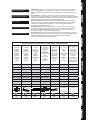
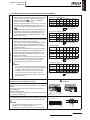
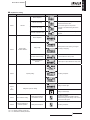
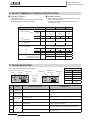
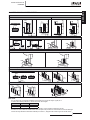
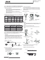
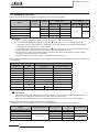
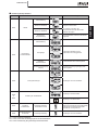
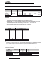
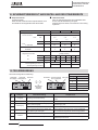
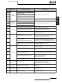
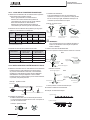
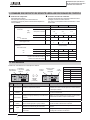
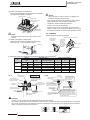
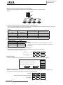
MODELS CODIFICATION
Important note: Please, check, according to the model name, which is your air conditioner
type, how it is abbreviated and referred to in this instruction manual. This Installation and
Operation Manual is only related to Indoor Units FSN(2)(M)(E) combined with Outdoor Units
HRNM.
CODIFICACIÓN DE MODELOS
Nota importante: compruebe, de acuerdo con el nombre del modelo, el tipo de sistema
de aire acondicionado del que dispone, su abreviatura y su referencia en el presente manual de
instrucciones. Este Manual de instalación y funcionamiento sólo está relacionado con unidades
interiores FSN(2)(M)(E) combinadas con unidades externas HRNM.
MODELLCODES
Wichtiger Hinweis: Bitte stellen Sie anhand der Modellbezeichnung den Klimaanlagentyp
und das entsprechende, in diesem Technischen Handbuch verwendete Kürzel fest. Dieses
Installations- und Betriebshandbuch bezieht sich nur auf FSN(2)(M)(E)-Innengeräte in
Kombination mit HRNM. -Außengeräten.
CODIFICATION DES MODÈLES
Note importante : Veuillez déterminer, d’après le nom du modèle, quel est votre type de
climatiseur et quelle est son abréviation et référence dans le présent manuel d’instruction.
Ce manuel d’installation et de fonctionnement ne concernent que les unités intérieures
FSN(2)(M)(E) combinées à des groupes extérieurs HRNM.
CODIFICAZIONE DEI MODELLI
Nota importante: in base al nome del modello, vericare il tipo di climatizzatore in possesso
nonché il tipo di abbreviazione e di riferimento utilizzati in questo manuale di istruzioni. Questo
manuale di installazione e di funzionamento fa riferimento alla sola combinazione
di unità interne FSN(2)(M)(E) e unità esterne HRNM.
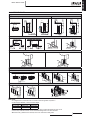
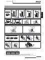
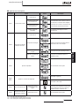
INDOOR UNIT · UNIDAD INTERIOR · INNEINHEIT · UNITÉ INTERIEUR · UNITÀ INTERNA · UNIDADE INTERIOR
Cassette
Empotrado
Kassette
Cassete
A Cassetta
Cassete
Kassette
Cassette
Kassett
Κασέτας
Cassette
Empotrado
Kassette
Cassete 2 vois
A Cassetta
Cassete
Kassette
Cassette
Kassett
Κασέτας
Ceiling
Techo
Deckengerät
plafonnier
A softto
Tecto
Lofthængt
Plafondmodel
I taket
Οροφής
In the ceiling
Conducto
Deckeneinbau
Gainable
A controsoftto
Encastrar no tecto
I loftet
Inbouwversie
I taket
Εσωτερικού
οροφής
Wall Type
Tipo mural
Wandgerät
Type mural
Tipo a parete
Tipo mural
Vægmodel
Wandmodel
Väggmodell
Τοίχου
Floor Type
De pie
Stand
Sol
Modello verticale
Pavimento
Gulv
Vloermodel
Golv
Δαττεδου
Floor Concealed
Type
De pie oculto
Stand-Einbau
Sol encastré
Modello verticale a
incasso
Embutido
Gulvpanel
Inbouw-vloermodel
Inbyggd golvtyp
Kρuφή Δαττεδου
RCIM-2.0FSN2
RCI-2.0FSN2E RCD-2.0FSN2 RPC-2.0FSN2E RPI-2.0FSN2E RPK-2.0FSN2M RPF-2.0FSN2E RPFI-2.0FSN2E
RCI-2.5FSN2E RCD-2.5FSN2 RPC-2.5FSN2E RPI-2.5FSN2E RPK-2.5FSN2M RPF-2.5FSN2E RPFI-2.5FSN2E
RCI-3.0FSN2E RCD-3.0FSN2 RPC-3.0FSN2E RPI-3.0FSN2E RPK-3.0FSN2M
RCI-4.0FSN2E RCD-4.0FSN2 RPC-4.0FSN2E RPI-4.0FSN2E RPK-4.0FSN2M
RCI-5.0FSN2E RCD-5.0FSN2 RPC-5.0FSN2E RPI-5.0FSN2E
RCI-6.0FSN2E RPC-6.0FSN2E RPI-6.0FSN2E
RPI-8.0FSN2E
RPI-10.0FSN2E
1~ 1~ 1~ 1~ 1~ 1~ 1~
RCI RCD RPC RPI RPK RPF RPFI

CODIFICAÇÃO DE MODELOS
Nota Importante: por favor, verique, de acordo com o nome do modelo, qual é o seu tipo de
ar condicionado, e como este é abreviado e mencionado neste manual de instruções. Este
manual de instalação e de funcionamento só está relacionado com a unidade interior FSN(2)(M)
(E) combinada com as unidades exteriores HRNM.
MODELKODIFICERING
Vigtig information: Kontroller modelnavnet på dit klimaanlæg for at se, hvilken type
klimaanlæg du har, hvordan det forkortes, og hvordan der henvises til det i denne vejledning.
Denne bruger- og monteringsvejledning gælder kun FSN(2)(M)(E)-indendørsenheder
kombineret med HRNM.-udendørsenheder.
CODERING VAN DE MODELLEN
Belangrijke opmerking: Controleer aan de hand van de modelnaam welk type airconditioner u
heeft, hoe de naam wordt afgekort en hoe ernaar wordt verwezen in deze instructie-handleiding.
Deze Installatie- en bedieningshandleiding heeft alleen betrekking op binnenunits FSN(2)(M)(E)
gecombineerd met buitenunits HRNM.
MODELLER
Viktigt! Kontrollera med modellnamnet vilken typ av luftkonditionering du har, hur den förkortas
och hur den anges i den här handboken. Denna handbok för installation och användning gäller
endast för inomhusenheter FSN(2)(M)(E) kombinerade med utomhusenheter HRNM.
ΚΩΔΙΚΟΠΟΙΗΣΗ ΜΟΝΤΕΛΩΝ
: Ελέγξτε, σύμφωνα με το όνομα μοντέλου, τον τύπο του δικού σας
κλιματιστικού και με ποια σύντμηση δηλώνεται και αναφέρεται σε αυτό το εγχειρίδιο. Αυτό το
εγχειρίδιο εγκατάστασης και λειτουργίας αφορά μόνο τις Εσωτερικές Μονάδες FSN(2)(M)(E) σε
συνδυασμό με Εξωτερικές Μονάδες HRNM.
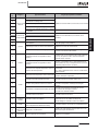
OUTDOOR UNIT · UNIDAD EXTERIOR · AUßENEINHEIT · UNITÉ EXTÉRIEURE · UNITÀ ESTERNA ·
UNIDADE EXTERIOR · UDENDÆRS AGGREGAT · BUITENTOESTEL · UTOMHUSENHET · ΕΞΩΤΕΡΙΚΗ ΜΟΝΑΔΑ
HEAT PUMP MODELS
MODELOS CON BOMBA DE CALOR
WÄRMEPUMPENMODELLE
MODÈLES POMPE À CHALEUR
MODELLI POMPA DI CALORE
MODELOS BOMBA DE CALOR
VARMEPUMPEMODELLER
MODELLEN MET WARMTEPOMP
MODELLER ENDAST FÖR KYLNINGSFUNKTION
ΜΟΝΤΕΛΑ ΜΕ ΑΝΤΛΙΑ ΘΕΡΜΟΤΗΤΑΣ
Three Phase
Trifásico
Dreiphasig
Triphasé
Trifase
Trifásico
Trefaset
Driefasig
Trefasig
Τριών φάσεων
RAS-8HRNM
RAS-10HRNM
RAS-12HRNM
3~
RAS

15
PMML0129A rev.4 - 02/2010
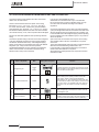
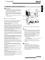
ENGLISH
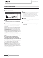
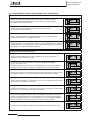
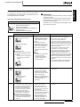
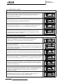
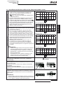
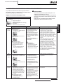
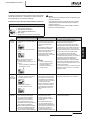
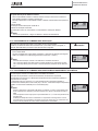
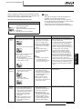
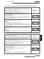
DANGER:
- Do not pour water into the indoor or outdoor unit. These
products are equipped with electrical parts. If water
contacts with electrical components then it will cause a
serious electrical shock.
- Do not touch or adjust safety devices inside the indoor or
outdoor units. If these devices are touched or adjusted, it
may cause a serious accident.
-
Do not open the service cover or access the indoor or
outdoor units without disconnecting the main power supply.
- In case of re Turn OFF the main switch, put out the re
at once and contact your service contractor.
- Check that the ground wire is securely connected.
- Connect a fuse of specied capacity.
CAUTION:
- Refrigerant leakage can cause difculty with breathing
due to insufcient air.
-
Do not install the indoor unit, outdoor unit, remote control
switch and cable within approximately 3 meters from strong
electromagnetic wave radiators such as medical equipment.
- This appliance must be used only by adult and capable
people, having received the technical information or
instructions to handle properly and safely this appliance.
WARNING:
- Do not use any sprays such as insecticide, lacquer, hair
spray or other ammable gases within approximately one
(1) meter from the system.
- If circuit breaker or fuse is often activated, stop the
system and contact your service contractor.
- Do not make service or inspections tasks by yourself. This
works must be performed by qualied service person.
- Do not put any strange material (sticks, etc...) into the air
inlet and outlet. These units have high speed rotating fans
and it is dangerous that any object touches them.
NOTE:
It is recommended to ventilate the room every 3 or 4 hours.
1. SAFETY SUMMARY
2. IMPORTANT NOTICE
■ Verify, in accordance with the manuals which appear in the
outdoor and indoor units, that all the information required for
the correct installation of the system is included. If this is not
the case, contact your distributor.
■ HITACHI pursues a policy of continuing improvement in
design and performance of products. The right is therefore
reserved to vary specications without notice.
■ HITACHI cannot anticipate every possible circumstance that
might involve a potential hazard.
■ This air conditioner has been designed for standard air
conditioning for human beings only. Do not use this for other
purposes such as for drying clothes, refrigerating foods or for
any other cooling or heating process.
■ No part of this manual may be reproduced without written
permission.
■ If you have any questions, contact your service contractor of
HITACHI.
■ Check and make sure that the explanations of each part of
this manual correspond to your air conditioner model. The
items which are not applicable to all the models are claried
in the text («only heat pump models», etc).
■ Refer to the models codication to conrm the main
characteristics of your system.
■ Signal words (DANGER, WARNING and CAUTION) are
used to identify levels of hazard seriousness. Denitions
for identifying hazard levels are provided below with their
respective signal words.
■ It is assumed that this unit will be operated and serviced by
English speaking people. If this is not the case, the customer
should add safety, caution and operating signs in the native
language of the personal.
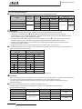
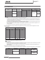
■ This air conditioner has been designed for the following
temperature. Operate the air conditioner within this range:
Temperature
Maximum Minimum
Cooling
Mode
Indoor 32 °C DB / 23 °C WB 21 °C DB/15 °C WB
Outdoor 43 °C DB -15 °C DB
Heating
Mode
Indoor 30 °C DB 15 °C DB
Outdoor 17 °C WB -20 °C WB
DB: Dry Bulb Temperature
WB: Wet Bulb Temperature
■ These operations modes are controlled by the remote control
switch.
■ This manual should be considered as a permanent part of the
air conditioner. This manual gives a common description and
information for this air conditioner which you operate as well
as for other models.
CAUTION:
This unit is designed for commercial and light industrial
application. If installed in house hold appliance, it could
cause electromagnetic interference.
SAFETY SUMMARY

16
PMML0129A rev.4 - 02/2010
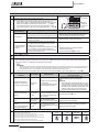
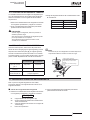
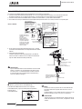
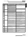
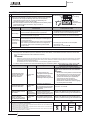
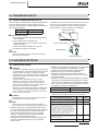
IMPORTANT NOTICE
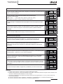
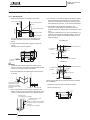
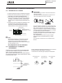
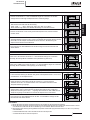
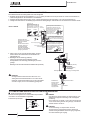
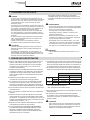
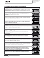
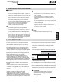
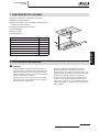
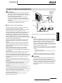
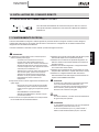
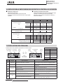
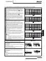
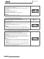
DANGER:
- Pressure Vessel and Safety Device: This air conditioner
is equipped with a high pressure vessel under PED
(Pressure Equipment Directive). The pressure vessel
has been designed and tested before shipment according
to PED. Also, in order to prevent the system from an
abnormal pressure, a high pressure switch, which needs
no eld adjustment, is utilized in the refrigeration system.
Therefore, this air conditioner is protected from abnormal
pressures. However, if abnormally high pressure is
applied to the refrigeration cycle including the high
pressure vessel(s), it will result in serious injury or death
due to explosion of the pressure vessel. Do not apply a
pressure higher than the following pressure to the system,
by modifying or changing the high pressure switch.
- Start-up and Operation: Check to ensure that all the
stop valves are fully opened and no obstacle exists at the
inlet/outlet sides before start-up and during the operation.
- Maintenance: Periodically check the high pressure side
pressure. If the pressure is higher than the maximum
allowable pressure, stop the system and clean the heat
exchanger or remove the cause.
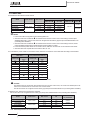
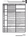
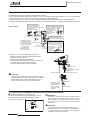
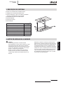
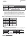
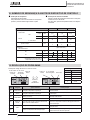
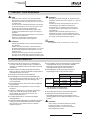
- Maximum Allowable Pressure and High Pressure Cut-out Value:
Product Series
Outdoor Unit
Model
Refrigerant
Maximum Allowable
Pressure (MPa)
High Pressure
Switch Cut-out
Value (MPa)
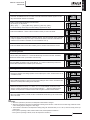
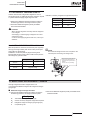
HRNM Series RAS-8~12HRNM R410A 4.15 4.00 ~ 4.10
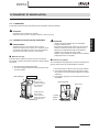
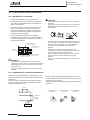
NOTE:
The label for the vessel under PED are attached on the
high pressure vessel. The pressure vessel capacity and
vessel category are indicated on the vessel.
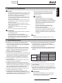
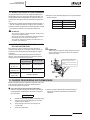
NOTE:
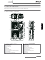
The high pressure switch is indicated on the electrical
wiring diagram in the outdoor unit as “PSH” connected to
printed circuit board (PCB1) in the outdoor unit.
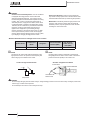
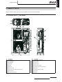
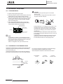
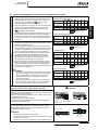
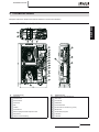
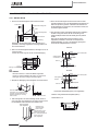
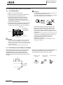
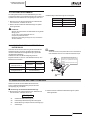
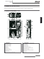
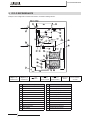
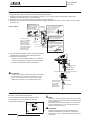
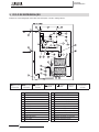
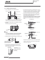
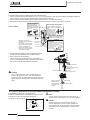
Location of High Pressure Switch Structure of High Pressure Switch
DANGER:
− Do not change the high-pressure switch locally or change the high pressure cut-out set value locally. If changed, it will cause
serious injury or death due to explosion.
− Do not attempt to turn service valve rod beyond its stop
Compressor
Contact Point
Pressure detected
Conected to the
electrical wire

17
PMML0129A rev.4 - 02/2010
ENGLISH
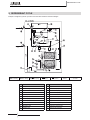
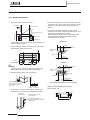
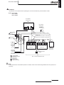
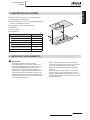
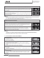
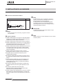
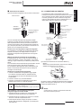
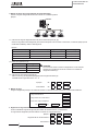
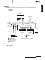
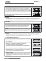
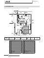
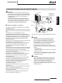
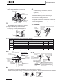
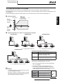
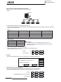
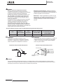
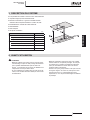
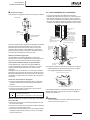
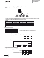
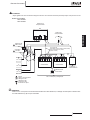
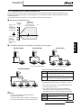
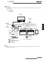
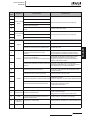
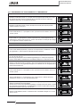
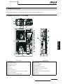
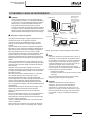
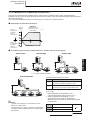
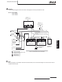
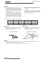
3. SYSTEM DESCRIPTION
■ Maximum 4 Indoor Unit can be controlled.
■ Long piping for high-rise buildings.
■ Various combinations, 7 types and 34 models of indoor units
type and capacity from 5.0 kW to 25.0kW.
■ Flexibility of indoor unit control.
■ Space saving.
■ Easy installation.
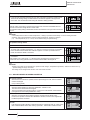
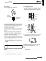
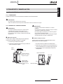
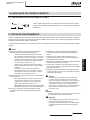
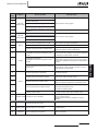
(m)
UNIT POWER
RAS-8
~12HRNM
Maximum Piping Length Lo-i
Actual Length 100
Equivalent Length 120
Maximum Piping Length Ho-i
Outdoor Unit is higher than Indoor Unit 30
Indoor Unit is higher than Outdoor Unit 20
Maximum piping Lift Hi-i 3
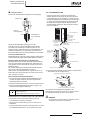
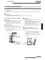
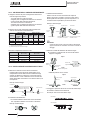
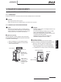
4. BEFORE OPERATION
CAUTION:
- Supply electrical power to the system for approximately
12 hours before start-up or a long shutdown. Do not start
the system immediately after power supply, it may cause
a compressor is not heated well.
- When the system is started after a shutdown longer that
approximately 3 months, it is recommended to check the
system by your service contractor.
- Turn OFF the main switch when the system is to be
stopped for a long period of time: If the main switch is
not turned OFF, electricity will be used, because the oil
heater is always energised during compressor stopping.
- Make sure that the outdoor unit is not covered with
snow or ice. If covered, remove it by using hot water
(approximately 50 ºC). If the water temperature is higher
that 50 ºC, it will cause damage to plastic parts.
SYSTEM DESCRIPTION

18
PMML0129A rev.4 - 02/2010
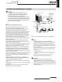
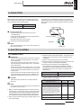
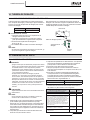
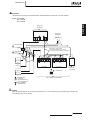
REMOTE CONTROLLER
OPERATION
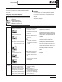
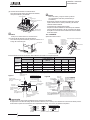
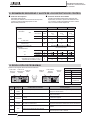
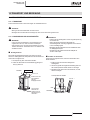
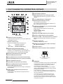
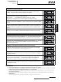
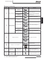
5 REMOTE CONTROLLER OPERATION
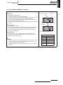
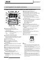
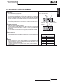
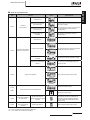
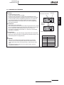
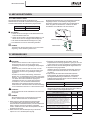
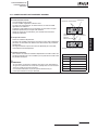
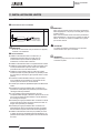
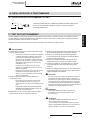
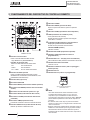
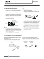
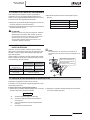
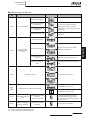
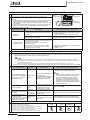
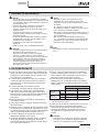
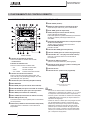
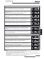
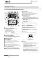
5.1. OPTIONAL LIQUID CRYSTAL REMOTE CONTROL (PC-ART)
Model: PC-ART
Fan speed indicator
It indicates the fan speed you have selected:
- (High / Medium / Low)
Indicator of Total ventilator
It indicates if Total ventilator has been selected.
- A/C only air conditioning
- VENTI only ventilation
- A/C + VENTI if both are selected
Operation Mode Indicator
Indicates the operation mode selected:Fan/Cool/Heat/Dry/
Auto (Cool/Heat)
Run indicator (Red lamp)
RUN/STOP Switch
MODE (Operation Mode Selection) Switch
FAN SPEED (Fan Speed Selection) Switch
Up & Down Panel Operation Switch
VENTI (Ventilator Operation) Switch
LOUVER (Swing Louver Operation) Switch
TIME (Time setting) switch
Increase and decreases the set Time for timer operation.
ON/OFF TIMER (Timer Operation) Indicator
Used to activate or deactivate the timer operation.
CHECK Switch
RESET (Filter Reset) Switch
After cleaning the air lter, press the “RESET” button.
TEMP (Temperature Setting) Switch
T.RUN (Test Run Indication)
Check (Check Indication)
These tests appear when “TEST RUN” or “CHECK” is being
performed.
cleaning time will by set.
It also stops the run procedure
ABNML (Alarm) Indicator
“FILTER” Indicator
SET TEMP (Setting Temperature) Indicator
12345S indicator (setting schedule number)
Mon Tue ... Sun indicator (Day of the week indicator).
Indicates that central station or CS-Net control is being
performed.
Swing louver indicator
“DEFROST” is indicated
SERVICE mode indicator. (Indicates the change to
special operations)
Time indicator.
Time indicator. (Indicates the programmed time).
When opening the cover, pull the
cover toward the arrow direction.
NOTE:
- If the case that the LOW fan speed is selected and outdoor
temperature is higher than 21°C, excessive load is given to
the compressor at heating operation.
Therefore, set the fan speed at HIGH or MEDIUM, since
safety devices may be activated.
- When the system is started after a shutdown longer than
approximately 3 months, it is recommended that the
system be checked by your service contractor.
- Turn OFF the main switch when the system is stopped for
a long period of time. Otherwise the system consumes
electricity as the oil heater remains active even though the
compressor is stopped.

19
PMML0129A rev.4 - 02/2010
ENGLISH
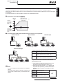
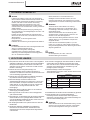
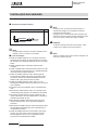
■ Before Operation
■ Supply electrical power to the system for approximately 12 hours before start-up or a long
shutdown. Do not start the system immediately after power supply, it may cause a compressor
failure because the compressor is not heated well.
■ Make sure that the outdoor unit is not covered with snow or ice. If covered, remove it by using
hot water (less than 50°C).
■ If the water temperature is higher that 50°C, it will cause damage to plastic parts.
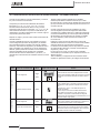
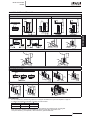
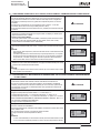
CAUTION
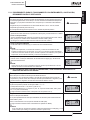
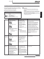
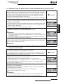
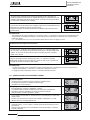
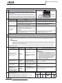
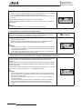
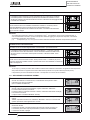
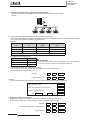
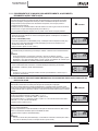
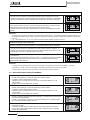
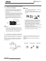
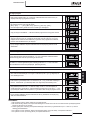
1. Turn on the power supply.
Three vertical lines appear on the liquid crystal display A/C or VENTI is indicated on the liquid
crystal display.
2. Press the MODE switch.
By repeatedly pressing the MODE switch, the indication is changed in order of COOL, HEAT,
DRY and FAN (In case of Cooling Only model, COOL, DRY and FAN).
(The gure shows when setting "COOL" mode is selected).
3. Press RUN/STOP Switch.
Then red LED turns ON. The system is automatically started.
NOTE:
Setting of Temperature, Fan Speed and Air Louver Direction.
The setting condition is memorized after setting once, therefore the daily setting is not
required. In case that the setting is required to be changed, refer to “operation procedure for
Temperature, Fan Speed and Air Louver Direction Setting”.
4. Switch OFF (STOP)
Press the RUN/STOP switch again. The RUN indicator (Red) is OFF. The system is
automatically stopped.
NOTE:
There could be a case that the fan operation is performed for approximately 2 minutes after
the heating operation is stopped.
5.1.1. OPERATION PROCEDURE FOR COOLING, HEATING, DRY AND FAN OPERATIONS
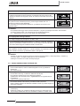
5.1.2. OPERATION PROCEDURE FOR TEMPERATURE, FAN SPEED AND AIR LOUVER DIRECTION SETTING
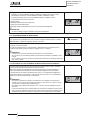
■ DO NOT touch the CHECK switch.
■ The CHECK switch is used only when servicing.
■ In case that the CHECK switch is pressed by mistake and the operation mode is changed to
the check mode, press the CHECK switch again for approximately 3 seconds, and press the
CHECK switch once again after 10 seconds: the mode will change back to normal.
ATTENTION
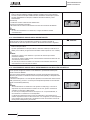
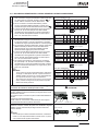
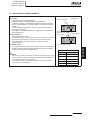
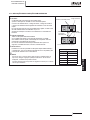
■ Temperature Setting
■ Adjust the temperature by pressing TEMP “” or “” switch.
■ The temperature is increased by 1º C by pressing switch (max 30 °C).
■ The temperature decreases by 1º C by pressing switch (min. 19 °C for COOL, DRY and FAN
modes; min. 17 °C for HEAT mode).
(The gure shows when setting 28 °C).
■ Setting FAN Speed
■ Press the FAN SPEED switch.
■ When the FAN SPEED switch is pressed repeatedly, the indication changes in the rotation of
HIGH, MEDIUM and LOW
■ For standard operation, set the fan speed at HIGH.
■ (The gure shows when setting “MED” speed).
NOTE:
In case of DRY mode, the fan speed is automatically changed to LOW, and can not be
changed. (However, the indication shows the present setting condition).
REMOTE CONTROLLER
OPERATION

20
PMML0129A rev.4 - 02/2010
REMOTE CONTROLLER
OPERATION
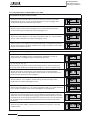
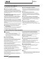
■ Setting of Swing Louver Direction
Press the SWING LOUVER switch: el deector oscilante inicia su funcionamiento. Press
the SWING LOUVER switch again, the swing louver is xed. By repeatedly pressing the
SWING LOUVER switch, the swing louver repeats to stop and swing.
■ When Fixed
The indication shows the air ow direction.
■ When Swinging Automatically
The indications move continuously corresponding to the louver swing.
NOTE:
In the heating operation, the louver angle changes automatically.
5.1.3. OPERATION PROCEDURE FOR VENTILATION
This function is available only when the total heat exchanger is connected.
When the procedures below are performed without the total heat exchanger connected, “NO
FUNCTION” blinks for 5 seconds.
ATTENTION
■ Ventilation
Press the VENTI switch
By repeatedly pressing the VENTI switch, the indication is changed in order of A/C,
VENTI and A/C+VENTI. (La gura muestra el estado cuando el ajuste es “A/C + VENTI”).
NOTE:
Contact your distributor or dealer of HITACHI for detailed information.
In case that the mode is changed to VENTI during individual operation of the air
conditioner, the air conditioner is stopped.
In case that the mode is changed to A/C during individual operation of the total heat
exchanger, the total heat exchanger is stopped.
5.1.4. OPERATION PROCEDURE FOR AUTOMATIC COOLING / HEATING OPERATION
The automatic cooling/heating operation is required to be set by the optional function. Contact
your distributor or dealer of HITACHI for detailed information.
This function is to change operation mode, cooling or heating automatically according to the
temperature difference between the set temperature and the suction air temperature.
In the case that the suction air temperature is higher than the set temperature by 3 C,
the operation is changed to COOL mode, and lower than the set temperature by 3 C, the
operation is changed to HEAT mode.
NOTE:
In case of heating operation at the LOW fan speed, the operation often stops by the
operation of the protective devices. In this case, set the fan speed to HIGH or MED.
In case that the outdoor temperature is higher than approximately 21°C, the heating
operation is not available.
The temperature difference between cooling and heating operation is quite big in case of
using this function. Therefore, this function can not be used for the air conditioning of the
room where requires accurate control of temperature and humidity.

21
PMML0129A rev.4 - 02/2010
ENGLISH
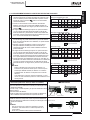
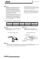
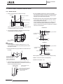
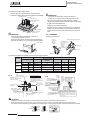
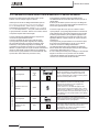
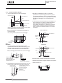
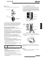
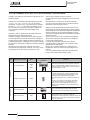
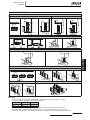
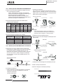
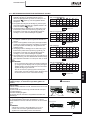
5.1.5. OPERATION PROCEDURE FOR SWING LOUVER ADJUSTMENT
Setting Swing Louver
1. When the SWING LOUVER switch is pressed, the swing
louver starts its operation. The range of the angle of swing
is approximately 70° from the horizontal to the vertical
position. When mark “ ” is moving, it indicates the
operation of the louver continuously.
2. When the swinging operation of the louver is not required,
press the SWING LOUVER switch again. The louver is
stopped at an angle indicated by the direction of the mark
“ ”.
3. Discharge air angle is xed (at 20° for RCI series and 40°
for RCD series) during start-up of heating operation and
defrosting operation when thermostat is ON. When the
outlet air temperature exceeds approximately 30 °C, the
louvers start to swing.
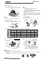
RCI (4-way cassette type)
Indication
Louver angle
(approx.)
Approx.
20°
Approx.
25°
Approx.
30°
Approx.
35°
Approx.
45°
Approx.
55°
Approx.
70°
Cooling Dry
Heating
: Recommended angle
RCD (2-way cassette type)
Indication
Louver angle
(approx.)
Approx.
40°
Approx.
45°
Approx.
50°
Approx.
55°
Approx.
60°
Approx.
65°
Approx.
70°
Cooling Dry
Heating
: Recommended angle
RPK (Wall Type)
Indication
Louver angle
(approx.)
Approx.
35°
Approx.
40°
Approx.
45°
Approx.
50°
Approx.
55°
Approx.
60°
Approx.
70°
Cooling Dry
Louver angle
(approx.)
Approx.
40°
Approx.
45°
Approx.
50°
Approx.
55°
Approx.
60°
Approx.
65°
Approx.
70°
Heating
: Recommended angle
RPC (Ceiling Type)
Indication
Louver angle
(approx.)
Horizontal
Approx.
15°
Approx.
30°
Approx.
40°
Approx.
50°
Approx.
60°
Approx.
80°
Cooling Dry
Heating
: Recommended angle
Angle Range
Angle Range
Angle Range
Angle Range
Angle Range
Angle Range
Angle Range
Angle Range
Fixing the louver
1. In the case of cooling and dry operation, discharge air
angle can be changed at 5 positions. In the case of heating
operation, it can be changed at 7 positions
2. To x the louver position, rst press the SWING LOUVER
switch to start the louver swinging, and then press the
SWING LOUVER switch again when the louver reaches
the required position.
3. Discharge air angle is xed (at 20° for RCI series and 40°
for RCD series) during start-up of heating operation and
defrosting operation when thermostat is ON. When the
outlet air temperature exceeds approxima-tely 30 °C, the
swing louvers activate.
4. When the louvers are xed at an angle 55° RCI, 65° RCD
or 70° both during heating operation and the operation
mode is changed to cooling operation, louvers will be
automatically xed at an angle 45° RCI, 60° RCD.
NOTE:
There exists a time lag between the actual angle of the
louver and the liquid crystal indication. When the SWING
LOUVER switch is pressed, the louver will not stop
immediately. The louver will move one extra swing.
If the louvers are moced due to cleaning or for any
reason, setAuto Seting mode to take the four louvers in
the same position.
Do not turn the air louver by hand. Otherwise the louver
mechanism would be damaged (in all units).
CAUTION
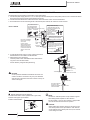
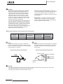
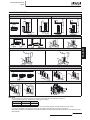
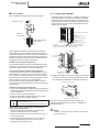
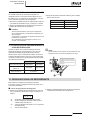
Wall Type (RPK):
Adjust the vertical louvers by hand to discharge air in the required
direction.
Do not swing 1 blade at left side and 2 blade at right side of the
vertical deection.
Automatic Setting of louver
When the unit operation is stopped, two air louvers are stopped at
closing position automatically.
Ceiling Type (RPC):
The vertical deector consists of four sets of deectors. Adjust the
vertical louvers by hand to discharge air in the required direction.
NOTE:
For models without automatic swing louver the above
indications are not available through R.C.S.
The swing Louver should be adjusted by hand in this case.
Horizontal Deector
Vertical louver
One Set
Louver
vertical
Horizontal Deector
REMOTE CONTROLLER
OPERATION

22
PMML0129A rev.4 - 02/2010
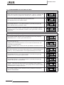
5.1.6. TIMER OPERATION PROCEDURE
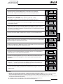
■ Setting current day and time
1. Hold down the DAY switch for more than 3 seconds to change to current day setting mode.
SET is indicated and the day blinks. All the days except the current day are indicated.
:
SET
Mon Tue
Wed
Thu
Fri
Sat
Sun
2. Press DAY switch until the actual day ickers, then press OK switch.
Selected day is indicated and “time” ickers.
:
SET
Mon Tue
Wed
Thu
Fri
Sat
Sun
3. Press the SELECT switch to adjust the “hour” setting, and then press again. “Hour” is
indicated and “minutes” ickers.
:
SET
Wed
4. Press switch to adjust “minutes”, and when adjusted press OK switch. The current time
setting mode ends and returns to normal mode. “Minutes” is indicated and SET is lighted off.
“Seconds” starts from zero.
:
Wed
■ Setting the timer (programming)
1. Press the TIMER switch. SET and SCHEDULE are indicated.Schedule Number “1” ickers and
other numbers are indicated.
:
SET
1234S
SCHEDULE
ON
OFF
:
2. When the schedule switch is pressed , the schedule number moves
[1]→[2]→[3]→[4]→[S]→[1]….
− Select [S] to set the ON/OFF time and temperature shifts.
− *By pressing TIMER switch, SET and SCHEDULE are lighted off and changed to normal mode.
:
SET
1234S
ADDS
SCHEDULE
RNkHR
ON
OFF
:
3. When the OK switch is pressed, the selected schedule number is indicated. Other schedule
number are lighted off, and “Hour” of ON time for the selected schedule Number ickers.
:
SET
1
SCHEDULE
ON
OFF
:
4. Press the SELECT to adjust the “minutes” setting, and then press again. “Hour” is
indicated and “minutes” ickers.
:
SET
1
SCHEDULE
ON
OFF
:
5. Press the SELECT switch to adjust the “minutes” setting, and then press again. “Minutes”
is indicated and “hour” of OFF time ickers.
:
SET
1
SCHEDULE
ON
OFF
:
6. Set the OFF time the same way as the ON time. After setting “minutes”, OFF time is indicated.
If the schedule number [1][2][3][4] is selected, the indication changes to set the schedule
number shown in 2. If [S] is selected, see the section on setting temperature shifts for details.
:
SET
1
SCHEDULE
ON
OFF
:
7. When the TIMER switch is pressed, the SET and SCHEDULE indicators go out and the mode
returns to normal.
:
S
NEXT
SCHEDULE
OFF
:
Mon
REMOTE CONTROLLER
OPERATION
La pagina si sta caricando...
La pagina si sta caricando...
La pagina si sta caricando...
La pagina si sta caricando...
La pagina si sta caricando...
La pagina si sta caricando...
La pagina si sta caricando...
La pagina si sta caricando...
La pagina si sta caricando...
La pagina si sta caricando...
La pagina si sta caricando...
La pagina si sta caricando...
La pagina si sta caricando...
La pagina si sta caricando...
La pagina si sta caricando...
La pagina si sta caricando...
La pagina si sta caricando...
La pagina si sta caricando...
La pagina si sta caricando...
La pagina si sta caricando...
La pagina si sta caricando...
La pagina si sta caricando...
La pagina si sta caricando...
La pagina si sta caricando...
La pagina si sta caricando...
La pagina si sta caricando...
La pagina si sta caricando...
La pagina si sta caricando...
La pagina si sta caricando...
La pagina si sta caricando...
La pagina si sta caricando...
La pagina si sta caricando...
La pagina si sta caricando...
La pagina si sta caricando...
La pagina si sta caricando...
La pagina si sta caricando...
La pagina si sta caricando...
La pagina si sta caricando...
La pagina si sta caricando...
La pagina si sta caricando...
La pagina si sta caricando...
La pagina si sta caricando...
La pagina si sta caricando...
La pagina si sta caricando...
La pagina si sta caricando...
La pagina si sta caricando...
La pagina si sta caricando...
La pagina si sta caricando...
La pagina si sta caricando...
La pagina si sta caricando...
La pagina si sta caricando...
La pagina si sta caricando...
La pagina si sta caricando...
La pagina si sta caricando...
La pagina si sta caricando...
La pagina si sta caricando...
La pagina si sta caricando...
La pagina si sta caricando...
La pagina si sta caricando...
La pagina si sta caricando...
La pagina si sta caricando...
La pagina si sta caricando...
La pagina si sta caricando...
La pagina si sta caricando...
La pagina si sta caricando...
La pagina si sta caricando...
La pagina si sta caricando...
La pagina si sta caricando...
La pagina si sta caricando...
La pagina si sta caricando...
La pagina si sta caricando...
La pagina si sta caricando...
La pagina si sta caricando...
La pagina si sta caricando...
La pagina si sta caricando...
La pagina si sta caricando...
La pagina si sta caricando...
La pagina si sta caricando...
La pagina si sta caricando...
La pagina si sta caricando...
La pagina si sta caricando...
La pagina si sta caricando...
La pagina si sta caricando...
La pagina si sta caricando...
La pagina si sta caricando...
La pagina si sta caricando...
La pagina si sta caricando...
La pagina si sta caricando...
La pagina si sta caricando...
La pagina si sta caricando...
La pagina si sta caricando...
La pagina si sta caricando...
La pagina si sta caricando...
La pagina si sta caricando...
La pagina si sta caricando...
La pagina si sta caricando...
La pagina si sta caricando...
La pagina si sta caricando...
La pagina si sta caricando...
La pagina si sta caricando...
La pagina si sta caricando...
La pagina si sta caricando...
La pagina si sta caricando...
La pagina si sta caricando...
La pagina si sta caricando...
La pagina si sta caricando...
La pagina si sta caricando...
La pagina si sta caricando...
La pagina si sta caricando...
La pagina si sta caricando...
La pagina si sta caricando...
La pagina si sta caricando...
La pagina si sta caricando...
La pagina si sta caricando...
La pagina si sta caricando...
La pagina si sta caricando...
La pagina si sta caricando...
La pagina si sta caricando...
La pagina si sta caricando...
La pagina si sta caricando...
La pagina si sta caricando...
La pagina si sta caricando...
La pagina si sta caricando...
La pagina si sta caricando...
La pagina si sta caricando...
La pagina si sta caricando...
La pagina si sta caricando...
La pagina si sta caricando...
La pagina si sta caricando...
La pagina si sta caricando...
La pagina si sta caricando...
La pagina si sta caricando...
La pagina si sta caricando...
La pagina si sta caricando...
La pagina si sta caricando...
La pagina si sta caricando...
La pagina si sta caricando...
La pagina si sta caricando...
La pagina si sta caricando...
La pagina si sta caricando...
La pagina si sta caricando...
La pagina si sta caricando...
La pagina si sta caricando...
La pagina si sta caricando...
La pagina si sta caricando...
La pagina si sta caricando...
La pagina si sta caricando...
La pagina si sta caricando...
La pagina si sta caricando...
La pagina si sta caricando...
La pagina si sta caricando...
La pagina si sta caricando...
La pagina si sta caricando...
La pagina si sta caricando...
La pagina si sta caricando...
La pagina si sta caricando...
La pagina si sta caricando...
La pagina si sta caricando...
La pagina si sta caricando...
La pagina si sta caricando...
La pagina si sta caricando...
La pagina si sta caricando...
La pagina si sta caricando...
La pagina si sta caricando...
La pagina si sta caricando...
La pagina si sta caricando...
La pagina si sta caricando...
La pagina si sta caricando...
La pagina si sta caricando...
La pagina si sta caricando...
La pagina si sta caricando...
La pagina si sta caricando...
La pagina si sta caricando...
La pagina si sta caricando...
La pagina si sta caricando...
La pagina si sta caricando...
La pagina si sta caricando...
La pagina si sta caricando...
La pagina si sta caricando...
La pagina si sta caricando...
La pagina si sta caricando...
La pagina si sta caricando...
La pagina si sta caricando...
La pagina si sta caricando...
La pagina si sta caricando...
La pagina si sta caricando...
La pagina si sta caricando...
La pagina si sta caricando...
La pagina si sta caricando...
La pagina si sta caricando...
La pagina si sta caricando...
La pagina si sta caricando...
La pagina si sta caricando...
La pagina si sta caricando...
La pagina si sta caricando...
La pagina si sta caricando...
La pagina si sta caricando...
La pagina si sta caricando...
La pagina si sta caricando...
La pagina si sta caricando...
La pagina si sta caricando...
La pagina si sta caricando...
La pagina si sta caricando...
La pagina si sta caricando...
La pagina si sta caricando...
La pagina si sta caricando...
La pagina si sta caricando...
La pagina si sta caricando...
La pagina si sta caricando...
La pagina si sta caricando...
La pagina si sta caricando...
La pagina si sta caricando...
La pagina si sta caricando...
La pagina si sta caricando...
La pagina si sta caricando...
La pagina si sta caricando...
La pagina si sta caricando...
La pagina si sta caricando...
La pagina si sta caricando...
La pagina si sta caricando...
La pagina si sta caricando...
La pagina si sta caricando...
La pagina si sta caricando...
La pagina si sta caricando...
La pagina si sta caricando...
La pagina si sta caricando...
La pagina si sta caricando...
La pagina si sta caricando...
La pagina si sta caricando...
La pagina si sta caricando...
La pagina si sta caricando...
La pagina si sta caricando...
La pagina si sta caricando...
La pagina si sta caricando...
La pagina si sta caricando...
La pagina si sta caricando...
La pagina si sta caricando...
La pagina si sta caricando...
La pagina si sta caricando...
La pagina si sta caricando...
La pagina si sta caricando...
La pagina si sta caricando...
La pagina si sta caricando...
La pagina si sta caricando...
La pagina si sta caricando...
La pagina si sta caricando...
La pagina si sta caricando...
La pagina si sta caricando...
La pagina si sta caricando...
La pagina si sta caricando...
La pagina si sta caricando...
La pagina si sta caricando...
La pagina si sta caricando...
La pagina si sta caricando...
La pagina si sta caricando...
La pagina si sta caricando...
La pagina si sta caricando...
La pagina si sta caricando...
La pagina si sta caricando...
La pagina si sta caricando...
La pagina si sta caricando...
La pagina si sta caricando...
La pagina si sta caricando...
La pagina si sta caricando...
La pagina si sta caricando...
La pagina si sta caricando...
La pagina si sta caricando...
La pagina si sta caricando...
La pagina si sta caricando...
La pagina si sta caricando...
La pagina si sta caricando...
La pagina si sta caricando...
La pagina si sta caricando...
La pagina si sta caricando...
La pagina si sta caricando...
La pagina si sta caricando...
La pagina si sta caricando...
La pagina si sta caricando...
La pagina si sta caricando...
La pagina si sta caricando...
La pagina si sta caricando...
La pagina si sta caricando...
La pagina si sta caricando...
La pagina si sta caricando...
La pagina si sta caricando...
La pagina si sta caricando...
La pagina si sta caricando...
La pagina si sta caricando...
La pagina si sta caricando...
La pagina si sta caricando...
La pagina si sta caricando...
La pagina si sta caricando...
La pagina si sta caricando...
La pagina si sta caricando...
La pagina si sta caricando...
La pagina si sta caricando...
La pagina si sta caricando...
La pagina si sta caricando...
La pagina si sta caricando...
La pagina si sta caricando...
La pagina si sta caricando...
La pagina si sta caricando...
La pagina si sta caricando...
La pagina si sta caricando...
La pagina si sta caricando...
La pagina si sta caricando...
La pagina si sta caricando...
La pagina si sta caricando...
La pagina si sta caricando...
La pagina si sta caricando...
La pagina si sta caricando...
La pagina si sta caricando...
La pagina si sta caricando...
La pagina si sta caricando...
La pagina si sta caricando...
La pagina si sta caricando...
La pagina si sta caricando...
La pagina si sta caricando...
La pagina si sta caricando...
La pagina si sta caricando...
La pagina si sta caricando...
La pagina si sta caricando...
La pagina si sta caricando...
La pagina si sta caricando...
La pagina si sta caricando...
La pagina si sta caricando...
La pagina si sta caricando...
La pagina si sta caricando...
La pagina si sta caricando...
La pagina si sta caricando...
La pagina si sta caricando...
La pagina si sta caricando...
La pagina si sta caricando...
La pagina si sta caricando...
La pagina si sta caricando...
La pagina si sta caricando...
La pagina si sta caricando...
La pagina si sta caricando...
La pagina si sta caricando...
La pagina si sta caricando...
La pagina si sta caricando...
La pagina si sta caricando...
La pagina si sta caricando...
La pagina si sta caricando...
La pagina si sta caricando...
La pagina si sta caricando...
La pagina si sta caricando...
La pagina si sta caricando...
La pagina si sta caricando...
La pagina si sta caricando...
La pagina si sta caricando...
La pagina si sta caricando...
La pagina si sta caricando...
La pagina si sta caricando...
La pagina si sta caricando...
La pagina si sta caricando...
La pagina si sta caricando...
La pagina si sta caricando...
La pagina si sta caricando...
La pagina si sta caricando...
La pagina si sta caricando...
La pagina si sta caricando...
La pagina si sta caricando...
La pagina si sta caricando...
La pagina si sta caricando...
La pagina si sta caricando...
La pagina si sta caricando...
La pagina si sta caricando...
La pagina si sta caricando...
La pagina si sta caricando...
La pagina si sta caricando...
La pagina si sta caricando...
La pagina si sta caricando...
-
 1
1
-
 2
2
-
 3
3
-
 4
4
-
 5
5
-
 6
6
-
 7
7
-
 8
8
-
 9
9
-
 10
10
-
 11
11
-
 12
12
-
 13
13
-
 14
14
-
 15
15
-
 16
16
-
 17
17
-
 18
18
-
 19
19
-
 20
20
-
 21
21
-
 22
22
-
 23
23
-
 24
24
-
 25
25
-
 26
26
-
 27
27
-
 28
28
-
 29
29
-
 30
30
-
 31
31
-
 32
32
-
 33
33
-
 34
34
-
 35
35
-
 36
36
-
 37
37
-
 38
38
-
 39
39
-
 40
40
-
 41
41
-
 42
42
-
 43
43
-
 44
44
-
 45
45
-
 46
46
-
 47
47
-
 48
48
-
 49
49
-
 50
50
-
 51
51
-
 52
52
-
 53
53
-
 54
54
-
 55
55
-
 56
56
-
 57
57
-
 58
58
-
 59
59
-
 60
60
-
 61
61
-
 62
62
-
 63
63
-
 64
64
-
 65
65
-
 66
66
-
 67
67
-
 68
68
-
 69
69
-
 70
70
-
 71
71
-
 72
72
-
 73
73
-
 74
74
-
 75
75
-
 76
76
-
 77
77
-
 78
78
-
 79
79
-
 80
80
-
 81
81
-
 82
82
-
 83
83
-
 84
84
-
 85
85
-
 86
86
-
 87
87
-
 88
88
-
 89
89
-
 90
90
-
 91
91
-
 92
92
-
 93
93
-
 94
94
-
 95
95
-
 96
96
-
 97
97
-
 98
98
-
 99
99
-
 100
100
-
 101
101
-
 102
102
-
 103
103
-
 104
104
-
 105
105
-
 106
106
-
 107
107
-
 108
108
-
 109
109
-
 110
110
-
 111
111
-
 112
112
-
 113
113
-
 114
114
-
 115
115
-
 116
116
-
 117
117
-
 118
118
-
 119
119
-
 120
120
-
 121
121
-
 122
122
-
 123
123
-
 124
124
-
 125
125
-
 126
126
-
 127
127
-
 128
128
-
 129
129
-
 130
130
-
 131
131
-
 132
132
-
 133
133
-
 134
134
-
 135
135
-
 136
136
-
 137
137
-
 138
138
-
 139
139
-
 140
140
-
 141
141
-
 142
142
-
 143
143
-
 144
144
-
 145
145
-
 146
146
-
 147
147
-
 148
148
-
 149
149
-
 150
150
-
 151
151
-
 152
152
-
 153
153
-
 154
154
-
 155
155
-
 156
156
-
 157
157
-
 158
158
-
 159
159
-
 160
160
-
 161
161
-
 162
162
-
 163
163
-
 164
164
-
 165
165
-
 166
166
-
 167
167
-
 168
168
-
 169
169
-
 170
170
-
 171
171
-
 172
172
-
 173
173
-
 174
174
-
 175
175
-
 176
176
-
 177
177
-
 178
178
-
 179
179
-
 180
180
-
 181
181
-
 182
182
-
 183
183
-
 184
184
-
 185
185
-
 186
186
-
 187
187
-
 188
188
-
 189
189
-
 190
190
-
 191
191
-
 192
192
-
 193
193
-
 194
194
-
 195
195
-
 196
196
-
 197
197
-
 198
198
-
 199
199
-
 200
200
-
 201
201
-
 202
202
-
 203
203
-
 204
204
-
 205
205
-
 206
206
-
 207
207
-
 208
208
-
 209
209
-
 210
210
-
 211
211
-
 212
212
-
 213
213
-
 214
214
-
 215
215
-
 216
216
-
 217
217
-
 218
218
-
 219
219
-
 220
220
-
 221
221
-
 222
222
-
 223
223
-
 224
224
-
 225
225
-
 226
226
-
 227
227
-
 228
228
-
 229
229
-
 230
230
-
 231
231
-
 232
232
-
 233
233
-
 234
234
-
 235
235
-
 236
236
-
 237
237
-
 238
238
-
 239
239
-
 240
240
-
 241
241
-
 242
242
-
 243
243
-
 244
244
-
 245
245
-
 246
246
-
 247
247
-
 248
248
-
 249
249
-
 250
250
-
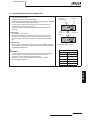 251
251
-
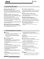 252
252
-
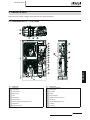 253
253
-
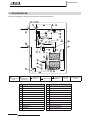 254
254
-
 255
255
-
 256
256
-
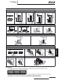 257
257
-
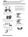 258
258
-
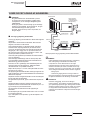 259
259
-
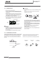 260
260
-
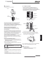 261
261
-
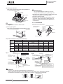 262
262
-
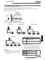 263
263
-
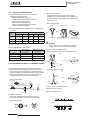 264
264
-
 265
265
-
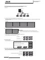 266
266
-
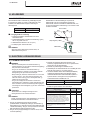 267
267
-
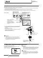 268
268
-
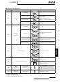 269
269
-
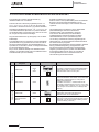 270
270
-
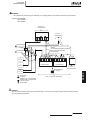 271
271
-
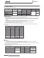 272
272
-
 273
273
-
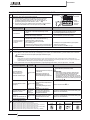 274
274
-
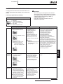 275
275
-
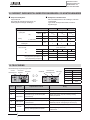 276
276
-
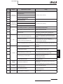 277
277
-
 278
278
-
 279
279
-
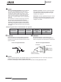 280
280
-
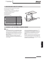 281
281
-
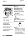 282
282
-
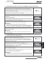 283
283
-
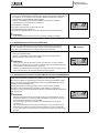 284
284
-
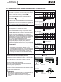 285
285
-
 286
286
-
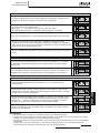 287
287
-
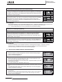 288
288
-
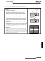 289
289
-
 290
290
-
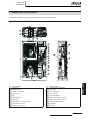 291
291
-
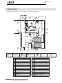 292
292
-
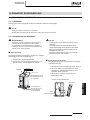 293
293
-
 294
294
-
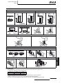 295
295
-
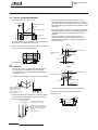 296
296
-
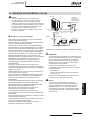 297
297
-
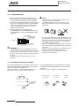 298
298
-
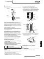 299
299
-
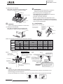 300
300
-
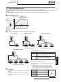 301
301
-
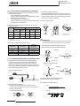 302
302
-
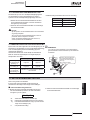 303
303
-
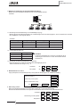 304
304
-
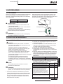 305
305
-
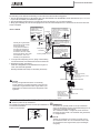 306
306
-
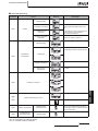 307
307
-
 308
308
-
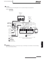 309
309
-
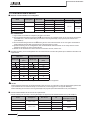 310
310
-
 311
311
-
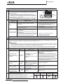 312
312
-
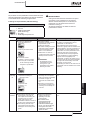 313
313
-
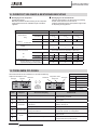 314
314
-
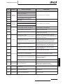 315
315
-
 316
316
-
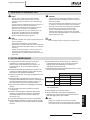 317
317
-
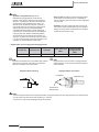 318
318
-
 319
319
-
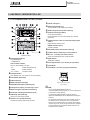 320
320
-
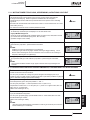 321
321
-
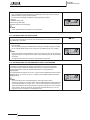 322
322
-
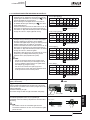 323
323
-
 324
324
-
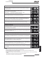 325
325
-
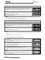 326
326
-
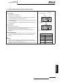 327
327
-
 328
328
-
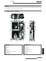 329
329
-
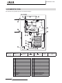 330
330
-
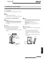 331
331
-
 332
332
-
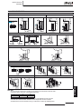 333
333
-
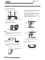 334
334
-
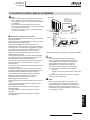 335
335
-
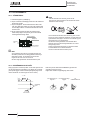 336
336
-
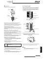 337
337
-
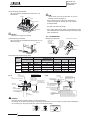 338
338
-
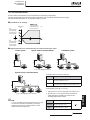 339
339
-
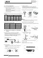 340
340
-
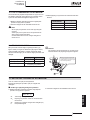 341
341
-
 342
342
-
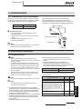 343
343
-
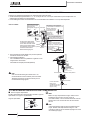 344
344
-
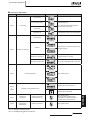 345
345
-
 346
346
-
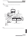 347
347
-
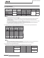 348
348
-
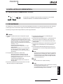 349
349
-
 350
350
-
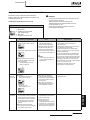 351
351
-
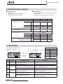 352
352
-
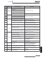 353
353
-
 354
354
-
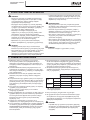 355
355
-
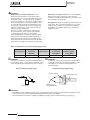 356
356
-
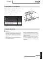 357
357
-
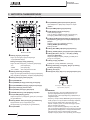 358
358
-
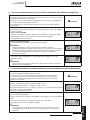 359
359
-
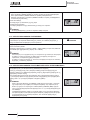 360
360
-
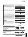 361
361
-
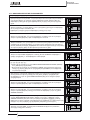 362
362
-
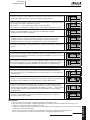 363
363
-
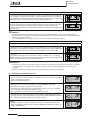 364
364
-
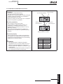 365
365
-
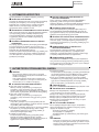 366
366
-
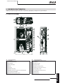 367
367
-
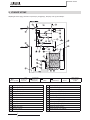 368
368
-
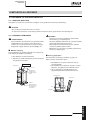 369
369
-
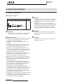 370
370
-
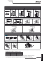 371
371
-
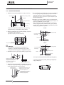 372
372
-
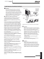 373
373
-
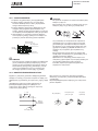 374
374
-
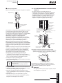 375
375
-
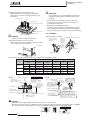 376
376
-
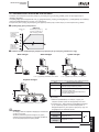 377
377
-
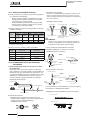 378
378
-
 379
379
-
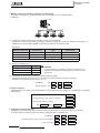 380
380
-
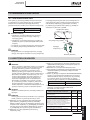 381
381
-
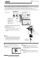 382
382
-
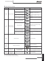 383
383
-
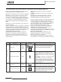 384
384
-
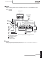 385
385
-
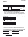 386
386
-
 387
387
-
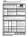 388
388
-
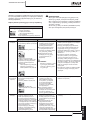 389
389
-
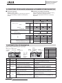 390
390
-
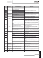 391
391
-
 392
392
-
 393
393


Hitachi HRNM/FSN(2)(M)(E) Istruzioni per l'uso
- Categoria
- Condizionatori d'aria a sistema split
- Tipo
- Istruzioni per l'uso
in altre lingue
- English: Hitachi HRNM/FSN(2)(M)(E) Operating instructions
- français: Hitachi HRNM/FSN(2)(M)(E) Mode d'emploi
- español: Hitachi HRNM/FSN(2)(M)(E) Instrucciones de operación
- Deutsch: Hitachi HRNM/FSN(2)(M)(E) Bedienungsanleitung
- Nederlands: Hitachi HRNM/FSN(2)(M)(E) Handleiding
- português: Hitachi HRNM/FSN(2)(M)(E) Instruções de operação
- dansk: Hitachi HRNM/FSN(2)(M)(E) Betjeningsvejledning
- svenska: Hitachi HRNM/FSN(2)(M)(E) Bruksanvisningar
Documenti correlati
-
Hitachi RAS-8HNPE Istruzioni per l'uso
-
Hitachi P-N23NA Istruzioni per l'uso
-
-
-
-
-
-
-
-
Altri documenti
-
McQuay 5ACV 55 CR Guida d'installazione
-
Acson IM-5ACV3-0505-ACSON Guida d'installazione
-
-
Haier 1U24GE6ERA Guida d'installazione
-
Haier 1U12BS1ERA Guida d'installazione
-
-
-
Carrier 38VBH...S Guida d'installazione
-
Castorama SCJA2519 Guida d'installazione
-
Panasonic CZANC3 Istruzioni per l'uso