
steute Technologies GmbH & Co. KG
Brückenstraße 91, 32584 Löhne, Germany, www.steute.com
1 / 16
Montage- und Anschlussanleitung / Bandschieflaufschalter
Mounting and wiring instructions / Belt alignment switch
Instructions de montage et de câblage / Interrupteur de déport de bande
Istruzioni di montaggio e collegamento / Interruttore di allineamento nastro
Instruções de montagem e instalação / Chave de desalinhamento
Инструкция по монтажу и подключению / Выключатель перекоса движения ленты
//
Ex ZS 73 SR - 3D
Nutzung der Montage- und Anschlussanleitung
Zielgruppe: autorisiertes Fachpersonal.
Sämtliche in dieser Montageanleitung beschriebenen Handhabungen
dürfen nur durch ausgebildetes und vom Anlagenbetreiber autorisier-
tes Fachpersonal durchgeführt werden.
1. Montage- und Anschlussanleitung lesen und verstehen.
2. Geltende Vorschriften über Arbeitssicherheit und Unfallverhütung
einhalten.
3. Gerät installieren und in Betrieb nehmen.
Auswahl und Einbau der Geräte sowie ihre steuerungstechnische Ein-
bindung sind an eine qualifizierte Kenntnis der einschlägigen Gesetze
und normativen Anforderungen durch den Maschinenhersteller
geknüpft.
Im Zweifelsfall ist die deutsche Sprachversion dieser
Anleitung maßgeblich.
Lieferumfang
1 Gerät, 1 Montage- und Anschlussanleitung, Kartonage.
Sicherheitshinweise
=
In diesem Dokument wird das Warndreieck zu-
sammen mit einem Signalwort verwendet, um
auf gefährliche Situationen hinzuweisen.
Die Signalwörter haben folgende Bedeutungen:
HINWEIS
zeigt eine Situation an, die einen
Sachschaden zur Folge haben
könnte.
VORSICHT
zeigt eine Situation an, die eine
geringfügige oder mäßige Ver-
letzung zur Folge haben könnte.
WARNUNG
zeigt eine Situation an, die den
Tod oder eine schwere Verlet-
zung zur Folge haben könnte.
GEFAHR
zeigt eine Situation an, die eine
schwere Verletzung oder den
Tod zur Folge hat.
Bestimmungsgemäßer Gebrauch
=
GEFAHR
Zweckentfremdete Verwendung und explosions-
fähige Einsatzumgebung. Explosionsgefahr! Ver-
brennungsgefahr! Darf nicht in Kategorien 1 und 2/
Zonen 0 und 1 und Zonen 20 und 21 eingesetzt wer-
den. Nur in zulässigen Kategorien/Zonen einsetzen.
Gerät nur entsprechend der in dieser Montage- und
Anschlussanleitung festgelegten Betriebsbedin-
gungen verwenden. Gerät nur entsprechend dem in
dieser Montage- und Anschlussanleitung genann-
ten Einsatzzweck verwenden.
Deutsch (Originalbetriebsanleitung)
Das Gerät entspricht den Europäischen Normen für den Explosions-
schutz EN 60079-0 und -31. Es ist für den Einsatz in explosionsgefähr-
deten Bereichen der Zone 22 nach EN 60079-14 vorgesehen. Die An-
forderungen der EN 60079-14, z.B. in Bezug auf Staubablagerungen
und Temperaturgrenzen, einhalten. Das Gerät ist für den Einsatz in der
Fördertechnik geeignet. Es wird zum Beispiel beidseitig an einem För-
derband montiert, um den Schieflauf des Förderbandes zu überwa-
chen. Das Gerät wird beim Herauslaufen des Förderbandes betätigt.
Dieses Signal kann je nach Ausstattung der Anlage zur Abschaltung
der Anlage oder zur Einleitung einer automatischen Bandkorrektur
sowie zusätzlich zur Auslösung optischer oder akustischer Melde-
bzw. Warnsignale führen. Das Gerät verfügt über zwangsöffnende Öff-
nerkontakte und wahlweise über eine mechanische Verriegelung. Bei
Betätigung des Geräts öffnen die Öffnerkontakte und verriegeln me-
chanisch. Zur Entriegelung verfügt das Gerät mit Verriegelung über
eine Hebelelentriegelung. Das verhindert einen unbeabsichtigten au-
tomatischen Wiederanlauf des Förderbandes.
Besondere Bedingungen und »X«-Kennzeichnung
- Anschlussleitung fest verlegen und vor mechanischer Beschädigung
hinreichend geschützt errichten.
- Anschlussleitung des Geräts in einem Gehäuse anschließen, das den
Anforderungen einer anerkannten Zündschutzart nach EN 60079-0,
Abschnitt 1, entspricht, wenn der Anschluss im explosionsgefährde-
ten Bereich liegt.
Installation, Montage und Demontage
=
GEFAHR
Spannungsführende Teile und explosionsfähige At-
mosphäre. Stromschlaggefahr! Explosionsgefahr!
Gerät vor der Inbetriebnahme auf korrekte Installa-
tion prüfen. Nationale Bestimmungen einhalten.
=
GEFAHR
Spannungsführende Teile. Explosionsfähige Atmo-
sphäre. Stromschlaggefahr! Verbrennungsgefahr!
Anschluss und Abklemmen nur durch qualifiziertes
und autorisiertes Fachpersonal. Anschluss und Ab-
klemmen nur in nicht-explosionsfähiger
Umgebung.
Bandschieflaufschalter beidseitig am Förderband in der Nähe der Um-
kehr- und Antriebstrommeln montieren. Bei sehr langen Förderbän-
dern weitere Bandschieflaufschalter montieren.
Verwendung und Betrieb
- Gerät nur innerhalb der zulässigen elektrischen Belastungsgrenzen
betreiben (siehe Technische Daten).
- Für Kurzschlussschutz Sicherungsgröße 6 A (gG/gN) verwenden.
- Gerät nur innerhalb der zulässigen Umgebungstemperaturbereiche
verwenden (siehe Typenschild und Technische Daten).
- Zur Vermeidung elektrostatischer Aufladung: Gerät über die Anbrin-
gung bzw. Befestigung oder den äußeren Erdungsanschluss in den
Potentialausgleich (Erdung) einbeziehen.

steute Technologies GmbH & Co. KG
Brückenstraße 91, 32584 Löhne, Germany, www.steute.com
2 / 16
Montage- und Anschlussanleitung / Bandschieflaufschalter
Mounting and wiring instructions / Belt alignment switch
Instructions de montage et de câblage / Interrupteur de déport de bande
Istruzioni di montaggio e collegamento / Interruttore di allineamento nastro
Instruções de montagem e instalação / Chave de desalinhamento
Инструкция по монтажу и подключению / Выключатель перекоса движения ленты
//
Ex ZS 73 SR - 3D
English
Use of the mounting and wiring instructions
Target group: authorised and qualified staff.
All actions described in these instructions may only be performed by
qualified persons who have been trained and authorised by the
operating company.
1. Read and understand these mounting and wiring instructions.
2. Comply with the valid occupational safety and accident prevention
regulations.
3. Install and operate the device.
Selection and installation of devices and their integration in control
systems demand qualified knowledge of all the relevant laws, as well
as the normative requirements of the machine manufacturer.
In case of doubt, the German language version of these instructions
shall prevail.
Scope of delivery
1 device, 1 mounting and wiring instructions, carton.
Safety information
=
In this document, the warning triangle is used
together with a signal word to indicate a
hazardous situation.
The signal words have the following meanings:
NOTICE
indicates a situation which may
result in material damage.
CAUTION
indicates a situation which may
result in minor or moderate
injury.
WARNING
indicates a situation which may
result in serious injury or death.
DANGER
indicates a situation which will
result in serious injury or death.
Intended use
=
DANGER
Misuse and explosive environment. Explosion
hazard! Risk of burns! Not for use in categories 1
and 2/zones 0 and 1 and zones 20 and 21. Use only
in permitted categories/zones. Use device only in
accordance with the operating conditions defined
in the mounting and wiring instructions. Use device
only in accordance with the intended purpose de-
fined in the mounting and wiring instructions.
The device complies with the European standards for explosion protec-
tion EN 60079-0 and -31. It is intended for use in hazardous areas of
zone 22 according to EN 60079-14. Comply with the requirements of
EN 60079-14, e.g. with regard to dust deposits and temperature limits.
Deutsch (Originalbetriebsanleitung)
Reinigung
- Zur Vermeidung elektrostatischer Aufladung darf das Gerät in
explosionsgefährdeten Bereichen nur mit einem feuchten Tuch
gereinigt werden.
- Bei feuchter Reinigung: Wasser oder milde, nicht-scheuernde,
nicht-kratzende Reinigungsmittel verwenden.
- Keine aggressiven Reinigungs- oder Lösungsmittel verwenden.
Instandhaltung, Wartung und Reparatur
=
GEFAHR
Spannungsführende Teile. Explosionsfähige Atmo-
sphäre. Stromschlaggefahr! Explosionsgefahr!
Verbrennungsgefahr! Beschädigte und defekte Ge-
räte nicht reparieren, sondern ersetzen. Umbauten
und Veränderungen am Gerät unterlassen.
Bei sorgfältiger Montage, unter der Beachtung der oben beschriebe-
nen Hinweise, ist nur eine geringe Wartung notwendig. Wir empfehlen
eine regelmäßige Wartung wie folgt:
1. Prüfen der Seilzugfunktion.
2. Entfernen von Schmutz.
3. Prüfen der Leitungseinführung und -anschlüsse.
Entsorgung
- Nationale, lokale und gesetzliche Bestimmungen zur
Entsorgung beachten.
- Materialien getrennt dem Recycling zuführen.
Hinweise
Die Gebrauchslage ist beliebig. Umbauten und Veränderungen am
Gerät, die den Explosionsschutz beeinträchtigen, sind nicht gestattet.
Für das Errichten von elektrischen Betriebsmitteln in explosionsge-
fährdeten Bereichen gilt die EN 60079-14. Zu beachten sind zudem die
ATEX-Prüfbescheinigung und die darin enthaltenen besonderen Be-
dingungen. Ein komplettes sicherheitsgerichtetes System enthält in
der Regel Sensoren, Auswerteeinheiten, Meldegeräte und Konzepte
für sichere Abschaltungen. Für die Verschaltung des Geräts in das Ge-
samtsystem muss die in der Risikoanalyse festgelegte Steuerungska-
tegorie durchgehend eingehalten werden. Hierzu ist auch eine Validie-
rung nach EN ISO 13849-2 bzw. nach EN 62061 erforderlich. Desweite-
ren kann der Performance-Level nach EN ISO 13849-1 bzw. SIL-CL-
Level nach EN 62061 durch Verkettung von mehreren Sicherheitsbau-
teilen und anderen sicherheitsgerichteten Geräten, z.B. Reihenschal-
tung von Sensoren, niedriger ausfallen als die Einzellevel. Es liegt im
Verantwortungsbereich des Herstellers einer Anlage oder Maschine,
die korrekte Gesamtfunktion sicherzustellen. Technische Änderungen
vorbehalten.

steute Technologies GmbH & Co. KG
Brückenstraße 91, 32584 Löhne, Germany, www.steute.com
3 / 16
Montage- und Anschlussanleitung / Bandschieflaufschalter
Mounting and wiring instructions / Belt alignment switch
Instructions de montage et de câblage / Interrupteur de déport de bande
Istruzioni di montaggio e collegamento / Interruttore di allineamento nastro
Instruções de montagem e instalação / Chave de desalinhamento
Инструкция по монтажу и подключению / Выключатель перекоса движения ленты
//
Ex ZS 73 SR - 3D
English
The device is suitable for applications with conveyor technology. It is
installed e.g. on both sides of a conveyor belt in order to monitor mis-
alignment of the belt. The device is actuated upon movement of the
conveyor belt. This signal can either switch off the system or start an
automatic belt position correction, as well as, at the same time, gener-
ate an optical or acoustic indicating or warning signal. The device has
positive break NC contacts and, as an option, mechanical latching.
Upon actuation, the NC contacts are opened and latched mechanically.
The release can be carried out by a lever. This prevents an unintention-
al, automatic restart of the conveyor belt.
Special conditions and »X« marking
- The device's connection cables must have a fixed installation and be
set up in a manner that protects them from mechanical damages.
- If the connection is in an explosive area, the connection cable has to
be connected in an enclosure which complies with the requirements
of an approved ignition protection degree according to EN 60079-0,
par. 1.
Installation, mounting and dismantling
=
DANGER
Live parts and explosive atmosphere. Electric
shock hazard! Explosion hazard! Before commis-
sioning, check device for correct installation. Com-
ply with national regulations.
=
DANGER
Live parts. Explosive atmosphere.
Electric shock
hazard! Risk of burns! Connecting and disconnect-
ing only to be performed by qualified and author-
ised personnel. Connecting and disconnecting only
in non-explosive environment.
Install the belt alignment switch at both sides of the conveyor belt
close to the deflection and drive pulleys. In the case of very long con-
veyor systems, install additional belt alignment switches.
Application and operation
- Use device only within the permitted electrical load limits
(see technical data).
- For short-circuit protection, use fuse size 6 A (gG/gN).
- Use device only within the permitted ambient temperature range
(see product label and technical data).
- To prevent electrostatic charge: Include the device in the equipoten-
tial bonding (earthing) via the mounting or bracket or the external
earthing connection.
Cleaning
- Use a damp cloth to clean devices in explosive areas. This prevents
electrostatic charge.
- In case of damp cleaning: Use water or mild, non-scratching,
non-chafing cleaners.
- Do not use aggressive cleaners or solvents.
Maintenance, service and repair
=
DANGER
Live parts. Explosive atmosphere. Electric shock
hazard! Explosion hazard! Risk of burns! Do not
repair defective or damaged devices. Replace them.
Do not rebuild or modify the device in any way.
With careful mounting as described above, only minor maintenance is
necessary. We recommend a routine maintenance as follows:
1. Check pull-wire function.
2. Remove all dirt.
3. Check sealing of the cable or conduit connections.
Disposal
- Observe national, local and legal regulations concerning disposal.
- Recycle each material separately.
N.B.
Any mounting position is possible. Reconstruction and alterations to
the device which might affect the explosion protection are not allowed.
Furthermore, EN 60079-14 has to be applied for the installation of
electrical equipment in explosive areas. Moreover, the ATEX test certif-
icate and the special conditions therein have to be observed. A com-
plete safety system normally covers sensors, monitoring modules, in-
dicator switches and concepts for safe disconnection. For integration
of the device in the entire system, strictly observe and respect the con-
trol category determined in the risk assessment. Therefore, a valida-
tion according to EN ISO 13849-2 or EN 62061 is necessary. Further-
more, the Performance Level according to EN ISO 13849-1 and SIL CL
Level according to EN 62061 can be lower than the single level be-
cause of the combination of several safety components and other
safety-related devices, e.g. by serial connection of sensors. It is the
responsibility of the manufacturer of a plant or machine to guarantee
the correct general function. Subject to technical modifications.
Français
Utilisation des instructions de montage et de câblage
Groupe cible: personnel autorisé et compétent.
Toutes les manipulations décrites dans cette notice d‘installation ne
doivent être effectuées que par du personnel formé et autorisé par la
société exploitante.
1. Lire et comprendre les instructions de montage et de câblage.
2. Respecter les règles de sécurité et de prévention des accidents en
vigueur.
3. Installer l’appareil et le mettre en service.
La sélection et l'installation des appareils et leurs intégrations dans
les systèmes de commande exigent une connaissance approfondie

steute Technologies GmbH & Co. KG
Brückenstraße 91, 32584 Löhne, Germany, www.steute.com
4 / 16
Montage- und Anschlussanleitung / Bandschieflaufschalter
Mounting and wiring instructions / Belt alignment switch
Instructions de montage et de câblage / Interrupteur de déport de bande
Istruzioni di montaggio e collegamento / Interruttore di allineamento nastro
Instruções de montagem e instalação / Chave de desalinhamento
Инструкция по монтажу и подключению / Выключатель перекоса движения ленты
//
Ex ZS 73 SR - 3D
de toutes les lois pertinentes, ainsi que des exigences normatives du
fabricant de la machine.
En cas de doute, la version allemande fait référence.
Volume de livraison
1 appareil, 1 instruction de montage et de câblage, carton.
Instructions de sécurité
=
Dans ce document, le triangle de présignalisa-
tion est utilisé avec un mot-clé pour signaler
les situations dangereuses.
Les mots-clés ont les significations suivantes:
NOTICE
indique une situation qui pour-
rait entraîner un dommage
matériel.
ATTENTION
indique une situation qui pour-
rait entraîner une blessure
légère ou gravité modérée.
MISE EN GARDE
indique une situation qui pour-
rait entraîner la mort ou une
blessure grave.
DANGER
indique une situation qui en-
traîne une blessure grave ou
la mort.
Utilisation conforme
=
DANGER
D’utilisations non conformes et un environnement
potentiellement explosif. Risque d'explosion!
Risque de brûlure! Ne doit pas être utilisé dans
les catégories 1 et 2/zones 0 et 1 et zones 20 et 21.
Utiliser uniquement dans les catégories/zones au-
torisées. N’utiliser l’appareil qu’en conformité avec
les conditions de fonctionnement stipulées dans
ces instructions de montage et de câblage. Utiliser
uniquement en conformité avec les applications sti-
pulées dans ces instructions de montage et
de câblage.
L’appareil répond aux normes Européennes pour la protection contre
les explosions EN 60079-0 et -31. Il est prévu pour l'utilisation en envi-
ronnements à risque d'explosion de la zone 22 selon EN 60079-14. Ob-
server les exigences de EN 60079-14, par ex. en rapport avec les dé-
pôts de poussières et limites de températures. L’appareil est approprié
pour l'utilisation dans la technique de convoyage. Il est monté, par
exemple, sur les deux côtés d’une bande transporteuse pour surveiller
le désalignement de la bande. L’appareil est actionné si la bande
transporteuse sort de son axe. Selon l’équipement de l’installation, ce
signal peut amener à l’arrêt du système ou démarrer une correction
automatique de la bande, tout comme déclencher des signaux
d’alarme ou de signalisation acoustiques ou optiques. L’appareil dis-
pose des contacts NF à guidage forcé et, en option, d’un verrouillage
Français
mécanique. En actionnant l’appareil, les contacts NF s’ouvrent et se
verrouillent mécaniquement. Pour le déverrouillage, l’appareil avec
verrouillage dispose d’un déverrouillage par levier. De cette façon, un
redémarrage involontaire automatique de la bande transporteuse est
évité.
Conditions particulières et marquage »X«
- Poser et fixer le câble de raccordement et le protéger suffisamment
contre tout dommage mécanique.
- Brancher le câble de raccordement de l’appareil dans un boîtier qui
répond aux exigences d'un mode de protection reconnu selon EN
60079-0, alinéa 1, si la connexion se trouve dans un environnement
potentiellement explosif.
Installation, montage et démontage
=
DANGER
Pièces sous tension et atmosphère potentiellement
explosive. Risque d’électrocution! Risque d'explo-
sion! Contrôler l’installation correcte de l’appareil
avant sa mise en service. Se conformer aux dispo-
sitions en vigueur dans le pays.
=
DANGER
Pièces sous tension. Atmosphère potentiellement
explosive. Risque d’électrocution! Risque de brû-
lure! Raccordement et débranchement que par du
personnel qualifié et autorisé. Raccordement et dé-
branchement uniquement dans un environnement
non explosif.
Monter les interrupteurs de déport de bande sur les deux côtés de la
bande transporteuse à proximité de la poulie de renvoi et le du tam-
bour d’entraînement. Pour des bandes transporteuses plus longues
monter des interrupteurs de déport de bande supplémentaires.
Utilisation et opération
- N’utiliser l’appareil que dans les limites des charges électriques au-
torísées (voir données techniques).
- Pour la protection contre les courts-circuits, utiliser un fusible de
6 A (gG/gN).
- N’utiliser l’appareil que dans la plage de température ambiante au-
torisée (voir plaque d’identification et données techniques).
- Pour éviter les charges électrostatiques: Intégrer l'appareil dans la
liaison équipotentielle (mise à la terre) via l'attache ou la fixation ou
bien la connexion à la terre externe.
Nettoyage
- Pour éviter une charge électrostatique, l’appareil ne doit être nettoyé
qu’avec un chiffon humide dans des environnements
potentiellement explosifs.
- Pour un nettoyage humide: utiliser de l’eau ou un nettoyant doux,
non abrasif, qui ne raye pas.
- Ne pas utiliser de nettoyants ou solvants agressifs.

steute Technologies GmbH & Co. KG
Brückenstraße 91, 32584 Löhne, Germany, www.steute.com
5 / 16
Montage- und Anschlussanleitung / Bandschieflaufschalter
Mounting and wiring instructions / Belt alignment switch
Instructions de montage et de câblage / Interrupteur de déport de bande
Istruzioni di montaggio e collegamento / Interruttore di allineamento nastro
Instruções de montagem e instalação / Chave de desalinhamento
Инструкция по монтажу и подключению / Выключатель перекоса движения ленты
//
Ex ZS 73 SR - 3D
Italiano
Utilizzo delle istruzioni di montaggio e collegamento
Gruppo target: personale autorizzato e qualificato.
Tutte le azioni descritte nelle presenti istruzioni possono essere ese-
guite esclusivamente da personale qualificato, addestrato e autorizza-
to dall’azienda di gestione.
1. Leggere e comprendere le presenti istruzioni di montaggio e colle-
gamento.
2. Rispettare le norme vigenti in materia di sicurezza sul lavoro e pre-
venzione dagli infortuni.
3. Installare e mettere in funzione il dispositivo.
Français
Maintenance, entretien et réparation
=
DANGER
Pièces sous tension. Atmosphère potentiellement
explosive. Risque d‘électrocution! Risque d’ex-
plosion! Risque de brûlure! Ne pas réparer les
appareils endommagés ou défectueux, mais les
remplacer. S’abstenir de faire des modifications ou
changements de l’appareil.
Avec une installation soignée et en respectant les indications décrites
ci-dessus, seul un entretien minimal est nécessaire:
1. Contrôler la fonction de traction du câble.
2. Enlever les salissures.
3. Contrôler les entrées de câble et les raccordements.
Elimination des déchets
- Observer les dispositions nationales, locales et légales pour
l‘élimination.
- Trier les déchets pour le recyclage.
Remarques
La position de montage est indifférente. Des transformations et modi-
fications de l'appareil qui altèrent la protection contre les explosions
ne sont pas autorisées. L'installation d'équipements électriques dans
des atmosphères potentiellement explosives est soumise à la norme
EN 60079-14. Il faut également observer le certificat d'essai ATEX et
les conditions particulières qui y figurent. Un système de sécurité se
compose généralement de multiples capteurs, modules de sécurité,
dispositifs de signalisation et concepts assurant un déclenchement
sûr. Pour le câblage de l'appareil dans le système entier, la catégorie
déterminée dans l’analyse des risques est à observer et à respecter
strictement. Pour ce faire, une validation selon EN ISO 13849-2 ou
selon EN 62061 est nécessaire. De plus, le niveau de perfomance PL
selon EN ISO 13849-1 ou niveau d’intégrité de sécurité SIL selon EN
62061 peut être inférieur au niveau des composant de sécurité pris
individuellement, dans le cas d’une mise-en-série, par exemple. Le
constructeur d’une machine ou installation doit assurer le fonctionne-
ment de l’ensemble. Sous réserve de modifications techniques.
La scelta e l’installazione dei dispositivi e la loro integrazione nei siste-
mi di controllo richiedono una conoscenza specifica di tutte le relative
leggi e dei requisiti normativi del costruttore della macchina.
In caso di dubbi, fa fede la versione in lingua tedesca di
queste istruzioni.
Fornito con il prodotto
1 dispositivo, 1 istruzioni di montaggio e collegamento, imballo.
Informazioni di sicurezza
=
In questo documento, il triangolo di emergenza
viene utilizzato insieme a una parola di segna-
lazione per indicare una situazione pericolosa.
Le parole di segnalazione hanno i seguenti significati:
AVVISO
indica una situazione che può
causare danni materiali.
ATTENZIONE
indica una situazione che può
causare lesioni lievi o moderate.
AVVERTIMENTO
indica una situazione che può
causare lesioni gravi o morte.
PERICOLO
indica una situazione che causa
lesioni gravi o morte.
Destinazione d‘uso
=
PERICOLO
Uso improprio ed ambiente esplosivo. Pericolo di
esplosione! Rischio di ustione! Non deve essere
utilizzato in categorie 1 e 2/zone 0 e 1 e zone 20
e 21. Utilizzare esclusivamente nelle categorie/
zone consentite. Utilizzare il dispositivo soltanto in
conformità con le condizioni operative definite nelle
istruzioni di montaggio e collegamento. Utilizzare il
dispositivo soltanto ai fini definiti nelle istruzioni di
montaggio e collegamento.
Il dispositivo è conforme agli standard europei per la protezione dalle
esplosioni EN 60079-0 e -31. È destinato all‘uso in aree pericolose
della zona 22 secondo EN 60079-14. Rispettare i requisiti della EN
60079-14, ad es. per quanto riguarda i depositi di polvere e i limiti di
temperatura. Il dispositivo è adatto per applicazioni nel campo della
movimentazione dei materiali. Ad esempio viene montato su entrambi
i lati di un nastro trasportatore per controllare il mancato allineamen-
to del nastro stesso. Il dispositivo si aziona nel momento in cui il na-
stro trasportatore esce dalla propria traiettoria. Il segnale, a seconda
dell’impostazione aziendale, può portare allo spegnimento dell’im-
pianto oppure alla correzione automatica dell’allineamento del nastro,
nonché a far scaturire segnali di allarme e d’emergenza ottici e acu-
stici. Il dispositivo è dotato di contatti NC ad apertura obbligata e, a ri-
chiesta, di un blocco meccanico. Azionando il dispositivo, i contatti NC
si aprono e si bloccano meccanicamente. Per lo sblocco, il dispositivo
con blocco dispone di una leva apposita. In questo modo viene impedi-
ta una ripartenza automatica involontaria del nastro trasportatore.

steute Technologies GmbH & Co. KG
Brückenstraße 91, 32584 Löhne, Germany, www.steute.com
6 / 16
Montage- und Anschlussanleitung / Bandschieflaufschalter
Mounting and wiring instructions / Belt alignment switch
Instructions de montage et de câblage / Interrupteur de déport de bande
Istruzioni di montaggio e collegamento / Interruttore di allineamento nastro
Instruções de montagem e instalação / Chave de desalinhamento
Инструкция по монтажу и подключению / Выключатель перекоса движения ленты
//
Ex ZS 73 SR - 3D
Italiano
Condizioni speciali e marcatura »X«
- Il cavo di collegamento deve essere fissato e posizionato in modo che
sia protetto da danni meccanici.
- Se il collegamento viene effettuato all’interno di un ambiente a ri-
schio di esplosione, collegare il cavo in un alloggiamento che soddisfi
i requisiti di un tipo riconosciuto di protezione antideflagrante secon-
do EN 60079-0.
Installazione, montaggio e smontaggio
=
PERICOLO
Componenti sotto tensione ed atmosfere esplosive.
Pericolo di scossa elettrica! Pericolo di esplosione!
Prima della messa in funzione, verificare che il di-
spositivo sia stato installato correttamente. Osser-
vare le disposizioni nazionali.
=
PERICOLO
Componenti sotto tensione. Atmosfera esplosiva.
Pericolo di scossa elettrica! Rischio di ustione!
Connessione e disconnessione soltanto da parte di
personale qualificato ed autorizzato. Connessione
e disconnessione soltanto in ambienti non esplosivi.
Per questo motivo, l’interruttore di allineamento nastro dovrebbe es-
sere installato ad entrambe le estremità del nastro trasportatore in
prossimità dei deflettori e delle pulegge. Nel caso di nastri trasporta-
tori molto lunghi, è necessario installare degli interruttori di allinea-
mento supplementari.
Uso e funzionamento
- Utilizzare il dispositivo soltanto entro i limiti di carico elettrico con-
sentiti (vedere i dati tecnici).
- Per la protezione da cortocircuito, utilizzare fusibili di dimensione
6 A (gG/gN).
- Utilizzare il dispositivo soltanto entro il range di temperature con-
sentito (vedere l’etichetta del prodotto e i dati tecnici).
- Per prevenire la carica elettrostatica: Includere il dispositivo nel col-
legamento (messa a terra) tramite il montaggio di staffa o connessio-
ne di terra esterna.
Pulizia
- Utilizzare un panno umido per pulire dispositivi in aree esplosive.
In questo modo si impedisce la carica elettrostatica.
- Per la pulizia a umido: utilizzare acqua oppure detergenti delicati,
non abrasivi, non graffianti.
- Non utilizzare detergenti o solventi aggressivi.
Manutenzione, assistenza e riparazione
=
PERICOLO
Componenti sotto tensione. Atmosfera esplosiva.
Pericolo di scossa elettrica! Pericolo di esplosione!
Rischio di ustione! Non tentare di riparare disposi-
tivi difettosi e danneggiati. Sostituirli. Non trasfor-
mare o modificare il dispositivo.
Con un montaggio attento come sopra descritto, si necessiterà di
poche operazioni di manutenzione. Suggeriamo una manutenzione
regolare seguendo i seguenti passi:
1. Controllare la funzione di trazione del cavo.
2. Rimuovere tutta la sporcizia.
3. Verificare le entrare e i collegamenti dei cavi.
Smaltimento
- Osservare le norme nazionali, locali e legali per lo smaltimento.
- Riciclare ciascun materiale separatamente.
Indicazioni
Ogni posizione di montaggio è possibile. Non sono consentite altera-
zioni e modifiche al dispositivo, che compromettano la protezione anti-
deflagrante. Per la costruzione di apparecchiature elettriche in aree a
rischio di esplosione si applica la EN 60079-14. Occorre inoltre osser-
vare il certificato di prova ATEX e le particolari condizioni in esso con-
tenute. Di norma un completo sistema di sicurezza comprende senso-
ri, unità di valorizzazione, apparecchi di segnalazione nonché sistemi
per uno spegnimento sicuro. Per collegare il dispositivo nel sistema
globale, deve essere mantenuta la categoria di controllo definita
nell’analisi del rischio. A tal fine è richiesta anche una convalida se-
condo EN ISO 13849-2 oppure EN 62061. Inoltre, il Performance Level
secondo EN ISO 13849-1 e SIL CL Level secondo EN 62061 può essere
inferiore rispetto al singolo livello, a causa della combinazione di di-
versi componenti di sicurezza ed altri dispositivi di sicurezza, come ad
esempio il collegamento in serie di sensori. Il produttore di un im-
pianto o macchinario si assume la responsabilità della sua corretta
funzione globale. Soggetta a modifiche tecniche.
Português
Utilização das instruções de montagem e instalação
Público alvo: pessoal autorizado e qualificado.
Todas as ações descritas neste manual somente podem ser realizadas
por pessoal qualificado, os quais tenham sido treinados e autorizados
pela empresa.
1. Ler e compreender estas instruções de montagem e instalação.
2. Seguir as normas e regulamentos válidos para segurança ocupacio-
nal e prevenção de acidentes.
3. Instalar e operar o dispositivo.
Seleção e instalação dos dispositivos e sua intregração no sistema de
controle demanda conhecimento qualificado de todas as leis relevan-
tes, assim como dos requerimentos norminativos do fabricante
da máquina.

steute Technologies GmbH & Co. KG
Brückenstraße 91, 32584 Löhne, Germany, www.steute.com
7 / 16
Montage- und Anschlussanleitung / Bandschieflaufschalter
Mounting and wiring instructions / Belt alignment switch
Instructions de montage et de câblage / Interrupteur de déport de bande
Istruzioni di montaggio e collegamento / Interruttore di allineamento nastro
Instruções de montagem e instalação / Chave de desalinhamento
Инструкция по монтажу и подключению / Выключатель перекоса движения ленты
//
Ex ZS 73 SR - 3D
Português
No caso de dúvidas, prevalecerá a versão em alemão
dessas instruções.
Escopo de entrega
1 dispositivo, 1 instruções de montagem e instalação, caixa
em papelão.
Informações de segurança
=
Neste documento, o triângulo de advertência
é usado com uma palavra para indicação de
situação perigosa.
As palavras possuem os seguintes significados:
AVISO
indica uma situação que pode
resultar em danos materiais.
CUIDADO
indica uma situação que pode
resultar em lesão mínima ou
moderada.
ATENÇÃO
indica uma situação que pode
resultar em lesão grave ou
morte.
PERIGO
indica uma situação que resul-
tará em lesão grave ou morte.
Uso pretendido
=
PERIGO
Má utilização e ambiente explosivo. Perigo de
explosão! Risco de queimaduras! Não deve ser
utilizado na categorias 1 e 2/zonas 0 e 1 e zonas 20
e 21. Use apenas em categorias/zonas permitidas.
Use o dispositivo apenas nas condições opera-
cionais definidas nas instruções de montagem e
instalação. Use o dispositivo apenas na finalidade
pretendida definida nas instruções de montagem
e instalação.
O dispositivo está em conformidade com as normas européias para
proteção contra explosão EN 60079-0 e -31. O dispositivo destina-se
para utilização em áreas classificadas como zona 22 de acordo com a
EN 60079-14. Atende aos requisitos da EN 60079-14, por ex. no que diz
respeito a acumulo de poeira e limites de temperatura. O dispositivo é
adequado para aplicação em esteiras transportadoras. Por exemplo, é
montado em ambos os lados de uma correia de transporte para moni-
torizar o desvio da mesma. O dispositivo é acionado com o movimento
da correia de transporte. Dependendo do escopo escolhido a chave li-
bera um sinal que provoca o desligamento do equipamento, ou então,
inicializa o processo automático de realinhamento, além de liberar a
sinalização de advertência visual. O dispositivo possui contatos NF
com ruptura positiva e, opcionalmente, travamento mecânico. No mo-
mento da atuação do dispositivo os contatos NF abrem e executam o
bloqueio mecânico. Para destravar os dispositivos destinadas a áreas
vem equipadas com um braço de desbloqueio. Assim se evita um reli-
gamento automático e involuntário da esteira.
Condições especiais e marcação »X«
- Os cabos de conexão do dispositivo devem ter uma instalação fixa e
protegidos contra danos mecânicos.
- Caso a ligação seja realizada em uma atmosfera explosiva, o cabo de
conexão deve ser conectado em invólucro em conformidade com as
exigências de um tipo de proteção contra ignição, aprovado de acordo
com a norma EN 60079-0, par. 1.
Instalação, montagem e desmontagem
=
PERIGO
Partes vivas e atmosfera explosiva. Risco de cho-
que elétrico! Perigo de explosão! Antes de posicio-
nar, cheque o dispositivo para instalação correta.
Obedecer às normas nacionais.
=
PERIGO
Partes vivas. Atmosferas explosivas. Risco de cho-
que elétrico! Risco de queimaduras! Conexão e
desconexão apenas por pessoal qualificado e auto-
rizado. Conexão e desconexão apenas em ambiente
não explosivo.
A recomendação é de que as chaves de desalinhamento sejam mon-
tadas em ambos os lados da esteira, nas proximidades das polias de
acionamento e reversão. Nos casos de esteiras longas é razoável a
instalação intermediária destas chaves.
Aplicação e operação
- Use o dispositivo somente dentro dos limites de carga elétrica auto-
rizada (ver dados técnicos).
- Para proteção de curto-circuito utilizar fusível 6 A (gG/gN).
- Use o dispositivo somente dentro do intervalo de temperatura am-
biente permitido (ver rótulo do produto e dados técnicos).
- Para evitar carga eletrostática: Inclua o dispositivo na ligação equi-
potencial (aterramento) através da montagem, do suporte ou da co-
nexão de aterramento externa.
Limpeza
- Use um pano úmido para limpar dispositivos em áreas explosivas.
Isto previne contra carga eletrostática.
- Em caso de limpeza úmida: Use água e produtos de limpeza
não abrasivos.
- Não utilize produtos de limpeza agressivos e solventes.

steute Technologies GmbH & Co. KG
Brückenstraße 91, 32584 Löhne, Germany, www.steute.com
8 / 16
Montage- und Anschlussanleitung / Bandschieflaufschalter
Mounting and wiring instructions / Belt alignment switch
Instructions de montage et de câblage / Interrupteur de déport de bande
Istruzioni di montaggio e collegamento / Interruttore di allineamento nastro
Instruções de montagem e instalação / Chave de desalinhamento
Инструкция по монтажу и подключению / Выключатель перекоса движения ленты
//
Ex ZS 73 SR - 3D
Русский
Использование Инструкции по монтажу и подключению
Целевая группа: специально уполномоченный персонал.
Все операции, описанные в данном руководстве по монтажу, долж-
ны выполняться только квалифицированным персоналом, уполно-
моченным эксплуатационником оборудования.
1. Прочитать и понять Инструкция по монтажу и подключению.
2. Соблюдать действующие предписания по технике безопасности и
предотвращению несчастных случаев.
3. Установка и ввод устройства в эксплуатацию.
Выбор и установка устройств, а также их интеграция в системы
управления связаны с квалифицированными знаниями соответ-
Português
Manutenção, serviços, reparo
=
PERIGO
Partes vivas. Atmosferas explosivas. Risco de cho-
que elétrico! Perigo de explosão! Risco de queima-
duras! Não repare dispositivos com defeito e danos.
Substitua. Não reconstruir ou alterar o dispositivo.
Com a montagem feita de maneira cuidadosa como descrito acima,
apenas pequenas manutenções serão necessárias. Recomendamos
a manutenção de rotina da seguinte forma:
1. Verifique a função de tração.
2. Remover toda sujeira.
3. Verificar o estado da vedação do prensa cabos.
Descarte
- Observe as disposições legais locais a referente ao descarte.
- Separar materiais recicláveis.
Observações
O posicionamento de uso é livre. Modificações e alterações no disposi-
tivo – as quais possa afetar a proteção contra explosão – não são per-
mitidas. Além disso, a EN 60079-14 (ABNT NBR IEC 60079-14) tem que
ser aplicada para a instalação de equipamentos elétricos em atmosfe-
ras explosivas. Além disso, o certificado de conformidade ATEX tem
que ser observado. Um completo sistema de segurança normalmente
abrange os sensores, módulos de monitoramento e chaves indicado-
ras para um desconexão segura. Para integração do dispositivo no sis-
tema completo, a categoria de determinada na avaliação de risco tem
que ser estritamente observada e respeitada. Além disso, é necessária
validação conforme EN ISO 13849-2 ou EN 62061. Além disto o Perfor-
mance Level conforme EN ISO 13849-1 ou SIL CL Level conforme EN
62061 pode ser reduzido quando encadeados diversos componentes
de segurança ou outros dispositivos relacionados a segurança, como
por exemplo conectando diversos sensores em série. É de responsa-
bilidade do fabricante da instalação ou máquina assegurar o perfeito
funcionamento de todas as funções. Sujeito a alterações técnicas.
ствующих законов и нормативных требований производителя
оборудования.
В случае сомнения версия на немецком языке
является определяющей.
Комплект поставки
1 устройство, 1 инструкция по монтажу и подключению, картонаж.
Указания по безопасности
=
В этом документе используется предупрежда-
ющий треугольник вместе с сигнальным сло-
вом, чтобы указывать на опасные ситуации.
Сигнальные слова имеют следующие значения:
УВЕДОМЛЕНИЕ
показывает ситуацию, след-
ствием которой может быть
материальный ущерб.
ВНИМАНИЕ
показывает ситуацию, след-
ствием которой может быть
небольшая или умеренная
травма.
ПРЕДУПРЕЖДЕНИЕ
показывает ситуацию, след-
ствием которой может быть
смерть или тяжелая травма.
ОПАСНОСТЬ
показывает ситуацию, след-
ствием которой является тяже-
лая травма или смерть.
Использование по назначению
=
ОПАСНОСТЬ
Ненадлежащее использование и взрывоопасная
среда применения! Опасность взрыва! Опас-
ность ожогов! Не допускается использование в
категории 1 и 2/зона 0 и 1 и зона 20 и 21. Исполь-
зовать только в допущенных категориях/зонах.
Устройство использовать только в соответствии с
заданными в этом Инструкцие по монтажу и под-
ключению условиями эксплуатации. Устройство
использовать только в соответствии с названным
в этом Инструкцие по монтажу и подключению
целью применения.
Устройство соответствует европейским нормам взрывозащиты EN
60079-0 и -31. Оно предусмотрено для использования во взрывоо-
пасной зоне 22 в соответствии с EN 60079-14. Соблюдать требова-
ния норм EN 60079-14, например в части отложения пыли и ограни-
чения температур. Устройство подходит для применения в подъем-
но-транспортной технике. Например он монтируется на обеих сто-
ронах транспортной ленты, для того чтобы контролировать сдвиг
ленты транспортера. Устройство срабатывает при сходе подъем-
но-транспортной ленты. Этот сигнал может вести в зависимости от
оснащения оборудования к отключению установки или запуску ав-
томатической корректировки ленты, а также дополнительно к вызо-
ву оптических и акустических сигналов оповещения или преду-
преждения. Устройство имеет принудительно размыкаемые нор-
мально замкнутые контакты и по выбору механическую фиксацию.

steute Technologies GmbH & Co. KG
Brückenstraße 91, 32584 Löhne, Germany, www.steute.com
9 / 16
Montage- und Anschlussanleitung / Bandschieflaufschalter
Mounting and wiring instructions / Belt alignment switch
Instructions de montage et de câblage / Interrupteur de déport de bande
Istruzioni di montaggio e collegamento / Interruttore di allineamento nastro
Instruções de montagem e instalação / Chave de desalinhamento
Инструкция по монтажу и подключению / Выключатель перекоса движения ленты
//
Ex ZS 73 SR - 3D
Русский
При приведении в действие устройства нормально замкнутые кон-
такты размыкаются и механически фиксируются. Для разблокиро-
ванияустройство имеет рычаг разблокирование. Это предотвраща-
ет самопроизвольный автоматический повторный запуск транс-
портной ленты.
Особые условия и »X«-маркировка
- Соединительные провода должны быть проложены неподвижно и
достаточно защищены от механического повреждения.
- Соединительные провода должны быть подключены в корпусе,
который отвечает требованиям признанной защиты от возгорания
в соответствии с EN 60079-0, раздел 1, если подключение осу-
ществляется во взрывоопасной зоне.
Инсталляция, монтаж и демонтаж
=
ОПАСНОСТЬ
Находящиеся под напряжением части и взры-
воопасная атмосфера. Опасность поражения
электрическим током! Опасность взрыва! Перед
вводом в эксплуатацию проверить устройство на
корректность монтажа. Соблюдать национальные
требования.
=
ОПАСНОСТЬ
Находящиеся под напряжением части. Взрывоо-
пасные атмосферы. Опасность поражения элек-
трическим током! Опасность ожогов! Подключе-
ние и отсоединение от клемм только квалифици-
рованным и специально уполномоченным персо-
налом. Подключение и отсоединение от клемм
только не во взрывоопасной окружающей среде.
Выключатели перекоса движения ленты монтировать с обеих сто-
рон конвейера вблизи натяжных и приводных барабанов. Для
очень длинных конвейеров монтировать дополнительные выключа-
тели перекоса движения ленты.
Применение и эксплуатация
- Устройство эксплуатировать только в рамках допустимых электри-
ческих нагрузок (см. Технические данные).
- Для защиты от короткого замыкания использовать предохраните-
ли номиналом 6 A (gG/gN).
- Устройство эксплуатировать только в пределах допустимых темпе-
ратур окружающей среды (см. шильдик типа и
Технические данные).
- Во избежание образования электростатического заряда: Устрой-
ство посредством расположения либо крепления или через внеш-
нее подключение к заземлению включить в процесс выравнива-
ния потенциалов (заземление).
Очистка
- Во избежание образования электростатического заряда разре-
шается очищать устройство в взрывоопасных зонах только при
помощи влажной салфетки.
- При влажной очистке: использовать воду или мягкие, не абразив-
ные и не царапающие чистящие средства.
- Не использовать агрессивные чистящие средства
или растворители.
Уход, обслуживание, ремонт
=
ОПАСНОСТЬ
Находящиеся под напряжением части. Взрывоо-
пасные атмосферы. Опасность поражения элек-
трическим током! Опасность взрыва! Опасность
ожогов! Поврежденные или дефектные устрой-
ства не ремонтировать, а заменять на новые. Пе-
ределки и изменения в устройстве недопустимы.
При тщательном монтаже и соблюдении вышеописанных указаний
необходимо только небольшое техническое обслуживание. Мы ре-
комендуем регулярное техническое обслуживание как указано:
1. Проверка функции тягового троса.
2. Удаление грязи.
3.
Проверяйте изоляцию кабеля а также разъемы и
контакты подключения.
Утилизация
- Соблюдать национальные, локальные и нормативные требования
по утилизации.
- Материалы отдавать в утилизацию раздельно.
Замечания
Различные монтажные позиции возможны. Переделки и изменения
в устройстве, которые могут ухудшить его взрывозащиту недопусти-
мы. Для установки электрооборудования во взрывоопасных обла-
стях действуют требования EN 60079-14. Также следует обратить
внимание на свидетельства о проверке ATEX и содержащиеся в них
особые условия. Полная система безопасности обычно включает в
себя датчики, контрольные модули, инициирующие выключатели и
возможности для безопасного разъединения. Для встраивания
устройства в общую систему необходимо сквозное соблюдение
определенной анализом риска категории управления. Для этого не-
обходима проверка на соответствие нормам EN ISO 13849-2 либо
EN 62061. Кроме того в результате последовательного включения в
цепь нескольких модулей безопасности и других ориентированных
на безопасность приборов, например последовательное включе-
ние датчиков, уровень Performance Level по EN ISO 13849-1 либо
SIL CL Level по EN 62061 может оказаться ниже уровня отдельного
прибора. Обеспечение корректной общей работы входит в круг обя-
занностей изготовителя установки или машины. Возможны техни-
ческие изменения.

steute Technologies GmbH & Co. KG
Brückenstraße 91, 32584 Löhne, Germany, www.steute.com
10 / 16
Montage- und Anschlussanleitung / Bandschieflaufschalter
Mounting and wiring instructions / Belt alignment switch
Instructions de montage et de câblage / Interrupteur de déport de bande
Istruzioni di montaggio e collegamento / Interruttore di allineamento nastro
Instruções de montagem e instalação / Chave de desalinhamento
Инструкция по монтажу и подключению / Выключатель перекоса движения ленты
//
Ex ZS 73 SR - 3D
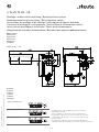
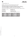
Abmessungen
Dimensions
Dimensions
Dimensioni
Dimensões
Габариты
Ex ZS 73 SR ... -3D
Kontakte
Contacts
Contacts
Contatti
Contatos
Контакты
Ex ZS 73 SR 1Ö/1S-3D
Ex ZS 73 SR 1S/1Ö UE-3D
Ex ZS 73 SR 2Ö-3D
Die dargestellten Schaltsymbole beziehen sich auf den
unbetätigten Zustand.
Contact symbols are shown for the not actuated switch.
Interrupteurs représentés contacts au repos, pas actionnés.
I simboli grafici dei contatti si riferiscono allo stato inattivo
dell’interruttore.
Os símbolos de comutação representam o estado inativo.
Символы контактов показаны для невключенного выключателя.

steute Technologies GmbH & Co. KG
Brückenstraße 91, 32584 Löhne, Germany, www.steute.com
11 / 16
Montage- und Anschlussanleitung / Bandschieflaufschalter
Mounting and wiring instructions / Belt alignment switch
Instructions de montage et de câblage / Interrupteur de déport de bande
Istruzioni di montaggio e collegamento / Interruttore di allineamento nastro
Instruções de montagem e instalação / Chave de desalinhamento
Инструкция по монтажу и подключению / Выключатель перекоса движения ленты
//
Ex ZS 73 SR - 3D
English
Deutsch (Originalbetriebsanleitung)
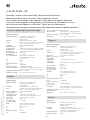
Technische Daten
Angewandte Normen EN 60947-5-1, EN 60947-5-5;
EN 60079-0, EN 60079-31;
EN ISO 13849-1
Gehäuse Aluminium-Druckguss, lackiert
Deckel glasfaserverstärkter, schlagfester Thermo-
plast, selbstverlöschend UL 94-V0
Schutzart IP67; IP65 nach EN 60529
Kontaktmaterial Silber
Schaltelemente 1 Öffner/1 Schließer oder 2 Öffner, Form Zb
Schaltsystem Schleichschaltung, Öffner zwangsöffnend
A
Anschlussart Schraubanschlussklemmen
Leitungseinführung M20 x 1,5
Klemmbereich 6 ... 12 mm
B
10d
(10% Nennlast) Ex ZS 73 SR-3D: 2 Millionen,
Ex ZS 73 SR VD-3D: 200 000
T
M
max. 20 Jahre
U
i
250 V
I
the
6 A
Gebrauchskategorie AC-15
I
e
/U
e
6 A/250 VAC
Kurzschlussschutz 6 A gG/gN-Sicherung
Mechan. Lebensdauer Ex ZS 73 SR-3D: 1 Millionen Schaltspiele,
Ex ZS 73 SR VD-3D: >100 000 Schaltspiele
Umgebungstemperatur -20 °C … +65 °C
Ex-Kennzeichnung
L II 3D Ex tc IIIC T80°C Dc
Technical data
Applied standards EN 60947-5-1, EN 60947-5-5;
EN 60079-0, EN 60079-31;
EN ISO 13849-1
Enclosure aluminium die-cast, enamel finish
Cover fibreglass-reinforced, shockproof thermo-
plastic, self-extinguishing UL 94-V0
Degree of protection IP67; IP65 to EN 60529
Contact material silver
Switching elements 1 NC/1 NO or 2 NC, type Zb
Switching system slow action, positive break NC contacts
A
Connection screw connection terminals
Cable entry M20 x 1.5
Clamping range 6 ... 12 mm
B
10d
(10% nominal
load) Ex ZS 73 SR-3D: 2 millions,
Ex ZS 73 SR VD-3D: 200 000
T
M
max. 20 years
U
i
250 V
I
the
6 A
Utilisation category AC-15
I
e
/U
e
6 A/250 VAC
Short-circuit protection 6 A gG/gN fuse
Mechanical life Ex ZS 73 SR-3D: 1 million operations,
Ex ZS 73 SR VD-3D: >100 000 operations
Ambient temperature -20°C … +65°C
Ex marking
L II 3D Ex tc IIIC T80°C Dc
Français
Données techniques
Normes appliquées EN 60947-5-1, EN 60947-5-5;
EN 60079-0, EN 60079-31;
EN ISO 13849-1
Boîtier fonte d’aluminium, peint
Couvercle thermoplastique renforcé de fibres de verre,
résilient, auto-extinguible UL 94-V0
Etanchéité IP67; IP65 selon EN 60529
Matérie des contacts argent
Eléments de
commutation 1 NF/1 NO ou 2 NF, type Zb
Système de
commutation action dépendante, contact NF à ouverture
positive
A
Raccordement bornes à vis
Entrée de câble M20 x 1,5
Plage de serrage 6 ... 12 mm
B
10d
(10% charge
nominal) Ex ZS 73 SR-3D: 2 millions,
Ex ZS 73 SR VD-3D: 200 000
T
M
max. 20 ans
U
i
250 V
I
the
6 A
Catégorie d’utilisation AC-15
I
e
/U
e
6 A/250 VAC
Protection contre les
courts-circuits fusible 6 A gG/gN
Durée de vie
mécanique Ex ZS 73 SR-3D: 1 million manoeuvres,
Ex ZS 73 SR VD-3D: >100 000 manoeuvres
Température ambiante -20 °C … +65 °C
Protection anti-
déflagrante L II 3D Ex tc IIIC T80°C Dc
Dati tecnici
Norme applicate EN 60947-5-1, EN 60947-5-5;
EN 60079-0, EN 60079-31;
EN ISO 13849-1
Custodia alluminio pressofuso, laccato
Coperchio termoplastica rinforzata con fibre di vetro,
antiurto, autoestinguente UL 94-V0
Grado di protezione IP67; IP65 secondo EN 60529
Materiale contatti argento
Italiano

steute Technologies GmbH & Co. KG
Brückenstraße 91, 32584 Löhne, Germany, www.steute.com
12 / 16
Montage- und Anschlussanleitung / Bandschieflaufschalter
Mounting and wiring instructions / Belt alignment switch
Instructions de montage et de câblage / Interrupteur de déport de bande
Istruzioni di montaggio e collegamento / Interruttore di allineamento nastro
Instruções de montagem e instalação / Chave de desalinhamento
Инструкция по монтажу и подключению / Выключатель перекоса движения ленты
//
Ex ZS 73 SR - 3D
Português
Dados técnicos
Normas aplicáveis EN 60947-5-1, EN 60947-5-5;
EN 60079-0, EN 60079-31;
EN ISO 13849-1
Invólucro alumínio fundido sob pressão, pintado
Tampa termoplástico reforçado com fibras de vidro,
resistente a impacto,
autoextintor UL 94-V0
Grau de proteção IP67; IP65 conforme EN 60529
Contatos prata
Elementos de
comutação 1 NF/1 NA ou 2 NF, tipo Zb
Sistema de comutação ação lenta, contato NF de ruptura forçada
A
Conexão bornes a parafuso
Entrada de cabo M20 x 1,5
Escala de aperto 6 ... 12 mm
B
10d
(10% carga
nominal) Ex ZS 73 SR-3D: 2 milhões,
Ex ZS 73 SR VD-3D: 200 000
T
M
máx. 20 anos
U
i
250 V
I
the
6 A
Categoria de utilização AC-15
I
e
/U
e
6 A/250 VAC
Proteção contra
curto-circuito fusível 6 A gG/gN
Elementi di
commutazione 1 NC/1 NA oppure 2 NC, tipo Zb
Sistema di
commutazione commutazione lenta, contatto NC ad apertura
obbligata
A
Collegamento morsetti a vite
Passacavo M20 x 1,5
Campo di serraggio 6 ... 12 mm
B
10d
(10% carico
nominale) Ex ZS 73 SR-3D: 2 milioni,
Ex ZS 73 SR VD-3D: 200 000
T
M
max. 20 anni
U
i
250 V
I
the
6 A
Categoria d'impiego AC-15
I
e
/U
e
6 A/250 VAC
Protezione da
cortocircuito 6 A gG/gN fusibile
Durata meccanica Ex ZS 73 SR-3D: 1 milione di manovre,
Ex ZS 73 SR VD-3D: >100 000 di manovre
Temperatura
circostante -20 °C … +65 °C
Protezione anti-
deflagrante
L II 3D Ex tc IIIC T80°C Dc
Italiano
Durabilidade mecânica Ex ZS 73 SR-3D: 1 milhões de operações,
Ex ZS 73 SR VD-3D: >100 000 de operações
Temperatura ambiente -20 °C … +65 °C
Classificação Ex
L II 3D Ex tc IIIC T80°C Dc
Русский
Технические данные
Примененные нормы EN 60947-5-1, EN 60947-5-5;
EN 60079-0, EN 60079-31;
EN ISO 13849-1
Корпус алюминиевый сплав, литой под давлением,
лакированый
Kрышка армированный стекловолокном, ударопроч-
ный термопластик, не поддерживающий
горение UL 94-V0
Класс защиты IP67; IP65 по EN 60529
Материал контактов серебро
Коммутирующие
элементы 1 НЗ/1 НР или 2 НЗ, тип Zb
Коммутирующая
система плавное переключение, НЗ с положитель-
ным размыкаемым контактом
A
Вид подключения резьбовые клеммы
Кабельный ввод M20 x 1,5
Диапазон зажима 6 ... 12 мм
B
10d
(10% номиналь-
ной нагрузки) Ex ZS 73 SR-3D: 2 миллиона,
Ex ZS 73 SR VD-3D: 200 000
T
M
мaкc. 20 лeт
U
i
250 V
I
the
6 A
Категории
использования AC-15
I
e
/U
e
6 A/250 VAC
Защита от короткого
замыкания 6 A gG/gN предохранитель
Механ. долговечность Ex ZS 73 SR-3D: 1 миллион циклы
коммутации,
Ex ZS 73 SR VD-3D: >100 000 циклы
коммутации
Температура окру-
жающей среды -20 °C … +65 °C
Взрывная
защищенность
L II 3D Ex tc IIIC T80°C Dc

steute Technologies GmbH & Co. KG
Brückenstraße 91, 32584 Löhne, Germany, www.steute.com
13 / 16
Montage- und Anschlussanleitung / Bandschieflaufschalter
Mounting and wiring instructions / Belt alignment switch
Instructions de montage et de câblage / Interrupteur de déport de bande
Istruzioni di montaggio e collegamento / Interruttore di allineamento nastro
Instruções de montagem e instalação / Chave de desalinhamento
Инструкция по монтажу и подключению / Выключатель перекоса движения ленты
//
Ex ZS 73 SR - 3D
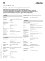
Herstellungsdatum 012220 => Montag KW 22 / 2020
Production date Monday CW 22 / 2020
Date de fabrication lundi semaine 22 / 2020
Data di produzione lunedi settimana 22 / 2020
Data de fabricação segunda semana 22 / 2020
Дата изготовления понедельник календарная неделя 22 / 2020
01 Montag Monday lundi lunedi segunda понедельник
02 Dienstag Tuesday mardi martedì terça вторник
03 Mittwoch Wednesday mercredi mercoledì quarta среда
04 Donnerstag Thursday jeudi giovedì quinta четверг
05 Freitag Friday vendredi venerdì sexta пятница

steute Technologies GmbH & Co. KG
Brückenstraße 91, 32584 Löhne, Germany, www.steute.com
14 / 16
Montage- und Anschlussanleitung / Bandschieflaufschalter
Mounting and wiring instructions / Belt alignment switch
Instructions de montage et de câblage / Interrupteur de déport de bande
Istruzioni di montaggio e collegamento / Interruttore di allineamento nastro
Instruções de montagem e instalação / Chave de desalinhamento
Инструкция по монтажу и подключению / Выключатель перекоса движения ленты
//
Ex ZS 73 SR - 3D
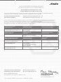
Als Hersteller trägt die Firma steute Technologies die alleinige Verantwortung für die Ausstellung dieser Konformitätserklärung
/
As manufacturer, steute Technologies is solely responsible for issuing this Declaration of Conformity.
Art und Bezeichnung der Betriebsmittel
/
Ex Bandschieflaufschalter, Typen Ex ZS 73 SR ... -3D
Type and name of equipment: Ex belt alignment switch, types Ex ZS 73 SR ... -3D
Hiermit erklären wir, dass die oben aufgeführten elektrischen Betriebsmittel aufgrund der Konzipierung und Bauart den grundlegenden
Sicherheits- und Gesundheitsanforderungen nach Anhang II der Richtlinie 2014/34/EU entsprechen. /
We hereby declare that, due to its design and construction, the above mentioned electrical equipment satisfies the requirements of directive
2014/34/EU in respect to basic safety and health requirements according to Annex II.
Angewandte EU-Richtlinie
/
Applied EU directive
Harmonisierte Normen
/
Harmonised standards
Neueste harmonisierte Normen
/
Latest harmonised standards
2014/34/EU Explosionsschutzrichtlinie
/
2014/34/EU Explosion Protection Directive
EN IEC 60079-0:2018,
EN 60079-31:2014
Weitere angewandte EU-Richtlinien
/
Additionally applied EU directives
Harmonisierte Normen
/
Harmonised standards
Anmerkungen
/
Comments
2014
/
35
/
EU Niederspannungsrichtlinie
/
2014
/
35
/
EU Low Voltage Directive
EN 60947-5-1:2017 -
2014
/
30
/
EU EMV-Richtlinie
/
2014
/
30
/
EU EMC Directive
nicht anwendbar nach EN 60947-1:2007
+A1:2011 +A2:2014
not applicable to EN 60947-1:2007
+A1:2011 +A2:2014
-
2011
/
65
/
EU RoHS-Richtlinie
/
2011
/
65
/
EU RoHS Directive
EN 50581:2012
-
EU-KONFORMITÄTSERKLÄRUNG
EU DECLARATION OF CONFORMITY
gemäß der Explosionsschutz-Richtlinie 2014
/
34
/
EU
according to Explosion Protection Directive 2014
/
34
/
EU
Rechtsverbindliche Unterschrift,
Marc Stanesby (Geschäftsführer)
/
Legally binding signature,
Marc Stanesby (Managing Director)
EG-Baumusterprüfung
/
EU-type examination:
Ex-Kennzeichnung /
Ex marking
Neueste Ex-Kennzeichnung
/
Latest Ex marking
L II 3D Ex tc IIIC T80°C/T95°C Dc
steute Technologies GmbH & Co KG, Brückenstr. 91, 32584 Löhne, Germany
Löhne, 19. Mai 2020 / May 19, 2020
Ort und Datum der Ausstellung
/
Place and date of issue
Verantwortlich technische Dokumentation /
Responsible for technical documentation:
Marc Stanesby (Geschäftsführer)
Marc Stanesby (Managing Director)

steute Technologies GmbH & Co. KG
Brückenstraße 91, 32584 Löhne, Germany, www.steute.com
15 / 16
Montage- und Anschlussanleitung / Bandschieflaufschalter
Mounting and wiring instructions / Belt alignment switch
Instructions de montage et de câblage / Interrupteur de déport de bande
Istruzioni di montaggio e collegamento / Interruttore di allineamento nastro
Instruções de montagem e instalação / Chave de desalinhamento
Инструкция по монтажу и подключению / Выключатель перекоса движения ленты
//
Ex ZS 73 SR - 3D
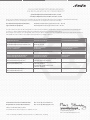
Als Hersteller trägt die Firma steute Technologies die alleinige Verantwortung für die Ausstellung dieser Konformitätserklärung
/
As manufacturer, steute Technologies is solely responsible for issuing this Declaration of Conformity.
Art und Bezeichnung der Betriebsmittel
/
Ex Bandschieflaufschalter, Typen Ex ZS 73 SR … VD -3D
Type and name of equipment: Ex belt alignment switch, types Ex ZS 73 SR … VD -3D
Hiermit erklären wir, dass die oben aufgeführten elektrischen Betriebsmittel aufgrund der Konzipierung und Bauart den grundlegenden
Sicherheits- und Gesundheitsanforderungen nach Anhang II der Richtlinie 2014/34/EU entsprechen. /
We hereby declare that, due to its design and construction, the above mentioned electrical equipment satisfies the requirements of directive
2014/34/EU in respect to basic safety and health requirements according to Annex II.
Angewandte EU-Richtlinie
/
Applied EU directive
Harmonisierte Normen
/
Harmonised standards
Neueste harmonisierte Normen
/
Latest harmonised standards
2014/34/EU Explosionsschutzrichtlinie
/
2014/34/EU Explosion Protection Directive
EN IEC 60079-0:2018,
EN 60079-31:2014
Weitere angewandte EU-Richtlinien
/
Additionally applied EU directives
Harmonisierte Normen
/
Harmonised standards
Anmerkungen
/
Comments
2006
/
42
/
EG Maschinenrichtlinie
/
2006
/
42
/
EC Machinery Directive
EN 60947-5-1:2017; EN 60947-5-5:1997
+A1:2005 +A11:2013 +A2:2017
-
2014
/
30
/
EU EMV-Richtlinie
/
2014
/
30
/
EU EMC Directive
nicht anwendbar nach EN 60947-1:2007
+A1:2011 +A2:2014
not applicable to EN 60947-1:2007
+A1:2011 +A2:2014
-
2011
/
65
/
EU RoHS-Richtlinie
/
2011
/
65
/
EU RoHS Directive
EN 50581:2012
-
EU-KONFORMITÄTSERKLÄRUNG
EU DECLARATION OF CONFORMITY
gemäß der Explosionsschutz-Richtlinie 2014
/
34
/
EU
according to Explosion Protection Directive 2014
/
34
/
EU
Rechtsverbindliche Unterschrift,
Marc Stanesby (Geschäftsführer)
/
Legally binding signature,
Marc Stanesby (Managing Director)
EG-Baumusterprüfung
/
EU-type examination:
Ex-Kennzeichnung /
Ex marking
Neueste Ex-Kennzeichnung
/
Latest Ex marking
L II 3D Ex tc IIIC T80°C/T95°C Dc
steute Technologies GmbH & Co KG, Brückenstr. 91, 32584 Löhne, Germany
Löhne, 19. Mai 2020 / May 19, 2020
Ort und Datum der Ausstellung
/
Place and date of issue
Verantwortlich technische Dokumentation /
Responsible for technical documentation:
Marc Stanesby (Geschäftsführer)
Marc Stanesby (Managing Director)

steute Technologies GmbH & Co. KG
Brückenstraße 91, 32584 Löhne, Germany, www.steute.com
Zusatzinformation zu Montage- und Anschlussanleitungen
Additional information on mounting and wiring instructions
Information complémentaire aux instructions de montage et de câblage
Ulteriori informazioni sulle istruzioni di collegamento e montaggio
Informação adicional para as instruções de montagem
Дополнительная информация по монтажу и инструкциям по подключению
Auf Anfrage erhalten Sie diese Montage- und Anschlussanleitung auch
in Ihrer Landessprache.
This mounting and wiring instruction is also available in your national
language on request.
Ces Instructions de montage et de câblage sont disponibles sur de-
mande, dans votre langue nationale.
Questa istruzione di collegamento e montaggio e'inoltre disponibile
nella vostra lingua su richiesta.
Estas instrucciones de montaje y conexionado se pueden solicitar en
su idioma.
Instruções de ligação e montagem podem ser disponibilizadas em ou-
tros idiomas também - consulte-nos.
Εφόσον το ζητήσετε λαμβάνετε αυτές τις οδηγίες τοποθέτησης και
σύνδεσης και στην γλώσσα της χώρας σας.
Niniejsza instrukcja montażu i podłączenia jest dostępna na życzenie w
języku polskim.
Op aanvraag kunt u deze montage- en installatiehandleiding ook in uw
taal verkrijgen.
Den här monterings- och elinstallationsinstruktionen finns även till-
gänglig på ditt nationella språk efter förfrågan.
På anmodning kan De også rekvirere denne montage- og tilslutnings-
vejledning på Deres eget sprog.
Pyydettäessä asennus- ja kykentäohjeet on saatavana myös sinun
omalla äidinkielellä.
При поискване Вие ще получите тази асамблея, а също и връзката
ръчно майчиния си език.
La cererea Dumneavoastră, vă trimitem instrucţiunile de folosire şi
instrucţiunile de montaj şi în limba romana.
Na požádání obdržíte tento návod na montáž a připojení také v jazyce
vaší země.
Na vyžiadanie obdržíte tento návod na montáž a pripojenie takisto v
jazyku vašej krajiny.
Egyeztetés után, kérésére, ezt a szerelési- és csatlakoztatási leírást,
biztosítjuk az Ön anyanyelvén is.
Na zahtevo boste dobili ta navodila za montažo in priklop tudi v vašem
domačem jeziku.
Na zahtjev ćete dobiti ova uputstva za montažu i priključenje i na svom
jeziku.
Dan il-manwal dwar il-muntaġġ u konnessjonijiet huwa disponibbli
wkoll fil-lingwa tiegħek.
Soovi korral on see installimis- ja ühendusjuhend saadaval ka teie
riigikeeles.
Jei jums reikėtų šios įdiegimo ir pajungimo instrukcijos valstybine
kalba, teiraukitės pardavėjo.
Šo montāžas un pieslēgšanas instrukciju pēc pieprasījuma varat
saņemt arī savas valsts valodā.
Arna iarraidh sin gheobhaidh tú na treoracha tionóil agus na treorach
seo i do theanga féin.
16 / 16
01.26.0353 / 117 35 63 / 05.2020 / 138857.Index a
-
 1
1
-
 2
2
-
 3
3
-
 4
4
-
 5
5
-
 6
6
-
 7
7
-
 8
8
-
 9
9
-
 10
10
-
 11
11
-
 12
12
-
 13
13
-
 14
14
-
 15
15
-
 16
16


steute EX ZS 73 SR 1S/1Ö UE-3D Mounting And Wiring Instructions
- Tipo
- Mounting And Wiring Instructions
- Questo manuale è adatto anche per
in altre lingue
- English: steute EX ZS 73 SR 1S/1Ö UE-3D
- français: steute EX ZS 73 SR 1S/1Ö UE-3D
- Deutsch: steute EX ZS 73 SR 1S/1Ö UE-3D
- русский: steute EX ZS 73 SR 1S/1Ö UE-3D
- português: steute EX ZS 73 SR 1S/1Ö UE-3D
Documenti correlati
Altri documenti
-
schmersal EX-RDRZ45RT Istruzioni per l'uso
-
Videotec EXHC000G Manuale utente
-
ABB ATEX Istruzioni per l'uso
-
Kollmorgen SERVOSTAR 500 Safety Manual
-
SICK T4000 Direct Unicode Safety Switch Istruzioni per l'uso
-
-
-
-