Eaton E5524E0402 Operating Instructions Manual
- Tipo
- Operating Instructions Manual

MN05401010E 1
español
englishfrançais
deutsch
italiano
Operating Instructions
Electronic Display Counter
E5524E0402
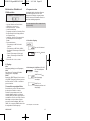
1.1 Safety instructions and warnings
Only use this display
– according to its intended purpose
– if its technical condition is perfect
– adhering to the operating
instructions and the general
safety instructions.
1.2 General safety instructions
1. Before carrying out any installation or mainte-
nance work, make sure that the power supply
of the digital display is switched off.
2. Only use this digital display according to its
intended purpose:
If its technical condition is perfect.
Adhering to the operating instructions and the
general safety instructions.
3. Adhere to country or user specific regulations.
4. The digital display is not intended for use in
areas with risks of explosion and in the
branches excluded by the standard EN 61010
Part 1.
5. The digital display shall only operated if it has
been correctly mounted in a panel, in accor-
dance with the chapter “Main technical fea-
tures”.
1.3 Use according to the intended
purpose
The digital display may only be used as a panel-
mounted device. Applications of this product may
be found in industrial processes and controls, in
manufacturing lines for the metal, wood, plastics,
paper, glass, textile and other processing
industries.
Over-voltages at the terminals of the digital dis-
play must be kept within the limits in Category II.
If the digital display is used to monitor machines
or processes in which, in case of a failure of the
device or an error made by the operator, there
might be risks of damaging the machine or caus-
ing accidents to the operators, it is your respon-
sibility to take appropriate safety measures.
1.4 Description
E5524E0402 is a multipurpose device.
Depending on the programmed basic function,
the device operates like
• an electronic totalizer and frequency meter
(see page 2)
• an electronic display counter with
2 totalizing ranges (see page 4)
• an electronic totalizer and time meter
(see page 6)
• an electronic time meter with 2 time ranges
(see page 9)
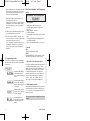
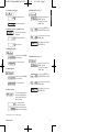
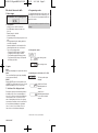
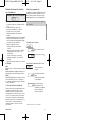
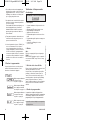
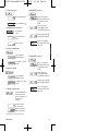
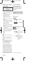
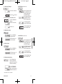
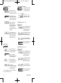
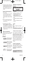
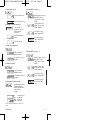
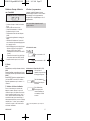
2. Setting of the operating pa ra me ters
a. Press both front side keys and switch on the
supply voltage or, if the supply voltage is
already on, press both keys simultaneously
for 5 s.
b. The display shows
c. After releasing the keys, the display shows
c1.Hold the left key pressed and press the right
key to exit the programming operation.
c2.Press the right key to switch to
.
d. Hold the left key pressed and press the right
key to switch to the first parameter.
!
MN05401010E.qxd:MN05401010E 7/31/12 9:10 AM Page 1

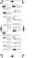
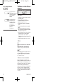
e. After releasing the keys, the display alternates
between the menu title and the current menu
item setting. After pressing any key, only the
menu item setting is displayed.
f. Pressing the right key will switch the menu
item setting to the next value.
If figures are to be input (e.g. when setting the
scaling factor), select first the decade using
the left key, and then set the value using the
right key.
g. Hold the left key pressed and press the right
key to switch to the next menu item.
h. The last menu title “EndPro” allows the user,
when selecting “Yes”, to exit the programming
menu and to store the new values.
If “no” is selected, the programming routine is
repeated, the latest values set remaining
active. They can now be checked again or
modified.
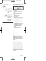
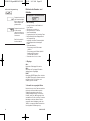
3. Programming routine
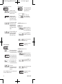
The first menu item is the selection of the basic
operating mode, which determines the functions
of the device.
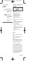
Electronic totalizer and frequency
meter
1. Description
•
6-digit totalizer
and frequency meter
• Red LED display, character height 8 mm
[0.31 in.]
• Display range 0 – 999 999
• Lead zero blanking
• Programming via two setting keys on the front
side
• During programming, the display guides the
user with text prompts
• Value conversion and display in 1/s or 1/min
2. Inputs
INP A
Dynamic count/frequency input.
RESET
Dynamic RESET input. Linked in parallel to the
red RESET key. Resets the counter to zero.
3. Selection of the displayed value
Pressing the right key allows switching between
the totalizer display and the frequency meter
display. Press the key briefly to display the cur-
rent function (“total” or “tacho”) for 2 seconds.
If, during this period of time, the right key is
pressed a second time, the device switches to
the next function and displays a confirmation
(“total” or “tacho”) for 2 seconds. Then, the
value of the selected function is displayed.
4. Programming routine
The programmable parameters of the device are
described below, in the order in which they can
be set. The device is fully programmed after one
pass of the routine.
The first values stated correspond to the factory
settings.
2 MN05401010E
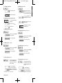
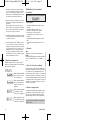
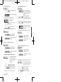
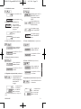
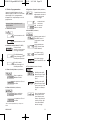
Operating mode adding
counter and frequency
meter,
continued in point 4
below
Operating mode display
counter with 2 totalizing
ranges,
continued in point
4
on page 4
Operating mode totalizer
and time meter,
continued
in point 4
on page 7
Operating mode time
meter with 2 time ranges,
continued in point 4
on
page 9
- Subject to change without prior notice -
E5524E0402: basic operating mode
MN05401010E.qxd:MN05401010E 7/31/12 9:10 AM Page 2

MN05401010E 3
english
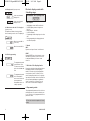
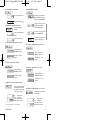
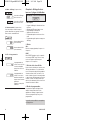
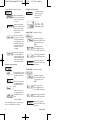
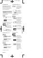
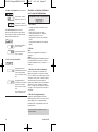
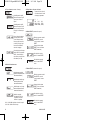
4.1 Polarity of the inputs
npn: sinking sensor
pnp: sourcing sensor
4.2 Switching on the 30 Hz filter (INP A)
It can be set from 00.0001
up to 99.9999.
“0” is not accepted!
4.3 Multiplying factor (totalizer)
It can be set from 00.0001
up to 99.9999.
“0” is not accepted!
4.4 Dividing factor ( totalizer)
The decimal point defines
the way of displaying the
count values. It does not
affect counting.
0 no decimal place
0.0 one decimal place
0.00 two decimal places
0.000
three decimal places
4.5 Decimal point (totalizer)
4.6 RESET mode (totalizer)
manual reset via the red
RESET key and electrical
reset via the RESET input
no reset (red RESET key
and RESET input locked)
only electrical reset via the
RESET input
only manual reset via the
red RESET key
4.7 Multiplying factor (frequency meter)
It can be set from 00.0001
up to 99.9999.
“0” is not accepted!
It can be set from 00.0001
up to 99.9999.
“0” is not accepted!
4.8 Dividing factor (frequency meter)
The decimal point defines
the resolution in the select-
ed measuring range 1/min
or 1/sec
0 no decimal place
0.0 one decimal place
0.00 two decimal places
0.000
three decimal places
4.9 Decimal point (frequency meter)
The filter provides input
damping*
30 Hz filter off (f
max
)
30 Hz filter on
* where bounce occurs, e.g. with contacts
MN05401010E.qxd:MN05401010E 7/31/12 9:10 AM Page 3

4 MN05401010E
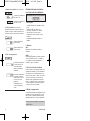
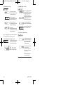
4.12 End of programming
The programming routine
is repeated once more.
The values set until now
can be checked and mod-
ified.
The programming routine
will be exited and all
values set will be stored
as new parameters.
Afterwards the device is
ready for operation.
4.10 Display mode (frequency meter)
Value conversion and
display in 1/s
Value conversion and
display in 1/min
4.11 Max. time to wait until “0” is displayed
(frequency meter)
This parameter indicates, how long it takes,
when measuring is active, until “0” is displayed.
Max. time to wait 00.1 s
(min. value)
Max. time to wait 99.9 s
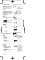
Electronic display counter with
2 totalizing ranges
1. Description
• 6-digit display counter with Reset function
• Red LED display, character height 8 mm
[0.31 in.]
• Display range 0 – 999 999
• Lead zero blanking
• Programming via two setting keys on the front
side
• During programming, the display guides the
user with text prompts
2. Inputs
INP A
Dynamic count input Counter 1 and Counter 2.
RESET
Dynamic RESET input. Linked in parallel to the
red RESET key. Sets the counter to zero. Can
be adjusted individually for Counter 1 and
Counter 2.
3. Selection of the displayed value
Pressing the right key allows switching between
the display of totalizer 1 and the display of
totalizer 2. Press the key briefly to display the
current function (“total1” or “total2”) for 2 sec-
onds. If, during this period of time, the right key
is pressed a second time, the device switches to
the next function and displays a confirmation
(“total1” or “total2”) for 2 seconds. Then, the
value of the selected function is displayed.
4. Programming routine
The programmable parameters of the device are
described below, in the order in which they can
be set. The device is fully programmed after one
pass of the routine.
The first values stated correspond to the factory
settings.
E5524E0402: basic operating mode
MN05401010E.qxd:MN05401010E 7/31/12 9:10 AM Page 4

MN05401010E 5
english
4.1 Polarity of the inputs
npn: sinking sensor
pnp: sourcing sensor
4.2 Switching on the 30 Hz filter (INP A)
30 Hz filter off (f
max
)
30 Hz filter on
It can be set from 00.0001
up to 99.9999.
“0” is not accepted!
4.3 Multiplying factor
It can be set from 00.0001
up to 99.9999.
“0” is not accepted!
4.4 Dividing factor
The decimal point defines
the way of displaying the
count values. It does not
affect counting.
0 no decimal place
0.0 one decimal place
0.00 two decimal places
0.000
three decimal places
4.5 Decimal point
4.6 RESET mode (totalizer 1)
manual reset via the red
RESET key and
electrical reset via the
RESET input
no reset (red RESET key
and RESET input locked)
only electrical reset via the
RESET input
only manual reset via the
red RESET key
4.7 RESET mode (totalizer 2)
manual reset via the red
RESET key and
electrical reset via the
RESET input
no reset (red RESET key
and RESET input locked)
only electrical reset via the
RESET input
only manual reset via the
red RESET key
* where bounce occurs, e.g. with contacts
The filter provides input
damping*
MN05401010E.qxd:MN05401010E 7/31/12 9:10 AM Page 5

6 MN05401010E
4.8 End of programming
The programming routine
is repeated once more.
The values set until now
can be checked and
modified.
The programming routine
will be exited and all
values set will be stored
as new parameters.
Afterwards the device is
ready for operation.
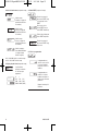
Electronic totalizer and time meter
1. Description
• 6 digit totalizer and time meter with Reset
function
• Red LED display, character height 8 mm
[0.31 in.]
• Display range 0 – 999 999
• Lead zero blanking
• Programming via two setting keys on the front
side
• During programming, the display guides the
user with text prompts
• Operation indicator: the decimal point of the
lowest digit blinks while the count is active.
• Time meter operating modes:
– Counting while INP B is inactive “GAtE.Lo”
– Counting while INP B is active “GAtE.hi”
– Count Start/Stop with INP B edge B
“Inb.Inb”
• Counting ranges: h; min; s; h.min.s
2. Inputs
INP A
Dynamic count input for the totalizer.
INP B
Start-/Stop or gate input for time meter
(independent of the input mode)
RESET
Dynamic RESET input. Linked in parallel to the
red RESET key. Sets the counter to zero. Can
be adjusted individually for the totalizer and the
time meter.
3. Selection of the displayed value
Pressing the right key allows switching between
the totalizer display and the time meter display.
Press the key briefly to display the current func-
tion (“total” or “time”) for 2 seconds. If, during this
period of time, the right key is pressed a second
time, the device switches to the next function
and displays a confirmation (“total” or “time”) for
2 seconds. Then, the value of the selected func-
tion is displayed.
E5524E0402: basic operating mode
MN05401010E.qxd:MN05401010E 7/31/12 9:10 AM Page 6

MN05401010E 7
english
4. Programming routine
The programmable parameters of the device are
described below, in the order in which they can
be set. The device is fully programmed after one
pass of the routine.
The first values stated correspond to the factory
settings.
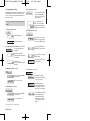
4.1 Polarity of the inputs
npn: sinking sensor
pnp: sourcing sensor
4.2 Switching on the 30 Hz filter (INP A, INP B)
30 Hz filter off (f
max)
Count and start/stop inputs
not damped
30 Hz filter on
Count and start/stop inputs
damped
It can be set from 00.0001
up to 99.9999.
“0” is not accepted!
4.3 Multiplying factor (totalizer)
It can be set from 00.0001
up to 99.9999.
“0” is not accepted!
4.4 Dividing factor (totalizer)
The decimal point defines
the way of displaying the
count values. It does not
affect counting.
0 no decimal place
0.0 one decimal place
0.00 two decimal places
0.000
three decimal places
4.5 Decimal point (totalizer)
4.6 RESET mode (totalizer)
manual reset via the red
RESET key and electrical
reset via the RESET input
no reset (red RESET key
and RESET input locked)
only electrical reset via the
RESET input
only manual reset via the
red RESET key
Start/Stop via Inp B.
Timing while Inp B (Gate)
not active or open
Start/Stop via Inp B.
Timing while Inp B (Gate)
active (High level with
pnp; Low level with npn)
Time
Start/Stop via
INP B
(LOW-HIGH edge with
pnp; HIGH-LOW edge
with npn). Every active
edge changes the timer
status.
4.7 Input mode (time meter)
* where bounce occurs, e.g. with contacts
The filter provides input
damping*
MN05401010E.qxd:MN05401010E 7/31/12 9:10 AM Page 7

8 MN05401010E
Time unit: seconds (reso-
lution depending on posi-
tion of the decimal point*)
Time unit: minutes (reso-
lution depending on posi-
tion of the decimal point*)
Time unit: hours (resolu-
tion depending on posi-
tion of the decimal point*)
Time units:
Hours:Minutes:Seconds
(decimal point setting is
ignored)
4.8 Operating mode (time meter)
*0, 0.1, 0.01, 0.001 means: time measurement in
0, 0.1, 0.01, 0.001 time units
4.9 Decimal point (time meter)
The decimal point defines
the resolution of the pro -
gram med time unit.
0 1
0.0 1/10 (0.1)
0.00 1/100 (0.01)
0.000 1/1000 (0.001)
4.11 End of programming
The programming routine
is repeated once more.
The values set until now
can be checked and
modified.
The programming routine
will be exited and all
values set will be stored
as new parameters.
Afterwards the device is
ready for operation.
4.10 RESET mode (time meter)
manual reset via the red
RESET key and electrical
reset via the RESET input
no reset (red RESET key
and RESET input locked)
only electrical reset via the
RESET input
only manual reset via the
red RESET key
MN05401010E.qxd:MN05401010E 7/31/12 9:10 AM Page 8

MN05401010E 9
english
Electronic time meter with
2 time ranges
1. Description
• 6 digit time meter with Reset function
• Red LED display, character height 8 mm
[0.31 in.]
• Display range 0 – 999 999
• Lead zero blanking
• Programming via two setting keys on the front
side
• During programming, the display guides the
user with text prompts
• Operation indicator: the decimal point of the
lowest digit blinks while the count is active
• Time meter operating modes:
– Timing while INP B is inactive “GAtE.Lo”
– Timing while INP B is active “GAtE.hi”
– Time Start/Stop with INP B edge (Inb.Inb)
– Time Start with INP A edge, time Stop with
INP B edge (InA.InB)
2. Inputs
INP A
Start input (depending on the input mode chosen)
INP B
Time meter Start/Stop or gate input (depending
on the input mode chosen)
RESET
Dynamic RESET input. Linked in parallel to the
red RESET key. Resets the timer to zero. Can be
adjusted individually for Timer 1 and Timer 2.
3. Selection of the displayed value
Pressing the right key allows switching between
the display of time meter 1 and the display of
time meter 2. Press the key briefly to display the
current function (“time1” or “time2”) for 2 sec-
onds. If, during this period of time, the right key
is pressed a second time, the device switches to
the next function and displays a confirmation
(“time1” or “time2”) for 2 seconds. Then, the
value of the selected function is displayed.
4. Programming routine
The programmable parameters of the device are
described below, in the order in which they can
be set. The device is fully programmed after one
pass of the routine.
The first values stated correspond to the factory
settings.
4.1 Polarity of the inputs
npn: sinking sensor
pnp: sourcing sensor
4.2 Switching on the 30 Hz filter (INP A, INP B)
30 Hz filter off (f
max)
Start/Stop inputs not
damped
30 Hz filter on
Start/Stop inputs damped
for use with me cha nical
switches
* where bounce occurs, e.g. with contacts
The filter provides input
damping*
E5524E0402: basic operating mode
MN05401010E.qxd:MN05401010E 7/31/12 9:10 AM Page 9

10 MN05401010E
4.4 Operating mode
*0, 0.1, 0.01, 0.001 means: time measurement in
0, 0.1, 0.01, 0.001 time units
4.5 Decimal point
The decimal point defines
the resolution of the pro -
gram med time unit.
0 1
0.0 1/10 (0.1)
0.00 1/100 (0.01)
0.000 1/1000 (0.001)
4.7 RESET mode (time meter 2)
manual reset via the red
RESET key and electrical
reset via the RESET input
no reset (red RESET key
and RESET input locked)
only electrical reset via the
RESET input
only manual reset via the
red RESET key
only electrical reset via the
RESET input
only manual reset via the
red RESET key
4.6 RESET mode (time meter 1)
manual reset via the red
RESET key and electrical
reset via the RESET input
no reset (red RESET key
and RESET input locked)
Start/Stop via Inp B.
Timing while Inp B (Gate)
not active or open
Start/Stop via Inp B.
Timing while Inp B (Gate)
active (High level with
pnp; Low level with npn)
Time
Start/Stop via
INP B
(LOW-HIGH edge with
pnp; HIGH-LOW edge
with npn). Every active
edge changes the timer
status.
Time start via INP A, stop
via INP B. (LOW-HIGH
edge with pnp; HIGH-
LOW edge with npn)
4.3 Input mode (time meter)
Time unit: seconds (reso-
lution depending on posi-
tion of the decimal point*)
Time unit: minutes (reso-
lution depending on posi-
tion of the decimal point*)
Time unit: hours (resolu-
tion depending on posi-
tion of the decimal point*)
Time units:
Hours:Minutes:Seconds
(decimal point setting is
ignored)
MN05401010E.qxd:MN05401010E 7/31/12 9:10 AM Page 10

MN05401010E 11
english
4.8 End of programming
The programming routine
is repeated once more.
The values set until now
can be checked and
modified.
The programming routine
wil be exited and all
values set will be stored
as new parameters.
Afterwards the device is
ready for operation.
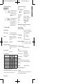
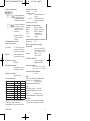
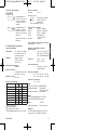
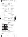
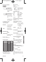
5. Technical data
Supply voltage
Power supply: 10 – 30V DC/max. 40 mA
with inverse-polarity protection
Display: 6 digits, red 7 segment
LED display, height 8 mm
[0.31 in.]
Data retention: EEPROM
Polarity of the inputs:
Programmable, npn or pnp
(sinking or sourcing) for all
inputs
Input resistance:
appr. 5 kΩ
Count frequency:
1)
Start Gate.Lo Inp B not active
2)
Start InpB.InpB and Inp B connected with Inp A
* at maximum frequency square wave pulses 1:1
Frequency measurement:
Error: < 0.1 %
Measuring principle:
<
38 Hz: period measurement
> 38 Hz: gating time measurement
gating time = 26.3 ms
Time ranges:
Seconds 0.001 s – 999 999 s
Minutes 0.001min – 999 999 min
Hours 0.001 h – 999 999 h
h.min.s 00 h 00 min 01 s
– 99 h 59 min 59 s
Error <50 ppm
Minimum pulse length for the Reset input:
5 ms
Input sensitivity:
Standard sensitivity:
Low: 0 – 0.2 x U
B
[V DC]
High: 0.6 x U
B
– 30 [V DC]
U
B
= Supply Voltage
5V sensitivity: Low: 0 – 2V DC
High: 4 – 30V DC
Pulse shape: any,
Schmitt-Trigger inputs
Ambient temperature:
–20 ... +65°C at 10 ... 26 V DC
–20 ... +55°C at >26 ... 30 V DC
Storage temperature:
–25 to +70°C [-9 to 158°F]
EMC:
In compliance with the EC Directive
2004/108/EEC
Noise emission EN 61 000-6-3/
EN 55 011 Class B
Noise immunity EN 61 000-6-2
Housing:
For front panel mounting: 48 x 24 mm
[3.78 x 1.89 in.] acc. to DIN 43700, RAL7021,
dark grey
Weight: appr. 50 g [5.29 oz.]
Front panel rating: IP 65
Cleaning:
The front of the unit is to be cleaned only with a
soft cloth moistened with water.
DC power supply: 24V 12V 10 – 30V
Input level: Standard 5V
typ. low level: 2.5V 2.0V 1.0V
typ. high level: 22.0V 10V 4.0V
Fmax: kHz kHz kHz
tot.tac 35 20 8
tot.tot 60 20 8
tot.ti
1)
40 20 8
tot.ti
2)
15 10 8
MN05401010E.qxd:MN05401010E 7/31/12 9:10 AM Page 11

12 MN05401010E
7. Contents:
1 Digital display
1 Panel mounting clip
1 Bezel for screw mounting, panel cut out
50 x 25 mm [1.97 x 0.98 in.]
1 Bezel for clip mounting, panel cut out
50 x 25 mm [1.97 x 0.98 in.]
1 Seal
1 Multilingual operating instructions
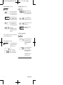
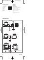
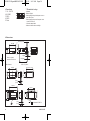
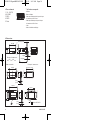
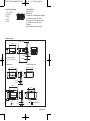
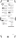
6. Terminal assignment
8. Dimensions in mm [in.]:
1 10 – 30V DC
2 0 V GND
3 INP A
4 INP B
5 Reset
48 [1.89]
max. 19.3 [0.76]
22 x 5 [0.87 x 1.77]
24 [0.94]
59 [2.32]
4 [0.16]
6.5 [0.26]
Panel cut out:
22.2+0.3 x 45+0.6
[0.87+0.01 x 1.77+0.02]
53 [2.09]
50 + 0.6 [1.97 + 0.02]
1 [0.04]
4 [0.16]
25 x 50
[0.98 x 1.97]
26 [1.10]
25 + 0.5
[0.98 + 0.02]
Front bezel Panel cut out:
40 [1.57]
56 [2.20]
25 [0.98]
25 x 50
[0.98 x 1.97]
50 [1.97]
M3
1 [0.04]
4 [0.16]
32 [ 1.26]
1
32 ± 0.01
[1.26 ± 0.004]
Counter sinking
Af3, DIN 74
1
MN05401010E.qxd:MN05401010E 7/31/12 9:10 AM Page 12

MN05401010E 13
español
Instrucciones de puesta en servicio
Contador indicador electrónico
E5524E0402
1.1 Instrucciones de seguridad y
advertencias
Utilizar este visualizador únicamente
– de acuerdo con su función
material
– si se encuentra en perfecto
estado técnico
– respetando las instrucciones
deutilización y las instrucciones
generales de seguridad.
1.2 Instrucciones generales de
seguridad
1. Antes de todo trabajo de instalación o
mantenimiento, asegúrese de que la
alimentación del visualizador digital está
cortada.
2. Utilizar este visualizador únicamente de
acuerdo con su función material:
Si se encuentra en perfecto estado técnico.
Respetando las instrucciones de utilización y
las instrucciones generales de seguridad.
3. Cumplir las normativas correspondientes al
país y al usuario.
4. Este visualizador digital no debe utilizarse en
zonas que presenten riesgo de explosión y en
entornos de uso excluidos de la norma
EN 61 010 Parte 1.
5. Este aparato sólo debe funcionar encajado,
según la normativa profesiona, conforme a lo
indicado en el capítulo “Características
técnicas generales”.
1.3 Utilización correcta
Este visualizador digital sólo puede utilizarse
encajado. La aplicación de este producto
respecta a procesos industriales y de control, en
cadenas de fabricación de industrias del metal,
madera, materias plásticas, papel, vidrio,
textiles, etc. Las sobretensiones en los bornes
del aparato deben limitarse a los valores de la
categoría de sobretensión II.
Si se implanta el visualizador digital para la
vigilancia de máquinas o procesos en los que
puede aparecer un riesgo de daños a la
máquina o accidentes para los operarios en
caso de avería o de un error de manipulación
del aparato, usted tiene la obligación de adoptar
medidas de seguridad apropiadas.
1.4 Descripción
Las prestaciones del E5524E0402 hacen de él
un aparato universal. En función del modo de
funcionamiento seleccionado, se comporta como
• un totalizador y frecuencímetro electrónico
(véase página 14)
•
un contador indicador electrónico con
2 intervalos de totalización (véase página 16)
• un totalizador y contador de tiempo
electrónico (véase página 18)
• un contador de tiempo electrónico con 2
contadores de tiempo (véase página 21)
2. Ajuste de los parámetros de
funcionamiento
a. Pulsar las dos teclas de la cara delantera y
encender el aparato, o, con el aparato encen-
dido, pulsar las dos teclas durante 5 s.
b. En la pantalla aparece el mensaje
c. Cuando se dejan de pulsar las teclas, la pan-
talla indica .
c1. Mantener pulsada la tecla de la izquierda,
luego pulsar la tecla de la derecha para inter-
rumpir la operación de programación.
c2. Pulsar la tecla de la derecha para que la
pantalla indique .
d. Mantener pulsada la teclada de la izquierda,
luego pulsar la tecla de la derecha, para invo-
car el primer parámetro
!
MN05401010E.qxd:MN05401010E 7/31/12 9:10 AM Page 13

e. Cuando se dejan de pulsar las teclas apare-
cen, en intervalos de un segundo, el título del
menú y el ajuste actual del punto del menú.
Pulsar una tecla: la pantalla deja de alternar y
sólo indica el ajuste del punto del menú.
f. Durante el ajuste, si se pulsa una vez la tecla
de la derecha se pasa al valor siguiente del
parámetro.
Para introducir valores numéricos (p. ej., al
ajustar el factor), seleccionar primero la déca-
da con la tecla de la izquierda, luego ajustar
su valor con la tecla de la derecha.
g. Para pasar al siguiente punto del menú, man-
tener pulsada la tecla de la izquierda y pulsar
la tecla de la derecha.
h. El último punto del menú, “EndPro”, permite,
si se selecciona “Yes”, salir del menú de pro-
gramación y asumir (almacenar en memoria)
los nuevos valores. Si se selecciona “no”, la
programación vuelve a comenzar después
del inicio, conservando los últimos valores
introducidos. En ese caso es posible compro-
barlos o modificarlos de nuevo.
3. Rutina de programación
El primer punto del menú es la selección del
modo de funcionamiento básico. Éste determina
las funciones del aparato.
Totalizador y frecuencímetro
electrónico
1. Descripción
• Contador totalizador y frecuencímetro con 6
décadas
• Pantalla de LED rojos, altura 8 mm
• Intervalo de visualización 0 ... 999 999
• Supresión de los ceros en cabeza
• Programación con dos teclas de la cara
delantera
•
Programación guiada por mensajes en la pan-
talla
• Conversión y visualización del valor en 1/s o
1/min
2. Entradas
INP A
Entrada de conteo/de frecuencia dinámica.
RESET
Entrada RESET dinámica conectada en paralelo
con la tecla RESET roja. Pone el contador a
cero.
3. Selección del valor visualizado
Pulsar la tecla de la derecha para cambiar entre
la pantalla del totalizador y la del frecuencímetro.
Si se pulsa una vez se visualiza durante 2 s la
función corriente (“total” o “tacho”). Si se pulsa la
tecla de la derecha de nuevo durante ese lapso
de tiempo, la pantalla pasa a la función actual, y
se visualiza (“total” o “tacho”) durante 2 s. para
confirmación. A continuación aparece el valor de
la función seleccionada.
4. Rutina de programación
Los parámetros ajustables del dispositivo se indi-
can abajo por su orden de aparición en la pan-
talla. Por tanto, el aparato está totalmente pro-
gramado después de un ciclo de programación.
Los primeros valores indicados corresponden al
ajuste de fábrica.
14 MN05401010E
Modo contador totalizador
y frecuencímetro, véase
pár. 4 en página 14
Modo contador indicador
con 2 intervalos de total-
ización, véase pár. 4 en
página 16
Modo contador totalizador
y contador de tiempo,
véase pár. 4 en página 19
Modo contador de tiempo
con 2 intervalos de tiempo,
véase pár. 4 en página 21
- Sin perjuicio de modificaciones técnicas -
E5524E0402: Modo de funcionamiento
MN05401010E.qxd:MN05401010E 7/31/12 9:10 AM Page 14

MN05401010E 15
español
4.1 Polaridad de las entradas
npn: conmutación a 0 V
pnp: conmutación a +U
B
4.2 Activación del filtro 30 Hz (INP A)
Filtro 30 Hz desactivado
(f
max
)
Filtro 30 Hz activado
Factor ajustable de
00.0001 a 99.9999.
El ajuste a “0” no se
acepta.
4.3 Factor de multiplicación (totalizador)
Factor ajustable de
00.0001 a 99.9999.
El ajuste a “0” no se
acepta.
4.4 Factor de división (totalizador)
El punto decimal determina
la representación del valor
de conteo. No tiene ningún
efecto sobre el conteo.
0 sin decimales
0.0 un decimal
0.00 dos decimales
0.000 tres decimales
4.5 Ajuste del punto decimal (totalizador)
4.6 Modo RESET (totalizador)
Puesta a cero manual con
la tecla RESET roja y eléc-
trica por la entrada RESET
No hay puesta a cero (tecla
RESET roja y entrada
RESET desactivadas)
Puesta a cero eléctrica sólo
por la entrada RESET
Puesta a cero manual sólo
por la tecla RESET roja
4.7 Factor de multiplicación (frecuencímetro)
Factor ajustable de
00.0001 a 99.9999.
El ajuste a “0” no se
acepta.
Factor ajustable de
00.0001 a 99.9999.
El ajuste a “0” no se
acepta.
4.8 Factor de división (frecuencímetro)
El punto decimal determina
la resolución.
0 sin decimales
0.0 un decimal
0.00 dos decimales
0.000 tres decimales
4.9 Ajuste del punto decimal (frecuencímetro)
El filtro amortigua la
entrada*
* en caso de rebotes; p. Ej. , con contactos
MN05401010E.qxd:MN05401010E 7/31/12 9:10 AM Page 15

16 MN05401010E
4.12 Fin de la programación
La rutina de programación
se realiza otra vez. Los
valores introducidos
pueden comprobarse y
modificarse.
La rutina de programación
se termina y los valores
introducidos se tienen en
cuenta como nuevos
parámetros.
El dispositivo queda
entonces listo para fun-
cionar.
4.10 Modo de visualización (frecuencímetro)
Conversión y visualización
del valor en 1/s
Conversión y visualización
del valor en 1/min
4.11 Espera máxima (frecuencímetro)
Este valor indica cuánto tiempo debe esperar el
sistema a un impulso, cuando la medición está
en marcha, antes de representar 0 en pantalla.
Espera máxima 00.1 s
(valor mínimo)
Espera máxima 99,9 s
(valor máximo)
Contador indicador electrónico
con 2 intervalos de totalización
1. Descripción
• Contador indicador con 6 décadas y función
Reset
• Pantalla de LED rojos, altura 8 mm
• Intervalo de visualización 0 ... 999 999
• Supresión de los ceros en cabeza
• Programación con dos teclas de la cara
delantera
•
Programación guiada por mensajes en la
pantalla
2. Entradas
INP A
Entrada de conteo dinámica Contador 1 y
Contador 2.
RESET
Entrada RESET dinámica conectada en paralelo
con la tecla RESET roja. Pone el contador a
cero. Ajustable de forma separada para el
Contador 1 y para el Contador 2.
3. Selección del valor visualizado
Pulsar la tecla de la derecha para cambiar entre
la pantalla del totalizador 1 y la del totalizador 2.
Si se pulsa una vez se visualiza durante 2 s la
función corriente (“total1” o “total2”). Si se pulsa
la tecla de la derecha de nuevo durante ese
lapso de tiempo, la pantalla pasa a la función
actual, y se visualiza (“total1” o “total2”) durante
2 s. para confirmación. A continuación aparece
el valor de la función seleccionada.
4. Rutina de programación
Los parámetros ajustables del dispositivo se indi-
can abajo por su orden de aparición en la pan-
talla. Por tanto, el aparato está totalmente pro-
gramado después de un ciclo de programación.
Los primeros valores indicados corresponden al
ajuste de fábrica.
E5524E0402: Modo de funcionamiento
MN05401010E.qxd:MN05401010E 7/31/12 9:10 AM Page 16

MN05401010E 17
español
4.1 Polaridad de las entradas
npn: conmutación a 0 V
pnp: conmutación a +U
B
4.2 Activación del filtro 30 Hz (INP A)
Filtro 30 Hz desactivado
(f
max
)
Filtro 30 Hz activado
Factor ajustable de
00.0001 a 99.9999.
El ajuste a “0” no se
acepta.
4.3 Factor de multiplicación
Factor ajustable de
00.0001 a 99.9999.
El ajuste a “0” no se
acepta.
4.4 Factor de división
El punto decimal determina
la representación del valor
de conteo. No tiene ningún
efecto sobre el conteo.
0 sin decimales
0.0 un decimal
0.00 dos decimales
0.000 tres decimales
4.5 Ajuste del punto decimal
4.6 Modo RESET (totalizador 1)
Puesta a cero manual con
la tecla RESET roja y eléc-
trica por la entrada RESET
No hay puesta a cero (tecla
RESET roja y entrada
RESET desactivadas)
Puesta a cero eléctrica
sólo por la entrada RESET
Puesta a cero manual sólo
por la tecla RESET roja
4.7 Modo RESET (totalizador 2)
Puesta a cero manual con
la tecla RESET roja y eléc-
trica por la entrada RESET
No hay puesta a cero (tecla
RESET roja y entrada
RESET desactivadas)
Puesta a cero eléctrica
sólo por la entrada RESET
Puesta a cero manual sólo
por la tecla RESET roja
El filtro amortigua la
entrada*
* en caso de rebotes; p. Ej. , con contactos
MN05401010E.qxd:MN05401010E 7/31/12 9:10 AM Page 17

18 MN05401010E
4.8 Fin de la programación
La rutina de programación
se realiza otra vez. Los
valores introducidos
pueden comprobarse y
modificarse.
La rutina de programación
se termina y los valores
introducidos se tienen en
cuenta como nuevos
parámetros.
El dispositivo queda
entonces listo para
funcionar.
Totalizador y contador de tiempo
electrónico
1. Descripción
• Totalizador y contador de tiempo
con 6 décadas y función Reset
• Pantalla de LED rojos, altura 8 mm
• Intervalo de visualización 0 ... 999 999
• Supresión de los ceros en cabeza
• Programación con dos teclas de la cara
delantera
•
Programación guiada por mensajes en la pan-
talla
• Indicación de funcionamiento: el punto deci-
mal de la década más baja parpadea cuando
la medición del tiempo está activa
• Modos de medición del tiempo:
–
Medición si INP B no está activado
“GAtE.Lo”
– Medición si INP B está activado “GAtE.hi”
– Inicio/parada de medición por el frente
INP B “Inb.Inb”
•
Intervalos de medición de tiempo: h; min; s;
h.min.s
2. Entradas
INP A
Entrada de conteo dinámica para el totalizador.
INP B
Entrada inicio/parada o entrada puerta para el
contador de tiempo (en función del tipo de entrada)
RESET
Entrada RESET dinámica conectada en paralelo
con la tecla RESET roja. Pone el contador a
cero. Ajustable de forma separada para el total-
izador y para el contador de tiempo.
3. Selección del valor visualizado
Pulsar la tecla de la derecha para cambiar entre
la pantalla del totalizador y la del contador de
tiempo. Si se pulsa una vez se visualiza durante
2 s la función corriente (“total” o “time”). Si se
pulsa la tecla de la derecha de nuevo durante
ese lapso de tiempo, la pantalla pasa a la fun-
ción actual, y se visualiza (“total” o “time”)
durante 2 s. para confirmación. A continuación
E5524E0402: Modo de funcionamiento
MN05401010E.qxd:MN05401010E 7/31/12 9:10 AM Page 18

MN05401010E 19
español
aparece el valor de la función seleccionada.
4. Rutina de programación
Los parámetros ajustables del dispositivo se indi-
can abajo por su orden de aparición en la pan-
talla. Por tanto, el aparato está totalmente pro-
gramado después de un ciclo de programación.
Los primeros valores indicados corresponden al
4.1 Polaridad de las entradas
npn: conmutación a 0 V
pnp: conmutación a +U
B
4.2 Activación del filtro 30 Hz (INP A, INP B)
Filtro 30 Hz desactivado (f
max)
Entradas de conteo y de inicio/
parada no amortiguadas
Filtro 30 Hz activado
Entradas de conteo y de
inicio/parada amortiguadas
Factor ajustable de
00.0001 a 99.9999.
El ajuste a “0” no se
acepta.
4.3 Factor de multiplicación (totalizador)
Factor ajustable de
00.0001 a 99.9999.
El ajuste a “0” no se
acepta.
4.4 Factor de división (totalizador)
El punto decimal determina
la representación del valor
de conteo. No tiene ningún
efecto sobre el conteo.
0 sin decimales
0.0 un decimal
0.00 dos decimales
0.000 tres decimales
4.5 Ajuste del punto decimal (totalizador)
4.6 Modo RESET (totalizador)
Puesta a cero manual con
la tecla RESET roja y eléc-
trica por la entrada RESET
No hay puesta a cero (tecla
RESET roja y entrada
RESET desactivadas)
Puesta a cero eléctrica sólo
por la entrada RESET
Puesta a cero manual sólo
por la tecla RESET roja
Inicio/Parada por Inp B.
Medición si Inp B (puerta)
no está activo o está
abierto
Inicio/Parada por Inp B.
Medición si Inp B (puerta)
está activo (nivel alto para
pnp; nivel bajo para npn)
Medición puesta en marcha
y parada por INP B (frente
de impulso ascendente
para pnp; frente de impulso
descendente para npn).
Cada frente activo modifica
el estado de conteo.
4.7 Tipo de entrada (contador de tiempo)
El filtro amortigua la
entrada*
* en caso de rebotes; p. Ej. , con contactos
MN05401010E.qxd:MN05401010E 7/31/12 9:10 AM Page 19

20 MN05401010E
Unidad de tiempo:
segundos (el ajuste del
punto decimal determina
la resolución*)
Unidad de tiempo:
minutos (el ajuste del
punto decimal determina
la resolución*)
Unidad de tiempo:
horas (el ajuste del punto
decimal determina la
resolución*)
Unidad de conteo:
Horas:Minutos:Segundos
(el ajuste del punto deci-
mal no se tiene en cuenta)
4.8 Modo de funcionamiento
(contador de tiempo)
*0, 0.1, 0.01, 0.001 significa: medición del tiempo
en 0, 0,1, 0,01, 0,001 unidades de tiempo
4.9 Ajuste del punto decimal
(contador de tiempo)
El punto decimal determina
la resolución de la unidad
de tiempo programada.
0 1
0.0 1/10 (0,1)
0.00 1/100 (0,01)
0.000 1/1000 (0,001)
4.11 Fin de la programación
La rutina de programación
se realiza otra vez. Los
valores introducidos
pueden comprobarse y
modificarse.
La rutina de programación
se termina y los valores
introducidos se tienen en
cuenta como nuevos
parámetros.
El dispositivo queda
entonces listo para
funcionar.
4.10 Modo RESET (contador de tiempo)
Puesta a cero manual con
la tecla RESET roja y eléc-
trica por la entrada RESET
No hay puesta a cero (tecla
RESET roja y entrada
RESET desactivadas)
Puesta a cero eléctrica sólo
por la entrada RESET
Puesta a cero manual sólo
por la tecla RESET roja
MN05401010E.qxd:MN05401010E 7/31/12 9:10 AM Page 20
La pagina si sta caricando...
La pagina si sta caricando...
La pagina si sta caricando...
La pagina si sta caricando...
La pagina si sta caricando...
La pagina si sta caricando...
La pagina si sta caricando...
La pagina si sta caricando...
La pagina si sta caricando...
La pagina si sta caricando...
La pagina si sta caricando...
La pagina si sta caricando...
La pagina si sta caricando...
La pagina si sta caricando...
La pagina si sta caricando...
La pagina si sta caricando...
La pagina si sta caricando...
La pagina si sta caricando...
La pagina si sta caricando...
La pagina si sta caricando...
La pagina si sta caricando...
La pagina si sta caricando...
La pagina si sta caricando...
La pagina si sta caricando...
La pagina si sta caricando...
La pagina si sta caricando...
La pagina si sta caricando...
La pagina si sta caricando...
La pagina si sta caricando...
La pagina si sta caricando...
La pagina si sta caricando...
La pagina si sta caricando...
La pagina si sta caricando...
La pagina si sta caricando...
La pagina si sta caricando...
La pagina si sta caricando...
La pagina si sta caricando...
La pagina si sta caricando...
La pagina si sta caricando...
La pagina si sta caricando...
La pagina si sta caricando...
La pagina si sta caricando...
-
 1
1
-
 2
2
-
 3
3
-
 4
4
-
 5
5
-
 6
6
-
 7
7
-
 8
8
-
 9
9
-
 10
10
-
 11
11
-
 12
12
-
 13
13
-
 14
14
-
 15
15
-
 16
16
-
 17
17
-
 18
18
-
 19
19
-
 20
20
-
 21
21
-
 22
22
-
 23
23
-
 24
24
-
 25
25
-
 26
26
-
 27
27
-
 28
28
-
 29
29
-
 30
30
-
 31
31
-
 32
32
-
 33
33
-
 34
34
-
 35
35
-
 36
36
-
 37
37
-
 38
38
-
 39
39
-
 40
40
-
 41
41
-
 42
42
-
 43
43
-
 44
44
-
 45
45
-
 46
46
-
 47
47
-
 48
48
-
 49
49
-
 50
50
-
 51
51
-
 52
52
-
 53
53
-
 54
54
-
 55
55
-
 56
56
-
 57
57
-
 58
58
-
 59
59
-
 60
60
-
 61
61
-
 62
62


Eaton E5524E0402 Operating Instructions Manual
- Tipo
- Operating Instructions Manual
in altre lingue
- English: Eaton E5524E0402
- français: Eaton E5524E0402
- español: Eaton E5524E0402
- Deutsch: Eaton E5524E0402
Documenti correlati
Altri documenti
-
Eaton Electrical MN05401014E Manuale utente
-
red lion IMP Manuale utente
-
-
Pepperl+Fuchs KC-LCD-24-24VDC Istruzioni per l'uso
-
CARLO GAVAZZI EM2696AV53HI3XXXX Guida d'installazione
-
Daniel Model 2271 Flow Computer Manuale del proprietario
-
Micro Motion FMS-3 Flow Monitoring System LED Manuale del proprietario
-
gefran 600 Manuale utente
-
-
CARLO GAVAZZI EM24DINAV53LM1X Guida d'installazione