
LJ
N
Pro
speakers
PP4-T
PPB-T
Serial
Number:
-------
Installation
&
Operation
Installation
et
fonctionnement
lnstalacion
y
funcionamiento
Einbau
und
Betrieb
lnstallazione
e
funzionamento
Date
of
Purchase:
-------

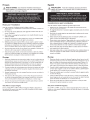
~CAUTION:
SAFETY
Before installation,
disconnect
the
battery
negative
(-)
terminal
to
prevent damage
to
the
unit, fire
and/or
possible injury.
PRACTICE SAFE
SOUND™
Continuous exposure
to
sound pressure levels over
IOOdB
may
cause permanent hearing
loss.
High powered auto sound systems
may produce sound pressure levels well over
130dB.
Use common
sense
and practice
safe
sound.
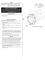
(I)
Punch Pro
Tweeter
Mounting hardware
CARTON CONTENTS
INSTALLATION
CONSIDERATIONS
Before beginning
any
installation, follow these simple rules:
I.
Be
sure
to
carefully read and understand
the
instructions before attempting
to
install these speakers.
2.
For safety, disconnect the negative
lead
from the battery prior
to
beginning
the
installation.
3. For easier assembly, we suggest you run
all
wires prior
to
mounting your speakers
in
place.
4. Use
high
quality connectors
for
a reliable installation and
to
minimize signal
or
power
loss.
5.
Think
before
you drill! Be careful
not
to
cut
or
drill into gas tanks,
fuel
lines,
brake
or
hydraulic lines, vacuum lines
or
electrical wiring when working
on
any
vehicle.
If
installation
in
a boat, take care
not
to
cut
or
drill
through
the
main
hull.
6. Never run wires underneath
the
vehicle. Running
the
wires inside the vehicle
or
hull
area provides
the
best protection.
7.
Avoid running wires over
or
through sharp edges. Use rubber
or
plastic
grommets
to
protect
any
wires routed through metal, especially the firewall.
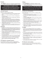
MOUNTING
I. Determine where
the
speakers
will
be mounted. Ensure
an
area large enough for
the
speaker
to
mount
evenly.
Be
sure
that
the
mounting location
is
deep enough
for
the
speaker
to
fit;
if
mounting
in
a
door
,
operate
all
functions (windows, locks,
etc.) through their entire operating range
to
ensure
there
is
no obstruction.
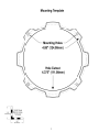
2. Refer
to
the
specification chart
to
determine
the
proper
diameter hole
to
cut
for your speaker model.
The
template provided also gives the proper
cutout
size.
3.
Mark
the
locations for
the
mounting screws. Drill
the
holes with a
1/8"
bit.
4. Feed
the
speaker wires through
the
cutout
and
connect
to
the
speaker terminals.
Be
sure
to
observe
proper
polarity when connecting
the
wires.
The
speaker's
positive terminal
is
indicated with a red
ring
.
5.
Tighten
the
screws until
the
speaker
is
snug
in
place
to
prevent rattling.
Do
not
over tighten the screws.
2
:j~
',,/~/
,
,
/ _ _ Align Holes
__
,
I
.....
_____
_
Example of standard door installation

fEATURES
ICC
(Integrated
Concealed
Crossover)
For
the
PP4-T
and
PPS-T,
the
crossover
is
integrated into
the
back cover
of
the tweeter.
This crossover
allows
for easy connection
of
the
tweeter
without the need
fo
r an external
crossover. Just connect
the
terminals
at
the
speaker,see
bel
ow
.
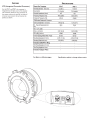
Punch
Pro
Tweeters
Nominal
Diameter-
inch
(mm)
Description
Nominal
Impedance
(ohms)
Frequency
Response
(Hz)
Crossover
Frequency
(Hz)
12dB/octave
Butterworth
Crossover
Voice
Coil
Diameter-
inch
(mm)
Fs
-
Free
Air
Resonance
(Hz)
Qts
Vas
-
cu
.
ft
.
(Liter)
Xmax-
inch
(mm)
SPL
(dB
@
1w
/1
m)
Power
Handl
i
ng-Watts
(RMS
I
Peak
)
Mounting
Diameter-inch
(mm)
Mounting
Depth-inch
(mm)
Includes
Grille/Trim
Ring
Trim
Ring
Diameter-inch
(mm)
Trim
Ring
Height-inch
(mm)
Includes
Adapter
Plate
See
figures
on
following
pages.
3
SPECIFICATIONS
PP4-T
PP8-T
1.5
(38.1)
1.5
(38
.1)
Pro
tweeter
Pro
tweeter
40
80
4kHz-20kHz
4kHz-20kHz
4.5kHz
4.
5kHz
-
-
1.475
(37
.5)
1.4
75
(37
.5)
3kHz
3kHz
-
-
-
-
0.001
(0.25)
0.
001
(0.25
)
105d8
105dB
50
/
100
50/100
4.375
(111.00
)
4.375
(111
.
00
)
2.59
(
65.8)
2.
59
(65
.8)
-
-
-
-
- -
- -
Specifications
subject
to
change
without
notice.
--- ----------
'
'
'
'

Specifications subject
to
change
without
notice.
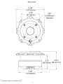
SPECIFICATIONS
5.28
11
(134.00mm)
3.45
11
(87.68mm)
4.33
11
(11
O.OOmm)
4
4.88
11
(124.00mm)
Diameter
1
2.59
11
3.24
11
(65.80mm) (82.27mm)

Fran~ais
~
MISE
EN GARDE : avant
d'entamer
!'installation,
deconnectez
Ia
•
broche
negative (-)
de
Ia
batterie
pour
eviter
tout
risque
de
blessures,
d'incendie
ou
de
dommages
a l'appareil.
PRATIQUEZ
UNE
ECOUTE
SANS
RISQUES"
0
Une exposition continue a des niveaux
de
pression acoustique superieurs
a I 00
dB
peut
causer une
perte
d'acuite auditive permanente.
Les
systemes audio
de
forte
puissance
pour
auto
peuvent produire des
niveaux
de
pression acoustique bien au-dela
de
130
dB.
Faites preuve
de
bon sens
et
pratiquez une
ecoute
sans risques
Notes
pour
!'installation
Avant de
commencer
!'installation, suivez
les
regles ci-dessous :
I.
Veillez
a bien lire
et
comprendre
les instructions avant d'essayer d'installer les
haut-parleurs.
2.
Par mesure de securite, debranchez
le
fil
negatif
de
Ia
batterie avant
de
com-
mencer
!'installation.
3.
Pour faciliter
le
montage des haut-parleurs,
il
est
conseille d'installer
tous
les
cables
au
prealable.
4.
Utilisez des
connecteurs
de
haute qualite pour assurer une installation fiable
et
reduire
au
minimum
Ia
perte
de
signal ou de puissance.
5.
Reflechissez bien avant de percer. Veillez a ne pas
couper
ou
percer
le
reser-
voir d'essence,
le
diblage electrique ou les conduites de carburant,
de
freinage
hydraulique ou
de
depression en travaillant sur
un
vehicule.
En
cas d'installa-
tion
sur
un
bateau, veillez a ne pas
couper
ou
percer
Ia
coque principale.
6.
Ne jamais faire passer
de
fils
sous
le
vehicule. Leur installation a l'interieur
du
vehicule ou de
Ia
coque assure
Ia
meilleure protection.
7.
Evitez de faire passer des
fils
sur
des bards tranchants ou dans des orifices a
aretes vives. Utilisez des bagues en caoutchouc ou en plastique
pour
proteger
les
fils
traversant une plaque
de
metal, notamment
le
tablier.
Montage
I.
Determinez !'emplacement des haut-parleurs.Veillez a ce que
Ia
surface plane soit
assez grande pour assurer
un
contact uniforme
du
haut-parleur.Verifiez que !'em-
placement
est
assez profond pour
le
haut-parleur ; en cas de montage dans une
portiere, actionnez toutes
les
commandes (fenetres, serrures, etc.) jusqu'aux
extremites de leurs courses pour vous assurer
qu'il
n'y
a
pas
d'obstruction.
2.
Consultez
le
tableau des caracteristiques pour determiner
le
diametre de !'orifice
a decouper pour votre modele de haut-parleur.
Le
gabarit fourni donne
aussi
le
bon diametre de
d<§coupe.
3.
Marquez
I'
emplacement des
vis
de montage. Percez
les
trous
avec
une meche de
1/8
de pouce (3,2 mm).
4.
Faites passer
les
fils
de haut-parleur a travers l'orifice decoupe
et
branchez-les
aux barnes
du
haut-parleur.Veillez a bien respecter
Ia
polarite lors
du
branche-
ment.
La
borne positive
du
haut-parleur est indiquee par
un
anneau rouge.
5.
Serrez
les
vis
jusqu'a ce que
le
haut-parleur soit bien ajuste, de
fa~on
a prevenir
tout
cliquetis,
mais
evitez
tout
serrage excessif.
ICC (Filtre
de
coupure
integre)
Pour
les
modeles PP4-T
et
PP8-T,
le
filtre de coupure est integre
au
haut-parleur,
si
bien
qu'aucun
filtre
externe n'est requis.
II
vous
suffit
de connecter
les
fils
du
tweeter
aux barnes
TWT
du
haut-parleur.
5
Espanol
t PRECAUCION:
Antes
de
Ia
instalaci6n,
desconecte
el terminal
~
negative
de
Ia
baterfa
(-)para
prevenir
daiio a
Ia
unidad, incendio
y/o
posibles lesiones.
~~!IIWI~~II!!IIW'-I
r~
...
I
1'\oo!UC
CL
;:)UI'IIUV
;:)E:UUftV
El
contacto continuo con niveles de presion de sonido superiores a I 00
dB
puede causar
Ia
perdida permanente de
Ia
audici6n.
Los
sistemas
de
sonido para
autom6viles
de
alta potencia pueden producir
niveles
de presion de sonido
superiores a
los
130
dB.
Use su sentido comun y practique
el
sonido seguro.
Consideraciones
para
Ia
instalacion
Antes de comenzar cualquier instalaci6n,
siga
estas simples normas:
I.
Asegurese de leer cuidadosamente y de entender
las
instrucciones antes de
tratar de
instalar estes altavoces.
2.
Por seguridad, desconecte
el
conductor negative de
Ia
baterfa antes de comenzar
Ia
instalaci6n.
3.
Para facilitar
el
montaje, sugerimos que tienda todos los cables antes de montar
sus
altavoces en
su
sitio.
4.
Utilice conectores de alta calidad para
tener
una instalaci6n confiable y para
reducir
al
minimo
las
perdidas de seiial o de potencia.
5.
jPiense siempre antes de perforar!
Tenga
cuidado de
no
cortar
ni
perforar en tan-
ques de combustible, tuberias de combustible, frenos o
hidraulicas, tuberias de
vade
o cableado electrico
al
trabajar en
un
vehiculo.
Si
Ia
instalaci6n se hace en
un
bote, tenga cuidado de no
cortar
ni
perforar a traves
del
casco principal.
6.
Nunca tienda cables abajo
del
vehiculo. Tender
los
cables ad
entre
del
vehiculo o
casco proporciona
Ia
mejor protecci6n.
7.
Evite
tender cables arriba o a traves de bordes filosos. Use arandelas aislantes de
caucho para proteger
los cables tendidos a traves de metal, especialmente
Ia
mampara cortafuegos.
Montaje
I.
Determine ad6nde se montara los altavoces.Asegurese de que
haya
un
area
sufi-
cientemente grande para montar de
man
era plana
el
altavoz. Asegurese de que
el
Iugar
de montaje sea suficientemente profunda para que quepa
el
altavoz,
si
se
menta en una puerta, accione todas
las
funciones (ventanas, cerradura, etc.) en
toda
su
gama de funcionamiento para asegurarse de que no
haya
obstrucciones.
2.
Consulte
Ia
tabla de especificaciones para determinar cuales son
los
diametros
correctos para
el
agujero a
cortar
para
su
modele de altavoz.
La
plantilla propor-
cionada tambien
le
da
Ia
medida correcta
del
recorte.
3.
Marque
las
localidades para
los
tornillos de montaje. Perfore los agujeros usando
una broca de
1/8
pulg.
4.
Tienda los cables
del
altavoz a traves
del
recorte y conecte a los terminales
del
altavoz.Asegurese de usar
Ia
polaridad correcta
al
conectar los cables.
El
terminal
positive
del
altavoz esci identificado con
un
simbolo anillo rojo.
5.
Apriete
los
tornillos hasta que
el
altavoz este ajustado en
su
sitio para evitar
vibraciones.
No
apriete demasiado
los
tornillos.
ICC
(Cruce
encubierta
integrada)
Para
el
PP4-T
y
el
PP8-T,
el
cruce es
un
diseno integral
del
altavoz. Par
lo
tanto,
nose
necesita
un
cruce externo. Simplemente conecte
los
cables
del
tweeter a
los
terminales
TWT
en
el
altavoz.

Deutsch
&.
VORSICHT:
Entfer.nen Sie
vor
dem.
~inbau
den
negative
Batteriepol,
um
Schaden
am
Gerat,
Feuer
bzw.
mogliche
Verletzungen
zu
vermeiden.
PRAKTIZIEREN
SIE
SICHEREN
SOUND
Fortgesetzte
Gerauschdruckpegel
von i.iber
I 00
dB
konnen beim Menschen zu
permanentem
Horverlust
fuhren. Leistungsstarke Autosoundsysteme konnen
Gerauschdruckpegel erzeugen, die
weit
i.iber
130
dB
liegen. Bitte wenden
Sie
gesunden Menschenverstand an und praktizieren
Sie
sicheren
Sound.
Einbauuberlegungen
Befolgen
Sie
vor
dem
Einbau diese einfachen Regeln:
I.
Lesen
Sie
die Anleitung
sorgf;iltig,
bevor
Sie
versuchen diese Lautsprecher einzubauen.
2.
Entfernen
Sie
vor
dem
Einbau
aus
Sicherheitsgri.inden
das
negative Kabel von
der
Batterie.
3.
Um
die Montage
zu
erleichtern, empfehlen
wir
aile
Kabel
vor
der
Befestigung lhrer
Lautsprecher
zu
verlegen.
4.
Yerwenden
Sie
nur
Qualiriitsstecker,
um
einen zuverlassigen
Einbau
zu
gewahrleisten
und
Signal-
und Stromverlust zu minimieren.
5.
Denken
Sie
nach,
bevor
Sie
bohren! Achten
Sie
darauf. nicht
in
den
Benzintank, die
Benzin-, Brems-
oder
hydraulischen Leitungen,Yakuumleitungen
oder
Elektrokabel
zu
schneiden
oder
zu
bohren, wenn
Sie
am
Fahrzeug
arbeiten.Achten
Sie
beim
Einbau
in
einem
Boot
darauf, nicht durch den Bootsrumpf
zu
schneiden
oder
zu
bohren.
6.
Yerlegen
Sie
Kabel nie
unter
dem
Fahrzeug.
Die Kabel im
Fahrzeug
oder
Bootsrumpf
zu
verlegen, bietet den besten Schutz.
7.
Yermeiden
Sie
es,
Kabel i.iber scharfe Kanten
zu
verlegen.Yerwenden
Sie
Gummi-
oder
Plastikringe,
um
Kabel
zu
schi.itzen, die durch Metal!
verlegt werden (besonders die
Feuerwand).
Befestigung
I.
Entscheiden,
wo
die Lautsprecher befestigt werden
sollen.
Gewahrleisten,
dass
der
Platz ausreicht, um den Lautsprecher gleichmaf3ig zu befestigen. Gewahrleisten,
dass
die Befestigungsstelle ausreichende Tiefe
fur
den Lautsprecher hat; beim Einbau in
einer
Ti.ire aile
Funktionen (Fenster,
Schloss
usw.) in ihrem ganzen Bereich auspro-
bieren
um
zu gewahrleisten,
dass
keine Blockierung
eintritt
.
2.
Die
Tabelle
in den Technischen Daten g
ibt
den richtigen Lochdurchmesser
fi.ir
lhr
Lautsprechermodell zum Ausschneiden
an.
Di
e beiliegende
Schablone
zeigt
ebenfalls
die richtige Ausschneidegrof3e
an
.
3.
Die
Stell
en
fi.ir
die Befestigungsschrauben markieren.
Die
Locher
mit
einer
I /8-Zoll
(3,2
mm)
Bohrerspitze bohren.
4.
Die
Lautsprecherkabel durch
das
Loch
fi.ihren
und
an
den Lautsprecherausgangen
anschlief3en. Beim Anschlief3en der Kabel die ordnungsgemaf3e
Polaririit
beachten.
Der
po
sitive
An
sc
hlu
ss
des Lautsprechers ist
mit
einem
rater
Ring
markiert
.
5.
Die
Schrauben anziehen, bis
der
Lautsprecher eng
an
seinem Platz anliegt,
um
Klappern zu v
er
hindern.
Die
Schrauben nicht zu f
es
t anziehen.
ICC
(lntegrierter verborgener Crossover)
Bei
den
Modellen
PP4-T und PP8-T ist
das
Crossover ein integrales Design
des
Lautsprechers. Daher
wird
ein externes Crossover nicht benotigt. Einfach die
Drahte
vom
Hochtoner
an den TWT-Anschli.i
sse
n am Lautsprecher
anschlief3en.
6
Italiano
&_
ATTENZIONE:
Prima
dell'installazione,
scollegate
il
terminale
•
negativo
(-)
della
batteria
per
evitare
danni
all'unit<i,
pericoli
d'incendio
elo
potenziali
lesioni
personali.
OSSERVATE LE REGOLE
DEL
"SUONO
SENZA
PERICOLI"
La
costante esposizione a live
ll
i
di pressione acustica al di sopra d
ei
I
OOdB
posso
no
causat-e
Ia
perdita permanente
dell'udito. I ststemi audio
ad
alta potenza
possono pr
od
u
rre
livelli di pressione acustica ben superiori
ai
130dB.
Si
consig
li
a
tl
buon senso e l'osser
vanza
delle
re
go
le
del"suo
no
senza pericoli"
Considerazioni sull'installazione
Prima
di
iniziare qualsiasi operazione d'installazione, vi consigli
amo
di seguire
queste semplici regole:
I.
Assicuratevi di aver letto tutte le istruzioni con cura e di averle capite prima di effet-
tuare
qualsiasi
tentative d'installazione neiconfronti
dell'unici..
2.
Per motivi di sicurezza,
scollegate
il
cavo
negative
dalla
batteria
pr
ima di dare
l'avvio
all'installazione.
3.
Per
facilitare
il montaggio, vi suggeriamo di far scorrere tutti i fili prima di montare
Ia
vostra
unici.
nella
sua
ubicazione.
4.
Usate connettori di
alta
qualici.
per garantire un'installazione che
da
affidamento e
per
ridurre
al
minimo
Ia
perdita di
segnali
o di potenza.
5.
State
attend prima
di
trapanare! Cercate
di
non trapanare e di non incidere i serbatoi
della
benzina;
le
condutture del carburante, dei freni, del sistema idraulico e a depres-
sione; nonche i fili elettrici quando state lavorando
su
qualsiasi
veicol
o.
6.
Non
fate
mai
scorrere i fili
sotto
il veicolo.Avrete
Ia
protezione migliore faccendo
scorrere i fili
all'interno
del
veicolo.
7.
Evitate di far scorrere i fili sopra o attraverso
delle estremici.
affilate. Usate guarnizioni
di tenuta
in
gomma o in plastica per proteggere
qualsiasi
filo che
passi
attraverso del
metallo, soprattutto
il
parafiamma.
Montaggio
I.
Decidete dove montare
gli
altoparlanti.Assicuratevi che
sia
un'area abbastanza
grande
per
peter
montare l'altoparlante a
livello
e abbastanza profonda
per
poterlo
collocare
comodamente.
Se
lo
montate
all'interno
di
uno
sportello,
control late
tutte
le funzioni (finestre, serrature, ecc.
),
una
alia
volta,
per
assicurarvi che non
ci
siano
ostru
zioni.
2.
Fate riferimento
alia tabella delle specifiche
per
stabilire
il diame
tro
corretto
del
foro
che dovrete praticare
per
il modello del vostro altoparlante.
II
modello
fornito
anche
da
Ia
dimensione adeguata del ritaglio.
3. Marcare le posizioni
per
le viti di montaggio. Praticare
i
fori
con una punta da tra-
pano di
I
/8 di pollice
(3
,2 mm).
4.
Passare
i
cavi
del diffusore
tramite
l'apertura e collegarli
ai
te
rm
in
ali.
Verificare che
Ia
polarici.
sia
corretta
quando
si
collegano
i
cavi.
II
terminale positive del diffusore
e
identificato dal
anello
ro
ss
o.
5.
Per evitare
rumore
dovuto a vibrazioni serrare le viti finche il diffusore
non
sia
sa
lda-
mente in posizione.
Non
serrare
le
viti in
modo
eccessivo.
ICC
(Crossover celato
integrato)
Per progettazione, il crossover del PP4-T e del PP8-T
e
incorporate
nel diffusore.
P
ertanto
non
si
richiede
l'uso
di un crossover es
terno
.
Ba
sta
collegare
i fili provenienti
dal
tw
ee
ter
ai
terminali
TWT
sui diffusore.

Verify
Scale
1.00"
Before Using
(
25
·
40
mm)
Template
Mounting
Template
Mounting
Holes
4.88"
(124.00mm)
Hole
Cutout
4.375"
(111.00mm)
7

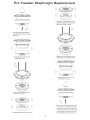
Pro
Tweeter
Diaphragm
Replacement
Q
I, Hold
the
phase
plug firmly,release
screw
from back
of
motor
to
remove
phase
plug.
2,
Disconnect the connectors and
remove
motor
cover.
3,
Unscrew
the
screws from housing
to
remo
ve
it
fr
om
motor
.
4,
Lift
di
aphragm/co
il
assembly
from m
oto
r.
8
5,
Take
out
new diaphragm/coil
assemly,
align
holes
in
plastic
with rivets on
top
plate and fit
to
motor
carefully.
6,
Align
the
pins
on
housing with
holes
in
plastic
then secure housing with screws.
7,
Align
c
onn
ecto
rs
in
motor
cov
er
with
tweeter
and fit
co
ver.
Q
' 1
8, Fit the
screw
with
fla
t wash
er
from
mo
tor
cover,make sure
screw
tip
exten
ds above
di
aphragm,
the
n
caref
ully
fit the
ph
ase
plug
from front and move
the
screw back a
little
until
ph
ase
plu
g
sits
in
pole pi
ece
. Ho
ld
th
e
phase
p
lu
g
fi
r
mly
and sec
ur
e it with
screw
.

LIMITED WARRANTY
STATEMENT
Rockford Corporation offers a limited warranty on Rockford Fosgate products
on
the
following
terms:
Length
ofWarranty
Speakers-
I
Year.
Any Factory Refurbished
Product-
90 days (receipt required)
What
is
Covered
This warranty applies only
to
Rockford Fosgate products sold
to
consumers
by
Authorized Rockford Fosgate
Dealers
in
the
United States of America
or
its possessions. Product purchased
by
consumers from
an
Authorized Rockford Fosgate Dealer
in
another
country are covered only
by
that country's Distributor and
not
by
Rockford Corporation.
Who
is
Covered
This warranty covers only
the
original purchaser of Rockford product purchased from
an
Authorized
Rockford Fosgate Dealer
in
the
United States.
In
order
to
receive service,
the
purchaser must provide
Rockford with a copy of
the
receipt stating
the
customer name, dealer name, product purchased and date of
purchase. Products found
to
be defective during the warranty period
will
be repaired
or
replaced
(with a product deemed
to
be equivalent)
at
Rockford's discretion.
What
is
Not
Covered
I
. Damage caused
by
accident, abuse, improper operations, water,
theft,
shipping
2.Any
cost
or
expense related
to
the
removal
or
reinstallation of product
3.
Service performed
by
anyone
other
than Rockford
or
an
Authorized Rockford Fosgate Service
Center
4.Any product which has had
the
serial number defaced, altered,
or
removed
5.
Subsequent damage
to
other
components
6.Any product purchased outside
the
U.S.
?.Any product
not
purchased from
an
Authorized Rockford Fosgate Dealer
Limit
on
Implied Warranties
Any
implied warranties
including
warranties of fitness for use and merchantability are limited
in
duration
to
the
period of the express warranty set forth above. Some
states do not
allow limitations on the length of
an
implied
warranty, so this limitation
may
not
apply.
No
person
is
authorized
to
assume for Rockford Fosgate
any
other
liability
in
connection with the sale of the product.
How
to
Obtain Service
Contact
the
Authorized Rockford Fosgate Dealer you purchased this product from.
If
you need further
assistance,
call
1-800-669-9899
for Rockford
Customer
Service.You must obtain
an
RA#
(Return
Authorization
number)
to
return any product
to
Rockford Fosgate.
You
are responsible for shipment
of product
to
Rockford.
EUWarranty
This product meets the current
EU
warranty requirements, see your Authorized dealer for details.
1230-57459-0 I
Rockford
Fosgate
Rockford
Corporation
600 South
Rockford Drive
Tempe, Arizona
85281
U.S.A.
In
U.S.A., (480) 967-3565
Customer
Service
1-800-669-9899
www.rockfordfosgate.com
© 20
12
Rockford
Corporation.
All
rights reserved.
Rockford Fosgate and
the
Rockford Fosgate logo
are
either
registered
trademarks
or
trademarks
of
Rockford
Corporation.
Printed in China
-
 1
1
-
 2
2
-
 3
3
-
 4
4
-
 5
5
-
 6
6
-
 7
7
-
 8
8
-
 9
9


Rockford Fosgate Punch PP8-T Installation & Operation Manual
- Tipo
- Installation & Operation Manual
- Questo manuale è adatto anche per
in altre lingue
- English: Rockford Fosgate Punch PP8-T
- français: Rockford Fosgate Punch PP8-T
- español: Rockford Fosgate Punch PP8-T
- Deutsch: Rockford Fosgate Punch PP8-T
Documenti correlati
-
 Rockford Fosgate PUNCH PM2T-S Installation & Operation Manual
-
 Rockford Fosgate T4652-S Installation & Operation Manual
-
Rockford Fosgate T165-S Installation & Operation Manual
-
Rockford Fosgate T1 T-S Installation & Operation Manual
-
Rockford Fosgate power T252-S Installation & Operation Manual
-
Rockford Fosgate Punch P152-S Installation & Operation Manual
-
Rockford Fosgate Punch P152 Installation & Operation Manual
-
Rockford Fosgate PUNCH PPS8-6 Manuale del proprietario
-
Rockford Fosgate PRIME R1653 Installation & Operation Manual
-
Rockford Fosgate M282-Wake Installation & Operation

