
§
•
•
MARINE
GRADE
M2
-
WAKEBOARD
TOWER
SPEAKERS
6.5''
M262-WAI<E
a··
M282-WAI<E
M2628-W
AI<E
M2828-W
AI<E
Installation
&
Operation
Serial
Number:
Date
of
Purchase:
------
---

SAFETY
~CAUTION:
Before
installation,
disconnect
the
battery
•
negative (-)
terminal
to
prevent damage
to
the
unit, fire
and/or
possible
injury.
PRACTICE
SAFE
SOUND™
Continuous
exposure
to
sound
pressure
levels
over
I
OOdB
may
cause
permanent
hearing
loss.
High
powered
auto
sound
systems
may
produce
sound
pressure
levels well
over
130dB.
Use
common
sense
and
practice
safe
sound.
CARTON
CONTENTS
(I)
Set
Marine Grade
M2
Wakeboard Tower Speakers
(I)
Set
of
adjustable swivel
clamps
(I)
Allen
head wrench
(I)
Mol
ex speaker harness
(I)
Set
of
rubber inserts for
I 1/2"
-
I
3/4"
applications
(I)
Set
of
rubber inserts for
I 7/8" -
2
3/4"
applications
INSTALLATION
CONSIDERATIONS
Before beginning any
installation, follow
these simple rules:
I.
Be
sure
to
carefully read
and understand
the
instructions before attempting
to
install
these speakers.
2.
For safety, disconnect
the
negative lead from
the
battery prior
to
beginning
the
installation.
3.
For easier assembly, we suggest you run
all
wires prior
to
mounting your speakers
in
place.
4. Use
high
quality connectors for a
reliable installation
and
to
minimize
signal
or
power loss.
5.
Think
before
you
drill!
Be
careful
not
to
cut
or
drill
into
gas
tanks,
fuel
lines,
brake
or
hydraulic
lines,
vacuum lines
or
electrical wiring when working
on
any
vehicle.
If
installation
in
a boat, take care
not
to
cut
or
drill
through
the
main
hull.
6. Never run wires
in
the
open area of
the
boat. Running the wires inside
the
wake-
board
tower
and
hull
area provides
the
best protection.
7. Avoid running wires over
or
through sharp edges. Use rubber
or
plastic
grommets
to
protect any wires routed through metal.
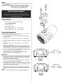
MOUNTING
I.
Determine
where
the
speakers
will
be mounted.
Be
sure
that
the
mounting loca-
tion has sufficient
clearance
in
all
directions for
the
speaker
to
swivel; conduct a
full
rotation
to
ensure there
is
no obstruction.
2. Mark
the
locations on
the
underside
of
the
clamping
surface for
the
speaker har-
ness
to
be feed through.
Drill
the holes with a 3/8" bit.
3. Feed
the
speaker wires through
the
hole and connect
to
the speaker harness.
Be
sure
to
observe proper polarity when connecting
the
wires. The speaker harness's
negative wire
is
indicated with a "black-stripe".
4. Feed
the
speaker
harness through
the
center
of
the
base of
the
clamp.
Fit
the
clamp
to
the mounting area and tighten
the
bolts evenly with
the
supplied
allen
wrench.
NOTE:
Use the proper rubber insert for the corresponding
clamping
diameter.
i
I
I
Adjusts to fit
1 1
/2"
---
1
3/4"
(3.
81
em) (4.45cm)
Adjusts
to
fit
1 7/8"
---
2
3/4"
(4.76cm) (6.99cm)
l

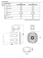
PHYSICAL
DIMENSIONS
MARINE
GRADE
M2
6.5
11
811
M262-WAKEIM262B-WAKE M282-WAKE/M282B-WAKE
A-
Overall height-inch
10.96
13.14
(em)
(27.83) (33.37)
B-
Overall length-inch
11.26 13.10
(em)
(28.59) (33.25)
C-
Overall diameter-inch
7.03
9.05
(em) (I
1.85)
(23.00)
D-
Clamp
Range-inch
1.5
to
2.75
1.5
to
2.75
(em)
(3
.
81
to
6.99)
(3
.
81
to
6.99)
Mass
(Weight) -
lbs.
6.20
8.80
(kg)
(2.80) (4.00)
Power handling·watts
(RMS)
75
100
(Peak)
(ISO)
(200)
Specifications
subject
to
change
without
notice
: ]
A
c
c:::
l
3

Fran~s
A\
MISE
EN
GARDE:
Avant d'entamer
l'install~tion,
deconnectez
Ia
broch~
negative
(-)
de
Ia
~
battene
pour
ev1ter
tout
nsque
de
blessures, d
1ncend1e
ou
de
dommages a
l'appareil.
PRATIQUEZ
UNE
ECOUTE
SANS
RISQUES
Une
exposition
contmue
a
des
mveaux
de
press1on acoust1que
supeneurs
a
I
00
dB
peut
causer une
perte
d'acUJte
aud1t1ve
permanence
Les
systemes audio de
forte
puiSsance
pour
auto
peuvent
p10dU1re
des
n1veaux
de
presSion
acoust
1
que
b1en
au-
dela
de
130
dB
Fa~tes
preuve
de
bon
sens
et
prat1quez
une
ecoute
sans
mques
Considerations
d'installation
Avant
de
commencer
toute
installation,
suivre ces
simples
regles:
I.
S'assurer
de
lire
attentivement
et
de
comprendre
les
instructions
avant
d'essayer
d'in-
staller ces enceintes.
2.
Par
mesure
de
securite,
deconnecter
le
fil
negatif
de
Ia
batterie
avant
de
commencer
!'in-
stallation.
3.
Pour
faciliter !'assemblage,
il
est
recommande
d'acheminer
tous
les
fils
avant
de
monter
les
enceintes
en
place.
4.
Utiliser
des
connecteurs
de
haute
qualite
pour
une
installation
liable
et
pour
minimiser
Ia
perte
de
signal
ou
de
puissance.
5.
Reflechir
avant
de
percer!
Faire
attention
de
ne
pas
couper
ou
percer
dans
les
reservoirs
d'essence,
les
conduites
de
carburant,
les
conduites
de
frein
ou
hydrauliques,
les
!ignes
de
vide
ou
le diblage
electrique
lors
de
tout
travail
sur
un
vehicule.
Pour
une
installation
dans
un bateau, faire
attention
de
ne
pas
couper
ou
percer
a
travers
Ia
coque
principale.
6.
Ne
jamais
acheminer
de
fils
dans
Ia
zone
ouverte
d'un
bateau
.
Acheminer
les fils
a
l'in-
terieur
de
Ia
tour
de
remorquage
et
de
Ia
coque
offre
Ia
meilleure
protection
possible.
7. Eviter
d'acheminer
les
fils
sur
ou
a
travers
des
chants
coupants.
Utiliser
des
passe-dibles
en
caoutchouc
ou
en
plastique
pour
proteger
tout
fil
achemine
a
travers
le metal.
Montage
I.
Determiner
l'
endroit
de
montage
des
enceintes
.
S'assurer
que
I'
emplacement
de
montage
a suffisamment
de
degagement
dans
tous
les
sens
pour
que
I'
enceinte
puisse
pivoter;
exe-
cuter
une
rotation
complete
pour
s'assurer
qu'il n'y pas d'
obstruction
.
2.
Marquer
les
emplacements
sur
le
dessous
de
surface
de
serrage
pour
alimenter
le fais-
ceau
de
I'
enceinte.
Percer
les
trous
avec
un
trepan
3/8".
3.
Alimenter
les fils
d'enceinte
a
travers
le
trou
et
connecter
au faisceau
d'enceinte
.
S'assurer
d'observer
Ia
polarite
appropriee
lors
de
Ia
connexion
des
fils. Le harnais
de
haut-parleur
le til
negatif
est
indique avec
une
<<noir-piste».
4.
Alimenter
le
faisceau
d'enceinte
a
travers
le
centre
de
Ia
base
de
Ia
pince.
Mettre
Ia
pince
sur
Ia
surface
de
montage
et
serrer
les
boulons
uniformement
a
I'
aide
de
Ia
cle Allen
fournie.
REMARQUE:
Espanol
Utiliser
!'insert
en
caoutchouc
approprie
pour
le
diametre
de
pince
cor-
respondant
.
A\
PRECAUCI6N:
Antes
de
Ia
instalaci6n,
desconecte
el
terminal negative
de
Ia
bateria
(-)
~
para prevenir
daiio
a
Ia
unidad, incendio
y/o
posibles lesiones.
PRACTIQUE
EL
SONIDO
SEGURO
El
contacto connnuo con
mve
les
de
p1
es
1
on
de
son
1do
su
pe
nor
es
a
I 00
dB
puede
causar
Ia
pe1
d1da
permanence
de
Ia
aud1c1on
L
os
SISt
emas
de
son1
do
para
automov
1l
es
de alta
potcnc1a
pueden
producw
nw
e!es
de
pr
es1
on
de
so
ntdo
supenores
a
l
os
1
30
dB
Usc
su
sentldo
comun
y
pract1qu
e el
so
mdo
seg
uro
Conslderaciones
para
Ia
instalaci6n
Antes
de
comenzar
cualquier instalaci6n, siga
estas
simples
normas
:
I. Aseg\Jrese
de
leer
cuidadosamente y
de
entender
las
instrucciones
antes
de
tratar
de
instalar
estes
altavoces.
2.
Per
seguridad,
desconecte
el
conductor
negative
de
Ia
baterfa antes
de
comenzar
Ia
insta-
laci6n.
3. Para
facilitar
el
montaje, sugerimos
que
tienda
todos
los
cables
antes
de
montar
sus altavoces
en
su
sitio.
4.
Utilice
conectore
s
de
alta calidad
para
tener
una instalaci6n confiable y
para
reducir
al
mini-
me
las
perdidas
de
senal
o
de
potentia
.
5.
;Piense
siempre
antes
de
perforar! Tenga cuidado
de
no
cortar
ni
perforar
tanques
de
com-
bustible, tuberfas
de
combustible,
de
frenos o hidriulicas,
tuberfas
de
vacio o cableado
elec-
trico
al
trabajar
en
cualquier vehiculo.
Si
Ia
instalaci6n
se
hace
en
una
embancaci6n, tenga
cuidado
de
no
cortar
ni
perforar
a
craves del
casco
principal.
6.
Nunca
tienda
los cables en el
area
abierta
de
una
embancaci6n.Tender
los
cables
adentro
de
Ia
terr
e
para
esquf y el a
rea
del casco proponciona
Ia
mejor
protecci6n
.
7. Evite
tender
cables
arr
iba o a traves
de
bordes
filosos.
Use
arandelas
de
caucho
o
plastico
para
proteger
los cables
tendidos
a traves
de
metal.
Montaje
I.
Determine
ad6nde
se
montarin
los
altavoces.Asegurese
de
que
Ia
localidad
de
montaje
tenga
suficiente espacio libre
en
tod
as
las
direcciones
para
que
el altavoz bascule,
hagalo
dar
toda
una
vuelta
para
asegurarse
de
que
no
haya
obstrucciones
.
2. Marque
Ia
localidad
del
lade
de
abajo
se
Ia
superficie
de
fijaci6n para
hacer
pasar el
ames
del
altavoz.
Perfore los
agujeros usando una
broca
de
3/8
pulg.
3.
Tienda
los
cables del altavoz a traves
del
agujero y
conecte
al
ames
del altavoz.Aseg\Jrese
de
usar
Ia
polaridad
corr
ecta
al
conectar
los
cables.
El
harn
es
s
del
altavoz
el
alambre negati
ve
se
indica
con
una
u
negro
-ra
ya
".
4.
Alimente
el a
mes
del altavoz a
tra
v
es
del
ce
ntro
de
Ia
base
de Ia abrazade
ra
. Calce
Ia
abrazadera
al
area
de
montaje
y apriete
los
pe
rnos
de
manera
uniforme
con
Ia
ll
ave
Allen
pnoponcionada.
NOTA:
Use
el
inserto
de
caucho
correcto
para
el
diametro
de
fijaci6n
con
abrazadera
corre-
spondiente.
4
Deutsch
A\
VOI:tSICHT:
Entfemen Sie vor
dem
Einbau
den
negative Batteriepol, um Schiiden am
~
Gerat, Feuer bzw. mogliche Verletzungen zu vermeiden.
PRAKTIZIEREN SIE SICHEREN
SOUND
Fortgesetzte Gerauschdruckpegel von u
ber
I
00
dB konnen be
1m
Menschen zu
permanen·
tern
Hor
ve
rlust fuhren. LeiStungsstarke Autosoundsysteme kon
nen
Ge
rauschdruckpegel
erzeugen.
d1e
welt
uber
130
dB hegen
B1tte
wenden
S1e
gesunden Menschenverstand an
und
prakt
1z
1
eren
S1e
siCheren Sound
Elnbaui.iberlegungen
Befolgen
Sie
vor
dem
Einbau
diese
einfachen Regeln:
I.
Lesen
Sie
die Anleitung
sorgf.iltig,
bevor
Sie
versuchen diese Lautsprecher einzubauen.
2 Entfernen
Sie
vor
dem
Einbau
aus
Sicherheitsgriinden das
negative
Kabel
von
der
Batterie.
3.
Urn die Montage zu erleichtem, empfehlen wir alle Kabel
vor
der
Befestigung lhrer Lautsprecher zu
verlegen.
4.
Verwenden
Sie
nur
Qualit:iitsstecker,
um einen
zuverliissigen
Einbau
zu
gewiihrleisten
und
Signal-
und
Stromverlust
zu minimieren.
5. Denken
Sie
nach, bevor
Sie
bohren! Achten
Sie
darauf, nicht
in
den Benzintank, die Benzin-. Brems-
oder
hydraulischen Leitungen,Vakuumleitungen
oder
Elektrokabel zu schneiden
oder
zu bohren,
wenn
Sie
am Fahrzeug arbeiten.Achten
Sie
beim Einbau
in
einem Boot darauf, nicht dunch den
Bootsnumpf zu schneiden
oder
zu bohren.
6. Verlegen
Sie
Kabel
niemals
in
einem
oirenen
Bereich des Boots. Die Kabel im lnneren
des
Wakeboard-
Tower
oder
Bootsnumpfs zu verlegen,
bietet
den besten
Schutz.
7.
Vermeiden Sie
es,
Kabel
iiber
scharie
Kamen
zu verlegen.Verwenden Sie Gummi-
oder
Plastikringe,
um
Kabel
zu schiitzen, die dunch
Metall
verlegt wenden.
Befestigung
I.
Entscheiden,
wo
die Lautsprecher befestigt
werden
sollen. Dunch eine voile Rotation
des
Lautsprechers
gewiihrleisten,
dass die Befestigungsstelle
in
aile
Richtungen ausreichenden
Spielraum zum Schwenken bietet;
2. Die
Stellen
an
der
Unterseite
der
Klammerungsoberfliiche markieren, an
denen
der
Kabelbaum
dunchgefuhrt wenden soil. Die
Li:icher
mit
einer
3/8-Zoll (3,2 mm) Bohrerspitze bohren.
3. Die Lautsprechendriihte dunch das Loch fuhren
und
an den Lautsprecher-Kabelbaum
anschlieBen. Beim AnschlieBen
der
Kabel die ondnungsgemiiBe
Polarit:iit
beachten.
Des
Sprechergeschirrs negativer
Draht
wird
mit
einem ,Schwarzstreifen" angezeigt.
4.
Den
Lautsprecher-Kabelbaum dunch die Mitte
am
FuB
der
Klammer
fUhren.
Die Klammer an
die Befestigungsstelle anpassen und die Bolzen mit
dem
beiliegenden
lnbusschliissel gleichmiiBig
anziehen
.
HINWEIS:
Den
dem
jeweiligen
Klammerdurchmesser
entsprechenden
Gummieinsatz
ver-
wenden
.
Italiano
A\
ATTENZIONE:
Prima dell'installazione, scollegate
il
terminale negative (-) della
bacteria
~
per
evitare danni
all'unira,
pericoli d'incendio
e/o
potenziali lesioni personali.
OSSERVATE
LE
REGOLE DEL
SUONO
SENZA
PERICOLI
La
costante
e
spoSIZ
ione a
l1
vell1
d1
pres
Sion
e
ac
ustiCa
al
d1
sopr
a
de1
I
OOdB
possono
causare
Ia
per
d1
ta p
er
manence
d
ell"ud1tO
I
S1St
em
1 au
d1
o
ad
alt.1
potenza
possono
produrre
li
ve
ll1 d1 p
ress
1on
e
ac
u
st!Ca
ben supenon
a1
130dB
S1
cons
1
gha
1l
b
uon
senso
e
l'
osse
rv
anza
de
ll
e
regale
de
l s
uono
se
nza pencoh
Conslderazioni
sull•installazione
Prima
di iniziare un'installazione qualsiasi
osservare
le
semplici indicazioni seguenti:
I.
Accertarsi
di
leggere e comprendere
tutte
le istruzioni prima
di
tentare
d'installare
questi
difl"usori
.
2
Per
ragioni
di
sicurezza,
scollegare
il
conduttore
negative della bacteria
prima d'iniziare
l'instal-
lazione.
3.
Per
facilitare
il
montaggio. consigliamo
di
predisponre
tutti i
fili
in
loco prima
di
fissare i diffusori
in
posizione.
4.
Per
ottenere
un'istallazione
affidabile,
con
pendita minima
di
segnale o
potenza,
usare connettori
d'alta
qualita.
5.
Pensarci prima
di
fare
fori
col
trapano!
Quando
si
lavora
su un
veicolo,
fare sempre attenzione a
non intaccare o praticare fori
nel
serbatoio e nei tubi
della
carburante.
nei
tubi idraulici o
in
quelli
dei
fTeni,
nei
rubi
sottovuoto e nelle linee dell'impianto
elettrico.
Quando
si
installa su una imbar -
cazione, prestare attenzione a
non
lllgiiare
o perforare
lo
scafo
principale.
6.
In
una imbarcazione, non stendere
mai
i
fili
in
un'area
aperta.
Stendendo i
fili
all'intemo
della
terre
per
wakeboand
e dell' area delle
scafo
si
ottiene
Ia
pnotezione
migliore.
7.
Evitare
di
far
passare
i
fili
su o attraverso bondi
lllgiienti.
Usare guamizioni
di
gamma
o
di
plastica
pe
r proteggere i
fili
che attraversano
pareti
metalliche.
lnstallazlone
I.
2.
3.
4.
Stabilire
in
quale
posizione
montare
i diffusori.Accertarsi
che
il
peste
s
ce
lto abbia spazio suffi-
ciente
in
tutte
le
direzioni
per
consentire
al
diffusore di
ruota
re
lib
eramente;
ruotare
il
diffusore
di un giro
complete
per
accertarsi che
non
ci
sono
ostacoli.
Marcare sui late inferiore della superficie di fissaggio
le posizioni
per
fare passare
il
cablaggio
del
diffusore.
Praticare i fori
con
una punta da
trapano
di
3/8 di
pollice
(3,2 mm)
Passare i
fili
del
diffusore nel fono e collegarli
al
cablaggio
del
diffusore.
Quando
si
esegue
Ia
con-
nessione, accertarsi
di
osservare
Ia
polari
ta
corretta
.
II
cablaggio dell'
alto
parlante
il
cave negative
e
indicate
con
"una nero-banda.,.
lnfilare
il
cablaggio
del
diffusore attraverso
il
centro
della base
del
morsetto.Ada
ttare
il
mors
et
-
to
all' area
di
montaggio
·e
serrare
i bulloni
in
modo
uniforme servendosi
dell.a
chiave
pe
r viti
All
en.
NOTA:
Usar
e
l'ins
erto
di
ge
mma
ada
tt
o
al
diametro
corrispondente
del
mors
etto
.

LIMITED
WARRANTY
STATEMENT
Rockford Corporation offers a limited
warranty on Rockford Fosgate products on
the
following terms:
Length
of
Warranty
Speakers
-
I
Year.
Any
Factory
Refurbished
Product
-
90
days
{receipt
required)
What
Is
Covered
This warranty applies only
to
Rockford Fosgate products
sold
to
consumers
by
Authorized Rockford Fosgate
Dealers
in
the
United States
of
America
or
its possessions. Product purchased
by
consumers from an
Authorized Rockford Fosgate Dealer
in
another country are covered
only
by
that country's Distributor and
not
by
Rockford Corporation.
Who
is
Covered
This warranty covers
only
the
original purchaser of Rockford product purchased from
an
Authorized
Rockford Fosgate
Dealer
in
the
United States.
In
order
to
receive service,
the
purchaser must provide
Rockford with a copy of
the
receipt stating
the
customer name,
dealer
name, product purchased and date of
purchase. Products found
to
be defective during
the
warranty period
>vyill
be repaired
or
replaced
(with a product deemed
to
be equivalent)
at
Rockford's discretion.
What
is
Not
Covered
I.
Damage caused
by
accident, abuse, improper operations, water, theft, shipping
2.
Any
cost
or
expense
related
to
the
removal
or
reinstallation
of
product
3.
Service performed
by
anyone
other
than Rockford
or
an
Authorized Rockford Fosgate Service
Center
4.
Any
product which has had
the
serial number defaced,
altered,
or
removed
5.
Subsequent damage
to
other
components
6.
Any product purchased outside the
U.S.
7.
Any product
not
purchased from
an
Authorized Rockford Fosgate
Dealer
Limit
on
Implied
Warranties
Any
implied
warranties
including
warranties of fitness for use and merchantability
are
limited
in
duration
to
the
period of the express warranty set forth above. Some states do not
allow limitations
on the
length
of
an
implied
warranty, so this
limitation
may
not
apply.
No
person
is
authorized
to
assume for Rockford Fosgate
any
other
liability
in
connection
with
the
sale
of the product.
How
to
Obtain
Service
Contact
the
Authorized Rockford Fosgate
Dealer you purchased this product from.
If
you need further
assistance,
call
1-800-669-9899
for Rockford
Customer
Service.
You
must obtain an
RA#
(Return
Authorization
number)
to
return
any
product
to
Rockford Fosgate.You are
responsible
for shipment
of product
to
Rockford.
E.U
Warranty
This product meets
the
current
EU
warranty requirements, see your Authorized dealer
for
details.
Check
our
website
for
additional
information
and
updates
on
these
products.
www.RockfordFosgate.com
©20
12
Rockford
Corporation.
All
Rights Reversed.
ROCKFORD FOSGATE
and associated
logos
where
applicable
are
registered
trademarks
of
Rockford
Corporation
in
the
United States
and/or
other
countries.
All
other
trademarks
are
the
property
of
their
respective
owners.
Specifications subject
to
change
without
notice.
1230-57454-03
Printed in China
-
 1
1
-
 2
2
-
 3
3
-
 4
4
-
 5
5


Rockford Fosgate M282-Wake Installation & Operation
- Tipo
- Installation & Operation
- Questo manuale è adatto anche per
in altre lingue
- English: Rockford Fosgate M282-Wake
- français: Rockford Fosgate M282-Wake
- español: Rockford Fosgate M282-Wake
- Deutsch: Rockford Fosgate M282-Wake
Documenti correlati
-
 Rockford Fosgate T4652-S Installation & Operation Manual
-
Rockford Fosgate PUNCH PPS8-6 Manuale del proprietario
-
Rockford Fosgate PRIME R1653 Installation & Operation Manual
-
 Rockford Fosgate Punch PP8-T Installation & Operation Manual
-
Rockford Fosgate power T252-S Installation & Operation Manual
-
 Rockford Fosgate PUNCH PM2T-S Installation & Operation Manual
-
Rockford Fosgate Punch P152 Installation & Operation Manual
-
Rockford Fosgate T165-S Installation & Operation Manual
-
Rockford Fosgate T1 T-S Installation & Operation Manual
-
Rockford Fosgate PM282HW-B Manuale utente


