Rockford Fosgate T4652-S Installation & Operation Manual
- Categoria
- Altoparlanti per auto
- Tipo
- Installation & Operation Manual

I
)
vv
E
Component
Systems
T4652-S
-
6.5''
Serial
Number:
------
Installation
&
Operation
Installation
et
fonctionnement
lnstalacion
y
funcionamiento
Einbau
und
Betrieb
lnstallazione
e
funzionamento
Date
of
Purchase:
------

SAFETY
CAUTION:
Before
installation,
disconnect
the
battery
negative
(-)
terminal
to
prevent damage
to
the
unit, fire
and/or
possible injury.
Lt.
PRACTICE
SAFE
SOUND™
Continuous
exposure
to
sound
pressure
levels
over
I
OOdB
may
cause
permanent
hearing
loss.
High
powered
auto
sound
systems
may
produce
sound
pressure
levels well
over
130dB.
Use
common
sense
and
practice
safe
sound.
CARTON CONTENTS
(1)
Set
T4
Series
Speakers
with
Tweeters
and
2-Way
Cros
s
overs
•
(1)
Set
of
grilles/trim rings
(1)
Set
of
tweeter
trim
rings
Tweeter Mounting
Hardware
with
Surface,
Angle,
and
Flush
Mounts
INSTALLATION CONSIDERATIONS
Before
beginning
any
installation, follow
these
simple rules:
I.
Be
sure
to
carefully read and understand the instructions before attempting
to
install
these speakers.
2. For safety, disconnect the negative
lead
from the battery prior
to
beginning
the
in
stallation.
3.
For easier
assembly,
we
suggest
you
run
all
wires prior
to
mounting your speakers
in place.
4. Use
high
quality
connectors for a
reliable
installation and
to
minimize
signal
or
power
loss.
5.
Think
before
you
drill!
Be
careful
not
to
cut
or
drill
into gas tanks,
fuel
lines,
brake
or
hydraulic
lines,
vacuum
lines
or
electrical
wiring when working
on
any
vehicle.
If
installation
in
a boat, take care
not
to
cut
or
drill
through
the
main
hull.
6. Never run wires underneath the
vehicle.
Running
the wires inside
the
vehicle
or
hull
area provides the best protection.
7.
Avoid
running wires over
or
through sharp edges. Use rubber
or
plastic
grommets
to
protect any wires routed through
metal, especially
the
firewall.
2
I.
MouNTING
Determine where the speakers
will
be mounted. Ensure
an
area
large
enough for
the speaker
to
mount
evenly.
Be
sure that the mounting
location
is
deep enough
for the speaker
to
fit;
if
mounting
in
a door, operate
all
functions (windows,
locks,
etc.) through their entire operating range
to
ensure there
is
no obstruction.
2.
Refer
to
the specification chart
to
determine the proper diameter
hole
to
cut
for your speaker
model.
The
template
provided
also
gives
the proper cutout size.
3.
Mark
the
locations
for the mounting screws.
Drill
the holes
with a
1/8"
bit.
4.
Feed
the
speaker wires through
the
cutout and connect
to
the
speaker terminals.
Be
sure
to
observe proper
polarity
when connecting the wires. The speaker's
positive
terminal
is
indicated with a
"+".
5.
On models
with
slotted holes,
fit
the speaker into the cutout and
install
the
screws
in
the slots
at
the top and bottom. This
will
allow
you
to
rotate
the
speak-
er
to
match the remaining mounting
holes.
When
aligned,
tighten the screws.
6. Tighten the screws
until
the
speaker
is
snug
in
place
to
prevent
rattling.
Do not
over tighten the screws.
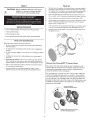
Discreet
Dual
Clamp
(DOC™)
Tweeter
Mount
Every
aspect
of
the
new
Tweeter
design
has
been
completely
re-engi-
neered
to
allow
for
maximum
ease
of
installation
and
fitment.This
opti-
mized
patent
pending
design
provides
concentric
clamping
pressure
around
the
perimeter
of
the
mounting
hole
.
The
"mounting
cups"
are
in
fact
not
"cups"
at
all,
but
rather
unobtrusive
"clamps
"
th
at
quickly
and
easily
mount
in
a
standard
1.75
inch
(45mm)
hole
saw
opening
with
a
single
center
screw
securing
with
balanced
pres-
sure
to
both
faces
of
the
mounting
surface.
From
there,
the
tweeter
sim-
ply
snaps
into
place
and
is
secured
by
a
snap-on
trim
ring.
Removal
is
easy
if
needed.
The
protective
grille
on
the
tweeter
is
non-removable
and
an
intergral
part
of
the
design.
Use
tip
of
a
small
flat
screwdriver
to
remove
tweeter
Example
of
Discreet
Dual
Clamp
(DDCTM)
Tweeter
Mounting
(Flush Mount}

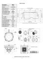
SPECIFICATIONS
T 4
Components
T4652-S
Nominal
Diameter-
inch
(mm)
6.5
(165)
Description
Component
System
Nominal
Impedance
(ohms)
Frequency
Response
(Hz)
Crossover
Frequency
(Hz)
High
-
Pass
Butterworth
Crossover
Low
Pass
Butterworth
Crossover
Voice
Coil
Diameter-
inch
(mm)
Fs
-
Free
Nr
Resonance
(Hz)
Qts
Vas
-
cu.
ft.
(Liter)
Xmax-
inch
(mm)
SPL
(dB@
1w/1m)
Power
Handling-Watts
(RMS
I
Peak)
Rec.
Amp
Power-Watts
(RMS)
Mounting
Diameter-inch
(mm)
Mounting
Depth-inch
(mm)
Includes
Grille/Trim
Ring
Trim
Ring
Diameter-inch
(mm)
Trim
Ring
Height-inch
(mm)
Woofer
6.69"
(170mm)
0
5.67"
(144mm)
40
40Hz-
30kHz
3kHz
12dB/octave
12dB/octave
1.5
(38)
52
0.58
0.59
(16.74)
0.5
(12.6)
89dB
150/300
37.5W-150W
5.
67
(144)
2.79
(71)
YES
7.14
(181)
0.95
(24)
6.18"
(157mm)
Diam
eter
3.22"
(82
mm)
10
10
-on-
Ax
is
100
100
SPL
(1
W1
M)
• Impedance
-
30-D
eg
Off
Axis
1000
1000
Frequency (Hz)
- Impedance
10000
10000
Frequency responce
includes
summed
Far
-F
ield
and
Near-Field IEC60268-5 baffle
measurements.
Tweeter Mounting Options
Surface
Mount
4.57"
1--
--
(116mm) _ _
......._,
4.09"
f--
--
(104mm)
--
.j
Component Crossover
Specifications
subject
to
change
without
notice.
3
100000

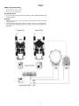
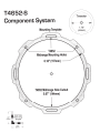
T4652-S Component
Wiring
I.
Use
illustration for
proper
connection.
2.
Be
sure
to
maintain speaker
polarity.
Axis
ON-OFF
Switch
WIRING
I.
Set
to
ON
or
OFF
to
match position
of
tweeter
relative
to
listener. Default
OFF
position satis-
fies most installations.
dB
Switch
I.
OdB
matches
the
amplitude
(no increase/no attenuation) of
the
tweeter
to
the
same
level as
the
mid-range (woofer).
2.
+2dB increases and -2dB reduces
the
amplitude
of
tweeter
in
relation
to
the
mid-range, (ideal
when matching offset
installation l
ike
tweeters
located
high
in
door
panels
and midranges
low
in
kick panels).
Tweeter
On-Axis
Tweeter
Off-Axis
Tweeter
Axis
Switch
·----
------
-
--
-
-----------
--
--
--
--
-.---
--
--------
·
(
+::'
+2dB
Wo
of
er
(
WFR)
Tweeter
(TWT)
...
-2d8
/
-
-
-
~~~
......
·-.
.·
~--------------------------'
_____
....
..
.
..
Tweeter
Attenuation
Switch
\:?
.
9,!?_/
4

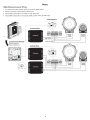
WIRING
T4652-S
Bi-Amp
Cossover
Wiring
I.
Use illustration for
proper
connection and be sure
to
maintain speaker polarity.
2.
Remove 4 screws from crossover bottom
to
detatch cover.
3.
When
BI-AMP
switched
OFF
for
one
amplifier,
use
only "TWT"
input.
4.
When
BI-AMP
switched
ON
for
two
dedicated
amplifier, use both
"TWT"
and
"WFR"
inputs.
\
Default
Setting
-----
....
/.··
81-AMP·
••
\
/OFF-,
rON
',
-
-
--
--
--------------------------------------------~-...1
IB
r)
Crossover
Cover
Removal
Remove
4
Screws
From
Bottom
to
Detatch
Cover
..
-
--
--
..
·...
..
..
....
..
...
\
~
~
..
T~l
\
. .
'.:TWT
-
+WFR
-
•TWT
,~
,'
·..
....
.
..
··"
·-
--
----
Standard
Mode
·----
.
..
.•.
:.:··/
WFR
Not
-
---
------~
-
i:-~~-~-~-~~~-
-
---
----------------
-
----
-
--·
•
•
•
•
•
•
•
""'kfilldlbsqoro
•
• •
• •
• •
•
•
5
..
----
....
/.··
81-AMP
·
·.
\
.:OFF-,
rON·.
~
..
j
~
r)
•
........... __
r
..
..
....
·
··
'
Woofer
(WFR)
Tweeter
(TWT)
Tweeter
(TWT)

Fran~ais
Lh_
MISE
EN
GARDE: avant d'entamer !'installation, deconnectez
Ia
broche negative
(-)
• de
Ia
batterie
pour
eviter
tout
risque
de
blessures, d'incendie ou
de
dommages a l'appareil.
PRATIQUEZ
UNE
ECOUTE
SANS
RISQUESMo
Une
exposition
continue
a
des
niveaux
de
pression
acoustique
supe
r
ieurs
a I
00
dB
pe
ut
causer
une
perte
d'acuite
aud
i
tive
perman
enc
e.
Les
systemes
audio
de
fo
r
te
puissance
pour
auto
peuvent
produire
des
niveaux
de
pression
acoustique
bien
au-dela
de
I 30 dB.
Faites
preuve
de
bon
sens
et
pratiquez
une
ecoute
sans
risques
Notes
pour
!'installation
Avant
de
commencer l'installation, suivez
les
reg!es ci-dessous :
I. Veillez a bien lire
et
comprendre
les instructions avant d'essayer d'installer les haut-par-
leurs.
2.
Par
mesure
de
securite,
debranchez
le
fil
negatif
de
Ia
batterie
avant
de
commencer
!'
in
-
stallation.
3.
Pour
faciliter
le
montage
des
haut-parleurs,
il
est
conseille d'installer
taus
les cables au
prealable.
4. Utilisez
des
connecteurs
de
haute
qualite
pour
assurer
une installation fiable
et
reduire
au
minimum
Ia
perte
de
signal
ou
de
puissance.
5. Reflechi
sse
z bien avant
de
percer.Veillez a
ne
pas Couper
ou
percer
le
reservoir
d'essence
, le diblage electrique
ou
les
conduites
de
carburant,
de freinage hydraulique ou
de
depression
en
travaillant
sur
un vehicul
e.
En
cas d'installation
sur
un bateau, veillez a ne
pas
couper
ou
percer
Ia
coque
principale.
6.
Ne
jamais faire
passer
de
fils
sous
le vehicule. Leur installation a l'interieur du vehicule ou
de
Ia
coque
assure
Ia
meilleure protection.
7. Evitez
de
faire
passer
des
fils
sur
des
bords
tranchants
ou
dans
des
orifices a
aretes
vives.
Utilisez
des
bagues
en
caoutchouc
ou
en
plastique
pour
proteger
les
fils
traversant
une
plaque
de
metal,
notamment
le tablier.
Montage
I. Determinez !'emplacement
des
haut-parleurs.Veillez
ace
que
Ia
surface plane
soit
assez
grande
pour
assurer un
contact
uniforme du haut-parleur.Verifiez
que
I'
emplacement
est
assez profond
pour
le
haut-parleur ;
en
cas
de
montage dans une portiere, actionnez
toutes
les commandes (fenetres, serrures, etc.) jusqu'aux extremites
de
leurs
courses
pour
vous
assurer
qu'il n'y a pas d'obstruction.
2.
Consultez
le
tableau des caracteristiques
pour
determiner
le diametre
de
I'
orifice a
decouper
pour
votre modele
de
haut-parleur.
Le
gabarit fourni
donne
aussi le bon diametre
de
decoupe.
3. Marquez
I'
emplacement des
vis
de
montage. Percez
le
s
trous
avec une m
ec
he
de
1/8
de
pouce (3,2 mm).
4. Faites passer
les
fils
de
haut-parleur a travers !'orifice
decoupe
et
branchez-les aux
barnes
du
haut-parleur.Veillez a bien
respecter
Ia
polarite Iars du branchement.
La
borne
positive
du
haut-parleur
est
indiquee
par
un « +
».
5. Sur les modeles a
trous
allonges,
mettez
le haut-parleur
en
place dans
Ia
decoup
e
et
installez
les
vis
dans les
trous
du
haut
et
du
bas.Vous
pourrez
alors faire
tourner
le
haut-parleur
pour
!'aligner
sur
les
autres
trous
de
montage. Une fois
cet
alignement effectue,
serrez
les
vis.
6. Serrez
les
vis
jusqu'a
ce
que
le haut-parleur soit
bien
ajuste,
de
t.u;:on
a prevenir tout
cli-
quetis, mais evitez
tout
sen-age excessif.
T4652-S & S composants
de
cablage
I. Utiliser !'illustration
pour
une
bonne connexion.
2. Assurez-vous
de
maintenir
orateur
polarite.
Axis
ON-OFF
I. Regie
sur
ON
ou
OFF match a
Ia
position relative
de
tweeter
a l'auditeur. Par defaut OFF satis-
fait
Ia
plupart des installations.
Switch
dB
I.
OdB
correspond a !'amplitude (pas d'augmentation I sans attenuation) des
le
tweeter
au meme
niveau que le milieu de gamme (woofer).
2.
+ 2dB augmen
te
-2dB
et
reduit !'amplitude
de
tweet
er en
rapport
a
Ia
moyenne gamme, (ideal
pour
adapter !'installation offset comme les
tweeters
situe en haut des panneaux
de
porte
et
Midranges faible en kick panneaux).
T4652-S Bi-Amp Cossover cablage
I. Utiliser !'illustration
pour
Ia
connexion
et
assurez-vous
de
maintenir
orateur
polarite.
2.
Suppression de 4
vis
de
liaison a bas detatch couverture.
3.
BI-AMP
Lorsque l'arret d'un amplificateur, utilisez uniquement '
1WT"
input.
4. Lorsque
BI
-
AMP
tension
pour
deux dedies amplificateur, utiliser les deux "TWT"
et
'WFR"
inputs.
6
Espanol
A\ PRECAUCION: Antes de
Ia
instalacion, desconecte
el
terminal negativo
de
Ia
bater
ia
~
(-)para
prevenir dafio a
Ia
unidad, incendio y/o posibles lesiones.
PRACTIQUE
EL
SONIDO
SEGURO
El
contacto
commuo
con
n1veles
de
pres16n
de
somdo
supenorcs
a I 00
dB
puede
causar
Ia
perd1da
permanente
de
Ia aud1c1on
Los
Sistemas
de
somdo
p
ara
autom6v1les
de
alta
potenCJa
pueden
producw
niveles
de
pres1on
de
somdo
supenores
a los
130
dB.
Use
su
sentido
comun
y
practique
el
sonido
seguro.
Consideraciones
para
I~
instalaci6n
Antes de comenzar cualquier
instalaci6n,
si
ga
estas
simples
normas:
I.
Asegurese
de
leer
cuidadosamente y
de
entender
las instrucciones antes
de
tratar
de
instalar
estos
altavoces.
2.
Por
seguridad, desconecte el
conductor
negativo
de
Ia
bateria antes
de
comenzar
Ia
insta-
lacion.
3.
Para facilitar el montaje, sugerimos que tienda todos los
cables
antes
de
montar
sus
altavoces
en
su
sitio.
4. Utilice conectores
de
alta calidad para
tener
una instalacion confiable y para reducir
al
mini-
ma
las perdidas
de
sefial o
de
potencia.
5.
;Piense siempre antes
de
perforar! Tenga cuidado
de
no
cortar
ni
perforar
en
tanques
de
combustible, tuberias
de
combustible, frenos o hidraulicas, tuberias
de
vacio o cableado elec-
trico
al
trabajar en un vehiculo.
Si
Ia
instalacion
se
hace en un
bote
, tenga cuidado
de
no
cor-
tar
ni
perforar a traves del
casco
principal.
6. Nunca tienda cables abajo del vehiculo. Tender los cables
adentro
del vehiculo o casco
pro-
porciona Ia mejor protecci6n.
7.
Evite
tender
cables arriba o a traves
de
bordes
filosos.
Use
arandelas aislantes
de
caucho
para proteger
los cables tendidos a traves
de
metal, especial mente
Ia
mampara cortafuegos.
Montaje
I. Determine adonde
se
montara
los altavoces.Asegurese
de
que
haya un
area
suficientemente
grande para
montar
de
manera plana el altavoz.Asegurese
de
que
ellugar
de
montaje sea
suficientemente profunda para
que
quepa el altavoz,
si
se
monta
en
una puerta, accione
todas
las
funciones (ventanas, cerradura, etc.)
en
toda
su
gama
de
funcionamiento para asegurarse
de
que
no haya obstrucciones.
2.
Consulte
Ia
tabla
de
especificaciones para determinar cuales son los diametros
correctos
para el agujero a
cortar
para su modelo
de
altavoz.
La
plantilla proporcionada tambien
le
da
Ia
medida
correcta
del
recorte
.
3. Marque
las
localidades para los tomillos
de
montaje. Perfore los ag
uj
e
ros
usa
ndo
una broca
de
1/8
pulg.
4. Tienda los cables del altavoz a traves del
recorte
y
conecte
a los terminales del altavoz.
Aseg(Jrese
de
usar
Ia
polaridad
correcta
al
conectar
los cables.
El
terminal positive del altavoz
esci
identificado
con
un
simbolo "+
...
5.
En
los modelos
con
agujeros ranurados, coloque el altavoz en el
recorte
e instale los tornil-
los
en
las ranuras
en
Ia
parte
superior e inferior. Esto le permitiril h
acer
girar el altavoz para
que
coincida con los agujeros
de
montaje restantes. Una vez alineados, apriete los tornillos.
6. Apriete los tornillos hasta
que
el altavoz
este
ajustado
en
su
sitio para evitar vibraciones.
No
apriete demasiado los tornillos.
T4652-S
Componente
de
cableado
I. Utilice
Ia
ilustraci6n para
una
correcta conexi6n.
2.
Aseg(J
rese
de
mantener
Ia
polaridad
de
los altavoces.
Eje
de
encendido
y
apagado
I.
En
ON
u OFF para que coincida
con
Ia
posicion
de
los
tweeter
en
re
lacion con el oyente.
Por
defecto posicion OFF cumple
Ia
mayoria
de
las
instalaciones.
dB
I. Coincide con
Ia
amplitud
OdB
(sin aumento o no
de
atenuaci6n),
de
el
tweeter
en el mismo
niv
el que los
de
gama media (woofer).
2.
+ 2B
de
aumento y -2dB reduce
Ia
amplitud
de
l
os
tweeter
en
relacion con Ia gama media, (ideal
cuando se pongan en venta compensar
Ia
instalacion
tweeters
de alta
como
situado
en
los pan-
eles
de
puerta y en el tiro bajo midranges paneles).
T4652 Bi-Amp Cossover
de
cableado
I.
Utilice
Ia
ilustraci6n para Ia correcta conexi6n y asegurese
de
mantener
Ia
pol
ar
idad
de
los
altavoces.
2.
Retire
lo
s 4 tornillos
de
Ia
parte
infe
ri
or
de
cruce detatch a cubrir.
3.
Cuando
BI-AMP
apagado
de
un
amplifi
ca
dor, utilice solo "TWT''
de
entrada.
4. Cuando
BI-AMP
encendido durante
dos
dedicados amplificador, use
tanto
''TWT" y "WFR"
insumos
.

Deutsch
.&.
VORSICHT:
Entfemen
Sie
vor
dem
Einbau
den
negative
Batteriepol,
um
Schiiden
am
Geriit, Feuer bzw.
mogliche
Verletzungen zu vermeiden.
PRAKTIZIEREN
SIE
SICHEREN
SOUND
Fortgesetzte
Ge
rauschdruckpegel
von
uber
I
00
dB
konnen beim Menschen zu
perm
ane
nt
em
Horv
erlust fuhren.
Leis
tungsstarke Autosoundsysteme konnen
Gerauschdruckpegel
erzeugen, die weit
uber
130
dB
liegen.
Bitte wenden
Sie
gesunden Menschenverstand
an
und praktizieren
Sie
sicheren Sound.
Einbauuberlegungen
Befolgen Sie
vor
dem
Einbau
diese
einfachen
Regeln:
I.
Lesen
Sie
die
Anleitung sorgf.iltig,
bevor
Sie
versuchen diese l.autsprecher einzubauen.
2. Entfemen
Sie
vor dem Einbau aus Sicherheitsgriinden das negative
Kabel
von
der
Batterie.
3.
Um
die Montage
zu erleichtem,
empfehlen
wir
aile Kabel
vor
der
Befestigung
lhrer
l.autsprecher zu
verlegen.
4. Vervvenden
Sie
nur
Qualitiitsstecker,
um einen
zuverlassigen
Einbau zu
gew3hrleisten
und
S
ignal-
und Stromverlust zu minimieren.
5. Denken Sie
nach, bevor
Sie
bohren! Achten
Sie
darauf, niche
in
den Benzintank, die Benzin-, Brems-
oder
hydraulischen
Leitungen,Vakuumleitungen
oder
Elektrokabel
zu schneiden
oder
zu bohren,
wenn Sie am Fahrzeug arbeiten.Achten
Sie
beim Einbau
in
einem Boot darauf, niche durch den
Bootsrumpf zu schneiden
oder
zu bohren.
6.
Verlegen
Sie
Kabel
nie
unter
dern Fahrzeug. Die
Kabel
im
Fahrzeug
oder
Bootsrumpf zu verlegen,
bietet
den
besten Schutz.
7. Vermeiden
Sie
es,
Kabel iiber scharle
Kanten zu verlegen.Verwenden
Sie
Gummi-
oder
Plastikrlnge,
um
Kabel
zu schiitzen,
die durch
Metall verlegt werden (besonders die Feuerwand).
Befestigung
I.
Entscheiden,
wo
die l.autsprecher befestigt
werden
sollen. Gewahrleisten,
dass
der
Pl
atz
ausre-
icht,
um
den
l.autsprecher
gleichmaBig
zu befestigen.
Gewahrleisten,
dass die Befestigungsstelle
ausreichende Tiefe
fur
den
l.autsprecher hat; beim Einbau in
einer
Tiire a
ile
Funktionen (Fenster,
Schloss
usw.)
in
ihrem ganzen Bereich ausprobieren
um
zu gewahrleisten,
dass keine
Blockierung
eintritt
2. Die
Tabelle
in
den Technischen
Daten
gibt
den
richtigen Lochdurchmesser
fur lhr
l.autsprechermodell
zum
Ausschneiden an. Die
beiliegende Schablone
zeigt
ebenfalls
die richtige
AusschneidegroBe an.
3. Die
Stellen fur
die Befestigungsschrauben markieren. Die
L
och
er
mit
einer
118-Zoll
(3,2 mm)
Bohrerspicze bohren.
4. Die l.autsprecherkabel durch das Loch fuhren und an
den l.autsprech
era
usgiingen
anschlieBen.
Beim
AnschlieBen
d
er
Kabel die ordnungsgemiiBe
Polaritiit
beachten.
Der
positive
Anschluss
des
l.autsprechers ist mit einem
,+"
markiert.
5.
Bei
Mod
ellen
mit
geschlitzten
Lochern den l.autsprecher
in
das Loch einpassen und die
Schrauben in
den
Schlitzen
oben
und unten befestigen. Dadurch konnen
Sie
den Lautsprecher
so
drehen
, dass die
iibrigen Befestigungslocher
passen. Nach
der
Ausrichtung die Schrauben
anziehen.
6. Die Schrauben anziehen, bis
der
l.autsprecher eng an seinem
Platz anliegt,
um
Klappem
zu ver-
hindem.
Die
Schrauben niche zu fest anziehen.
T 4652-S Komponente Verdrahtung
I.
Verwenden
Sie
fur
die richtige Verbindung
Illu
stration.
2.
Stellen Sie
sicher, dass die
Aufrechterhaltung
l.autsprecher
Polaritiit.
Axis ON-OFF-Schalter
I.
Auf
ON
oder
OFF.
um Position
der
HochtOner relativ
zum Horer. Standard-OFF-Position
entspricht den meisten
lnstallationen.
dB-Schalter
I.
Mit
der
Amplitude 0
dB (keine Zunahme
I
keine Diimpfung) v
on
der
Hoch
toner
auf
der
gle-
ichen Ebene wie die Mid-Range-(TT).
2. +2dbB -2dB
erh
oht und verringert die
Amplitude
der
Hochtoner
in
Bezug auf die
Mid
-Range-,
(ideal,
wenn
Offset-Installation
Hocht
o
ner
hoch wie in
Tiirverkleidungen
und
MitteltOner
gering
Kick
Pl
atten).
T4652-S Bi-Amp CossoverVerdrahtung
I.
V
erwe
nd
en
Sie
fur
di
e richtige Verbindung
Illustration
und v
ergew
iss
er
n
Sie
sich, um
l.autsprecher Polaritiit.
2. Ne
hm
en
Si
e 4
Schrauben von uncen nach
Crossover
detatch
deck
en.
3.
Bei
der
Bi-Amp ausgeschalt
et
fu
r einen
Verstiirker,
verw
e
nden
Sie
nur
''TWT"
In
put.
4.
Bei
der
Bi-Amp
eingeschaltet fur
zwei
spezie
ll
e Verstiirker, sowohl
"'TWr'
und
'W
F
R"
Eingiinge.
7
Italiano
A\
ATTENZIONE:
Prima
dell'installazione, scollegate
il
terminale
~
negativo (-)
della
bacteria
per
evitare danni
all'unici, pericoli
d'i
nce
ndio
e/o
potenziali lesioni
personali.
OSSERVATE LE
REGOLE
DEL
"SUONO
SENZA
PERICOLI"
La
costantc cspos1Z1ore
a
'
,e
ll d1
il
'
ess1onc
acust10 al d1 sopr
il
cl
e1
I
C>Jc
8
posso
no
ca
u
sa
l e
ld
pe1
dta
pc1
rnc.nente dell'ud1
to
I s1s:ern
aucl
1o
ad
a
ltc1
po'cr
' Zo
po
sso
no
p1 o
du1
re
l
1vcl
l' d1
pr
ess
1one
ac
us
l1
ca
ben
SL..pe
,·,orl dl I 30dB S1
co'"
'c
a
d
b.Jor
sen
so
e
l'os
se
1
Jdnza
delle
re~ole
eel
suo
no
se
n
za
per1co
l ·
Considerazioni
sull'installazione
Prima di iniziare
qualsiasi
operazione
d'installazione,
vi
consigliamo
di
seguire
queste
semplici
regole:
I.
Assicuratevi
di
aver letto
tutte
le istruzioni con cura e
di
averle capite prima
di
effettuare qualsiasi
tentativo d'installazione neiconfronti
de
ll'
uniti.
2. Per motivi
di
sicurezza,
scollegate
il
cavo negativo
dalla
batteria prima
di
dare
l'avvio
all'installazione.
3.
Per
facilicare
il
montaggio,
vi
suggeriamo
di
far sconrere
tutti
i
fili
prima di montare
Ia
vostra
unitii
nella
sua ubicazione.
4. Usate
connettori
di
alta
qualici.
per
garantire
un'installazione
che
di
affidamento e
per
ridunre
al
minimo
Ia
perdita
di
segnali
o
di
potenza.
5.
State
attenti prima
di
trapanare!
Cercate
di
non trapanare e
di
non incidere i serbatoi
della
benzina;
le
co
ndutture
del carburante, dei freni, del sistema
idraulico
e a depressione; nonche i
fili
elettrici
quando state
lavorando
su
qual
siasi
veicolo.
6.
Non
fate
mai
sconrere i
fili
sotto
il
veicolo.Avrete
Ia
protezione
migliore
faccendo sconrere i
fili
all'intemo del veicolo.
7.
Evicate
di
far
sconrere i
fili
sopra o attraverso
delle estremitii
affilate.
Usate guamizioni
di
tenuca
in
gomma o in
plastica
per
proteggere
qualsiasi
filo
che
passi attraverso
de
l metallo,
soprattutto
il
parafiamma.
Montaggio
I.
Decidete
dove
montare
gli
altoparlanti.Assicuratevi
che
sia un'area abbastanza grande
per
poter
montare
l'altoparlante
a
livello
e abbascanza profonda
per
poterfo
collocare
comodament
e.
Se
lo
montate
all'intemo
di
uno
sportello,
controllate
tutte
le funzioni (finestre,
serrature
, ecc.), una
alia volta,
per
assicurarvi
che
non
ci siano ostruzioni.
2.
Fate riferimento
alia tabella delle
specifiche
per
stabilire
il
diametro
conretto
del
foro
che
dovrete
praticare
per
il
modello del
vostro
altoparlante.
II
modello
fomito
anche
da
Ia
dimen-
sione adeguata
del ritaglio.
3.
Marcare
le
posizioni
per
le
viti
di
montaggio. Praticare i fori
con
una punta da trapano
di
liB
di
pollice
(3,2 mm).
4. Passare i
cavi
del
diffusore tramite
l'apertura
e
collegarli
ai
terminali.Verificare
che
Ia
polarici sia
corretta
quando
si
collegano
i cavi.
II
terminale
positivo
del
diffusore
e
identificato
dal "+".
5. Nei
modelli
con
fori a
slot, adattare
il
diffusore
nel
foro
ricagliato
e inserire
le
viti
negli
slot
in
alto
e
in
basso. Cosl facendo
si
potr.\
ruotare
il
diffusore
per
allinearlo
con
i rimanenti
for
i di
montaggio.
Serrare
le
viti
quando
si
e
ottenuto
l'allineamento.
6.
Per
evitare
rumore
dovuto
a vibrazioni
serrare
le
viti finche
il
diffu
sore
non
sia
sa
ldamente
in
posizione.
Non
serrare
le
viti in
modo
eccessivo.
T4652-S Componente Cablaggio
I
. U
sa
illustrazi
one
per
Ia
conretta connessione.
2.
Ricordati di ma
ntenere
Ia
polarici
dei diffusori.
AsseON-OFF
I. lmpostato su
ON
o
OFF
per
corrispondenza di posizione rispetto
al
cweeter
ascoltatore.
Default OFF
posizione
so
ddis
fa
Ia
maggior
parte
degli
impianti.
dB
I.
OdB
corr
i
spo
nde
l'ampiezza
(nessun aume
nto
I
no
atte
nuazione) di
il
tweeter
e
allo
stesso
livel-
lo,
co
me
il
m
id
-range (woofer).
2. + 2dB aumenta -2dB e riduce
l'ampiezza del
tweeter
nella
rispetto
al
mid-range,
(ideale
quando
corrispondenti
compensare
l'installazione
come
tweeter
situato
in
alto
pannelli
porta
e
midrange a basso
contenuto
di
calcio pannelli).
T4652-S Bi-Amp
Wiring
Cossover
I.
Usa
illustrazione
per
Ia
corretta
conness
io
ne
ed
esse
re
centi
di
mantenere
Ia
polariti
d
ei
diffu-
sori.
2.
4
Rimuovere
le
viti
dal fondo di crosso
ver
deta
tch
cope
ntina.
3.
Quando
BI
-AMP
s
pento
p
er
un
amplificatore, utilizzare
so
lo
"'TVVT''
in
put.
4.
Quando
BI-AMP
attivata
per
due
amplificatore
dedicate,
l'uso sia
'
'TWT
"
e
'WFR"
ingressi.

T4652-S
Component
System
1.00"
(25mm)
Verify Scale
Before Using
Template
Mounting
Template
T4652
Midrange
Mounting
Holes
6.18"
(157mm)
_
__,
+
T
4652
Midrange
Hole
Cutout
5.67"
(144mm)
/
I
I
I
I
,
....
I
\
'
/
'
/
Tweeter
'
'
\
'
+-
\
\
.,,
I
1.75"
(44mm)
/
'
/
'
-----

LIMITED
WARRANTY
STATEMENT
Rockford Corporation offers a
limited warranty
on
Rockford Fosgate products
on
the
following terms:
Length
of
Warranty
Speakers-
I Year. Any Factory Refurbished
Product-
90
days
(receipt
required)
What
is Covered
This warranty
applies only
to
Rockford Fosgate products sold
to
consumers
by
Authorized Rockford Fosgate
Dealers
in
the
United
States
of
America
or
its possessions. Product purchased
by
consumers from an
Authorized Rockford Fosgate Dealer
in
another
country
are
covered only
by
that
country's Distributor and
not
by
Rockford Corporation.
Who
is
Covered
This warranty covers only
the
original purchaser
of
Rockford product purchased from an Authorized
Rockford Fosgate Dealer
in
the
United States.
In
order
to
receive service,
the
purchaser must provide
Rockford with a copy
of
the
receipt stating
the
customer
name, dealer name, product purchased and date
of
purchase. Products found
to
be defective during
the
warranty period
will
be repaired
or
replaced
(with a product deemed
to
be equivalent)
at
Rockford's discretion.
What
is
Not
Covered
I.
Damage caused
by
accident, abuse, improper operations, water, theft, shipping
2.
Any
cost
or
expense related
to
the
removal
or
reinstallation
of
product
3.
Service performed
by
anyone
other
than Rockford
or
an Authorized Rockford Fosgate Service
Center
4.
Any product which has had
the
serial number defaced, altered,
or
removed
5.
Subsequent damage
to
other
components
6.
Any product purchased outside
the
U.S.
7.
Any product
not
purchased from an Authorized Rockford Fosgate Dealer
Limit
on
Implied
Warranties
Any
implied
warranties
including
warranties of fitness for use and merchantability are limited
in
duration
to
the
period of the express warranty set forth above. Some states
do
not
allow limitations on the length
of
an
implied
warranty, so this limitation
may
not
apply.
No
person
is
authorized
to
assume for Rockford Fosgate
any
other
liability
in
connection
with
the sale
of
the product.
How
to
Obtain
Service
Contact
the
Authorized Rockford Fosgate Dealer you purchased this product from.
If
you need further
assistance,
call
1-800-669-9899
for Rockford
Customer
Service.You must obtain an
RA#
(Return
Authorization
number)
to
return any product
to
Rockford Fosgate.You are responsible for shipment
of product
to
Rockford.
E.U
Warranty
This product meets
the
current
EU
warranty requirements, see your Authorized dealer for details.
Rockford
Fosgate
Rockford
Corporation
600 South
Rockford Drive
Tempe, Arizona 85281 U.S.A._
In
U.S.A.,
(480) 967-3565 -
Customer
Service 1-800-669-9899
www.rockfordfosgate.com
Designed
and
Engineered
by Rockford
Fosgate,
Tempe,
AZ.
USA.
©
20
13
Rockford
Corporation.
All
Rights Reserved.
ROCKFORD FOSGATE
and associated logos
where
applicable
are
registered
trademarks
of
Rockford
Corporation
in
the
United States
and/or
other
countries.
All
other
trademarks
are
the
property
of
their
respective
owners.
Specifications subject
to
change
without
notice.
1230-58449-0 I Printed
in
China
-
 1
1
-
 2
2
-
 3
3
-
 4
4
-
 5
5
-
 6
6
-
 7
7
-
 8
8
-
 9
9


Rockford Fosgate T4652-S Installation & Operation Manual
- Categoria
- Altoparlanti per auto
- Tipo
- Installation & Operation Manual
in altre lingue
- English: Rockford Fosgate T4652-S
- français: Rockford Fosgate T4652-S
- español: Rockford Fosgate T4652-S
- Deutsch: Rockford Fosgate T4652-S
Documenti correlati
-
 Rockford Fosgate T3652-S Installation & Operation Manual
-
Rockford Fosgate power T252-S Installation & Operation Manual
-
Rockford Fosgate 3-Way FNQ3146 Manuale utente
-
Rockford Fosgate T1 T-S Installation & Operation Manual
-
 Rockford Fosgate PUNCH PM2T-S Installation & Operation Manual
-
Rockford Fosgate T165-S Installation & Operation Manual
-
 Rockford Fosgate Punch PP8-T Installation & Operation Manual
-
Rockford Fosgate Punch P152-S Installation & Operation Manual
-
-
Rockford Fosgate M282-Wake Installation & Operation